

CALEFFI SATK32105, SATK32103, SATK32 Series Instructions For Installation, Commissioning And Maintenance
Page 1
H0003193
ww.caleffi.com
w
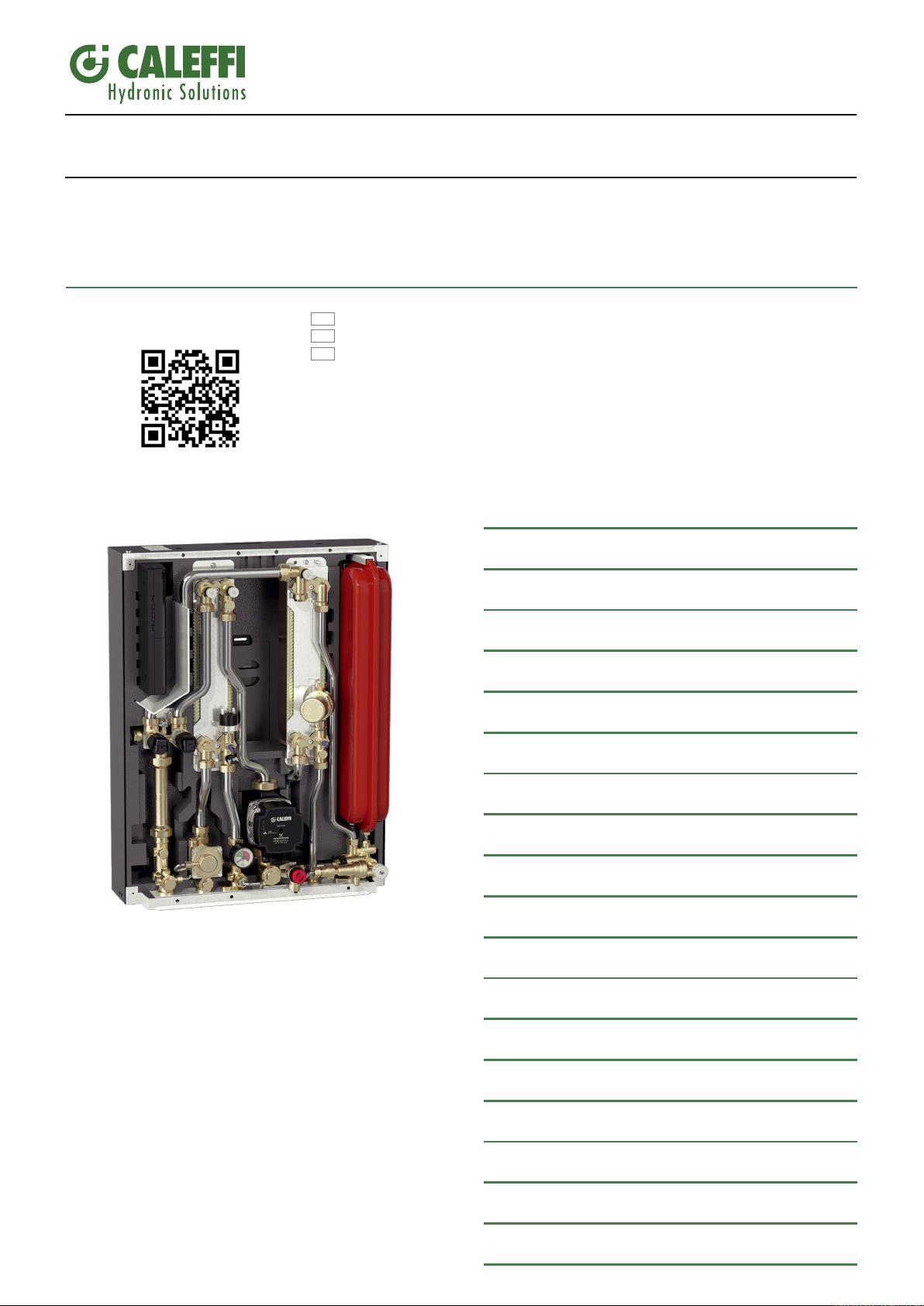
SATK series wall-mounted indirect Heat Interface Unit
SATK32 series
INSTRUCTIONS FOR INSTALLATION, COMMISSIONING AND MAINTENANCE
All languages are available on:
FR
NL
I
Function
The SATK series HIU allows independent control of heat regulation and
domestic hot water production within centralised heating systems or systems
served by district heating networks.
The heat interface unit features exceptional flexibility of installation and remote
controllable smart electronic functions designed to enhance efficiency of the
system.
CONTENTS
Safety instructions
Dimensions - Technical specifications
Hydraulic components and diagram
Hydraulic installation
Electrical installation
Commissioning
Remote user interface quick guide
2
3
4
5
8
9
10
Product range
SATK32103 Indirect wall-mounted HIU for instantaneous
SATK32105 Indirect wall-mounted HIU for instantaneous
(1)
Primary side head > 50 kPa, primary flow temperature 70°C,
DHW 10 - 50°C
domestic hot water production, capacity 50 kW
domestic hot water production, capacity 60 kW
Heating function
DHW function - Comfort functions
Anti-legionella function
Primary flow rate limitation
Circulator - curves and setting
Auxiliary microswitch
(1)
.
(1)
.
Modbus
Safety and alarms
Electronic circuit board
Periodic maintenance
Troubleshooting
12
13
14
14
15
16
17
18
19
20
22
Commissioning check-list
24
Page 2
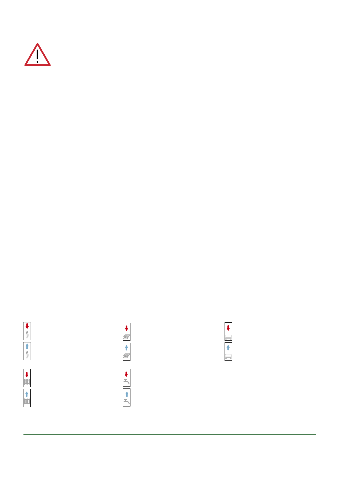
SAFETY INSTRUCTIONS
Primary circuit flow
Primary circuit return
Low temperature circuit flow
Low temperature circuit return
Medium temperature circuit flow
Medium temperature circuit return
Domestic hot water outlet
Domestic cold water inlet
High temperature circuit flow
High temperature circuit return
WARNINGS
These instructions must be read and understood before installing and servicing the device.
IMPORTANT! FAILURE TO FOLLOW THESE INSTRUCTIONS COULD RESULT IN A SAFETY HAZARD!
1 The device must be installed, commissioned and serviced by qualified technical personnel in accordance with national regulations and/or relevant local
requirements.
2 If the device is not installed, commissioned and serviced correctly in accordance with the instructions provided in this manual, it may not work properly and may
endanger the user.
3 Clean the pipes of any particles, rust, incrustations, limescale, welding slag and any other contaminants. The hydraulic circuit must be clean.
4 Make sure that all connection fittings are watertight.
5 When connecting water pipes, take care not to subject the threads to excessive mechanical stress. Over time this could result in breakage, with water leaks causing
damage and/or injury.
6 Water temperatures higher than 50°C may cause severe burns. When installing, commissioning and servicing the device, take the necessary precautions so that
these temperatures will not be hazardous for people.
7 In the case of particularly hard or impure water, the device must be fitted for filtering and
legislation. Otherwise the device may be damaged and will not work properly.
8 Any use of the device other than its intended use is prohibited.
9 Any combination of the device with other system components must be made while taking the operational characteristics of both units into consideration.
10 An combination coupling could compromise the operation of the device and/or system.
IMPORTANT: Risk of electric shock. Live parts. Shut off the electric supply before opening the device enclosure.
1 During installation and maintenance operations, always avoid direct contact with live or potentially hazardous parts.
2 The device must not be exposed to dripping water or humidity, direct sunlight, the weather, heat sources or high intensity electromagnetic fields. This device cannot
be used in areas at risk of explosion or fire.
3 The device must be connected to an independent two-pole switch. If work must
with automatic or time reset, or which may be reset accidentally.
4 Use suitable automatic protection devices in accordance with the electrical characteristics of the region in which the device is installed and in compliance with
current legislation.
5 The device must always be earthed before it is connected to the electric supply. If the device must be removed, always disconnect the earth connection after
disconnecting the electric supply conductors. Check that the earth connection has been made to the highest of standards under applicable legislation.
6 Electrical installation must only be carried out by a qualified technician, in accordance with legal requirements.
7 The appliance does not contain asbestos or mercury.
8 The device is not designed for use by persons of reduced mental, physical or sensory capacity (including children) or persons lacking experience, unless they are
supervised or instructed in use of the device by a person responsible for their personal safety.
treating the water before it enters the device,
be carried out on the device, cut off
in accordance with current
the electric supply first. Do not use devices
NOTES:
1 Install water hammer arresters to compensate for any overpressure in the domestic water circuit;
2 In the presence of hot water recirculation or if a check valve is fitted into the domestic cold water inlet, suitable devices must be used to accommodate the
expansion of the medium contained within the system and the heat interface unit;
3 All hydraulic connections must be visually checked while pressurising the system. Vibration during transport may cause the connections to become loose. If a fitting
needs to be tightened apply a proper tightening torque, otherwise the components may be damaged by overtightening.
For the updated version of the technical documentation refer to www.caleffi.it.
Key to symbols
LEAVE THIS MANUAL AS A REFERENCE GUIDE FOR THE USER. DISPOSE OF THE PRODUCT IN COMPLIANCE WITH CURRENT LEGISLATION
THE MANUFACTURER RESERVES THE RIGHT TO CEASE PRODUCTION AT ANY TIME AND TO MAKE ANY CHANGES DEEMED USEFUL OR NECESSARY
WITHOUT THE OBLIGATION OF PRIOR NOTICE.
2
Page 3
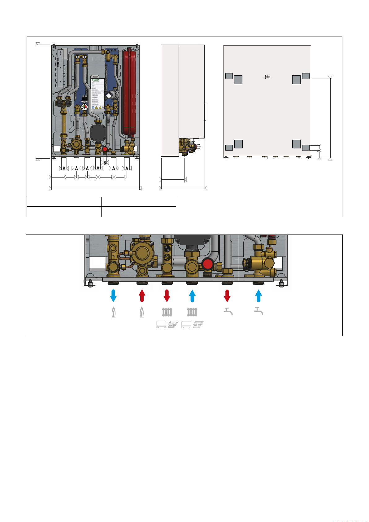
130
245
70 70 60 60 85 75
490
630
42 28
444
Dimensions
A B
3/4” 1/2”
Description of connections
SATK32 technical specifications
Medium: water
Max. percentage of glycol: 30%
Maximum medium temperature: 90°C
Max. working pressure: - primary circuit: 1,6 MPa (16 bar)
- secondary circuit: 0,3 MPa (3 bar)
- domestic circuit: 1 MPa (10 bar)
Primary circuit nominal flow rate: 1,2 m
Nominal pressure loss on primary circuit: Dp 50 kPa (0,5 bar)
Maximum pressure on primary circuit: Dp 600 kPa (6 bar)
Domestic water circuit max. flow rate: 24 l/min (0,4 l/s)
Minimum flow rate to activate domestic water flow meter: 2 l/min ±0,3
Electric supply: 230 V (ac) ±10% 50Hz
Max power consumption: 80 W
Protection class: IP 40
Pump: UPM3 15-70
Actuators: 24 V stepper motor
Probes: NTC 10 kΩ
Safety relief valve setting: 0,3 MPa (3 bar)
Safety thermostat: 55°C ±3
Expansion vessel: - capacity: 7 l
Pressure switch: - opening: 40 kPa (0,4 bar)
- pre-charge value: 0,1 MPa (1 bar)
- closing: 80 kPa (0,8 bar)
Materials
Components: brass UNI EN12165 CW617N
Connecting pipes: steel
Frame: RAL 9010 painted steel
Exchanger: stainless steel brazed with copper
3
/h
Insulation
Material: EPP
Density: 45 kg/m
3
Working temperature range: 3-90°C
Thermal conductivity: 0,04 W/mK
3
Page 4
3
9
4
7
10
8
5
2
1
20
11
14
19
1
8
17
13
1
2
22
2
3
24
16
27
25
26
21
6
15
29
28
T
S
P
TA
2
V
V
V
V
V
V
3 4
5
6
7
8
9
10
11
12
13
14
15
18
17
16
20
19
23
24
25
26
27
28
29
21
22
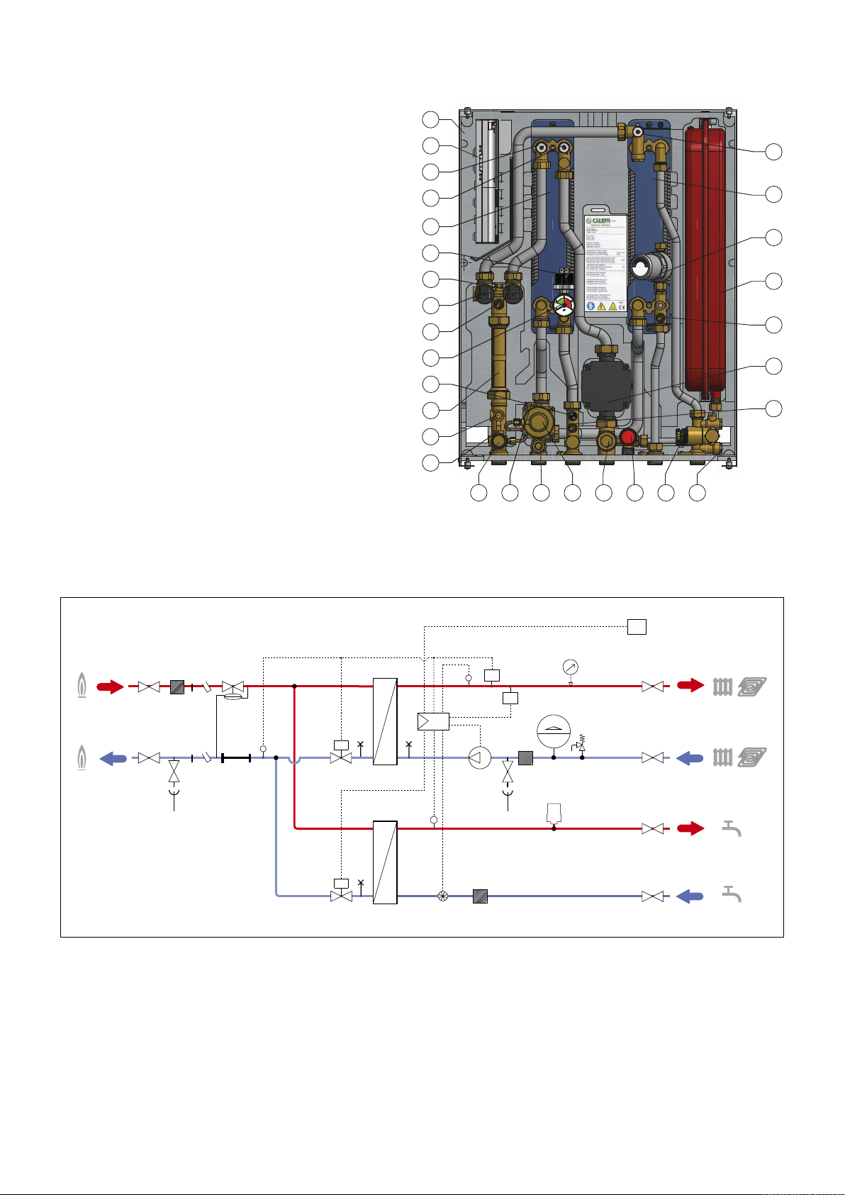
Characteristic components
1. Frame
2. Controller
3. Heating exchanger primary circuit air venting/drain
4. Heating exchanger secondary circuit air venting/drain
5. Heating exchanger
6. Pressure switch
7. 2-way modulating valve - Heating
8. 2-way modulating valve - DHW
9. Return temperature probe
10. Pressure gauge
11. Safety thermostat
12. 130 mm heat meter template
13. 1/4” F pressure test port
14. Connection for M10x1 heat meter return probe
15. Primary drain cock
16. Connection for M10x1 heat meter flow probe
17. Mesh strainer + 1/4” F pressure test port
18. Differential pressure regulating valve
19. Secondary drain cock + mesh strainer
20. Safety relief valve
21. Flow meter (turbine + sensor)
22. Mesh strainer
23. Heating flow temperature probe
24. Pump
25. DHW temperature probe
26. Expansion vessel
27. Water hammer arrester
28. DHW exchanger
29. DHW exchanger primary circuit air venting/drain
Hydraulic diagram
4
Page 5
Hydraulic installation
Notes for the installer
The SATK series HIU is designed for installation in a sheltered domestic environment (or similar), therefore it cannot be installed or used outdoors,
i.e. in areas directly exposed to the weather. Outdoor installation may cause malfunctioning and hazards.
If the appliance is enclosed inside or between cabinets, sufficient space must be provided for routine maintenance procedures. It is recommended
NOT to place electrical devices underneath the HIU, as they may be damaged in the event of safety relief valve activation if not connected to a
discharge tundish, or in the event of leaks occurring at the hydraulic fittings. If this advice is not heeded, the manufacturer cannot be held responsible
for any resulting damage.
In the event of a malfunction, fault or incorrect operation, the appliance should be deactivated; contact a qualified technician for assistance.
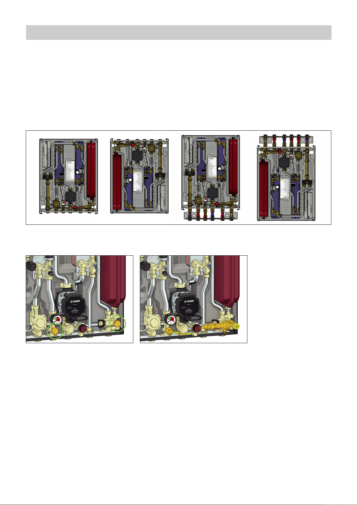
Hydraulic connections - reversibility
Installation of the SATK32 series heat interface unit is reversible (top-down). Installation in the two positions is possible with or without template code
789023.
Charging unit
To install the charging unit with backflow preventer code 572120, proceed as follows:
- remove the nuts shown in the figure with letter “A”;
A
A
- Insert the charging unit as shown in the figure, using the supplied seals.
Preliminary operations - installation without template
After having established the point of installation of the appliance, perform the following operations:
· Mark the holes required for the bracket to secure the HIU to the wall
· Mark the position of the hydraulic connections
Check the measurements again and, based on the above connection diagram and the dimensions shown on page 3, proceed with the installation
of the following lines:
• Hydraulic:
1. connection to the central system line
2. heating circuit connection
3. domestic water circuit connection
4. conveyance of safety relief valve and charging unit backflow preventer discharge
NOTE:
We recommend installing manual shut-off valves, especially on the connections to the primary line, thus allowing any necessary maintenance work
to be carried out without having to empty the centralised system.
Before installation, it is recommended to carry out accurate flushing of all the pipes of the system in order to remove any residue or impurities that
could endanger correct operation of the HIU.
In order to facilitate these operations a manual bypass flushing valve is available (code 789110).
5
Page 6
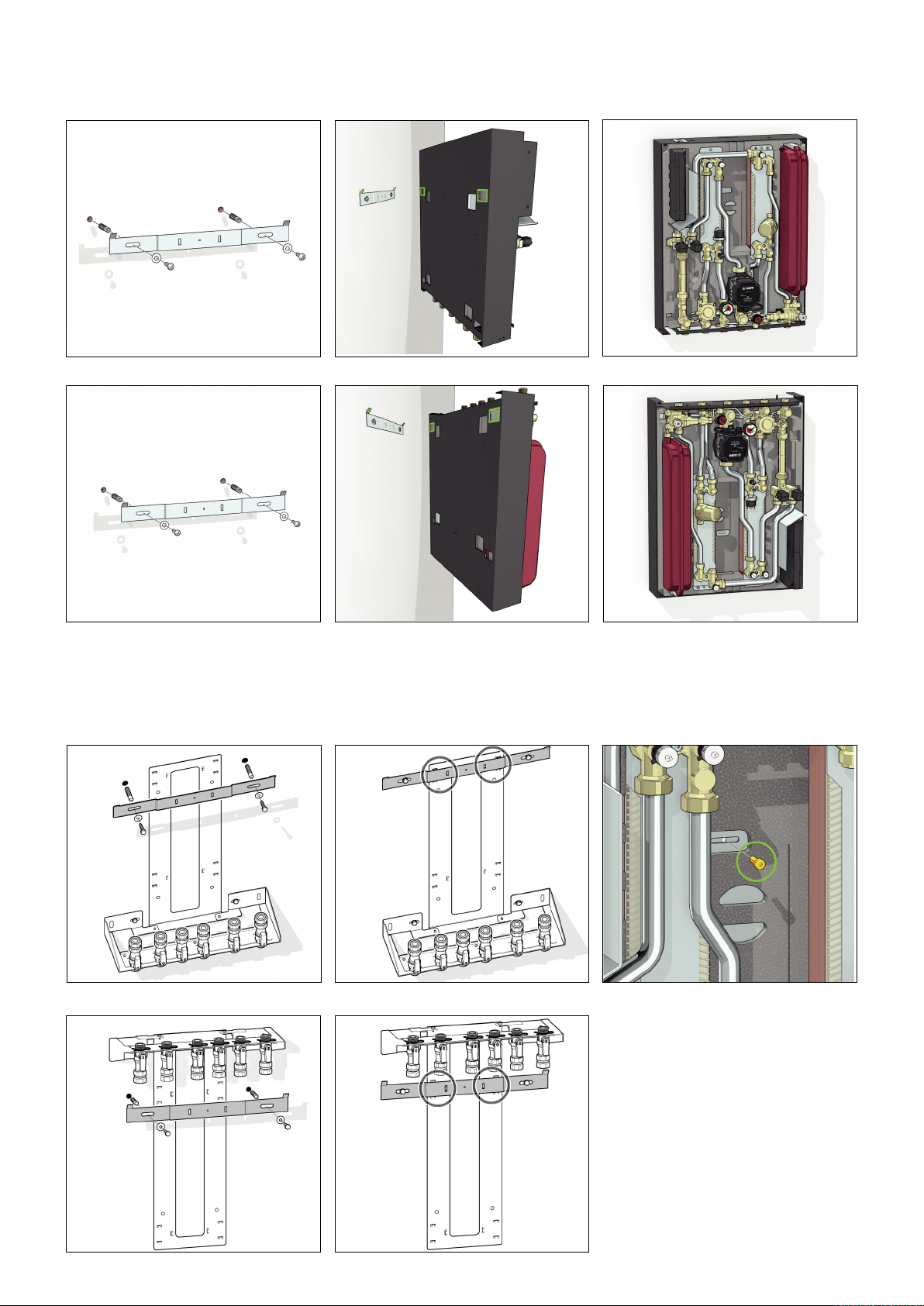
Installation procedure (without template)
Secure the metal bracket supplied with the HIU to the wall using suitable wall anchors.
Connections on the bottom
123
Connections on the top
123
Installation with template
NOTE:
Before installation, it is recommended to carry out accurate flushing of all the pipes of the system in order to remove any residue or impurities that
could endanger correct operation of the HIU.
In order to facilitate these operations a manual bypass flushing valve is available (code 789110).
Connections on the bottom
123
Connections on the top
12
N.B.:
In the case of installation with connections
on the bottom fit the safety screw (figure
3).
Install SATK32 as per the above pictures and
close the 6 nuts using the fiber gaskets
supplied.
6
Page 7
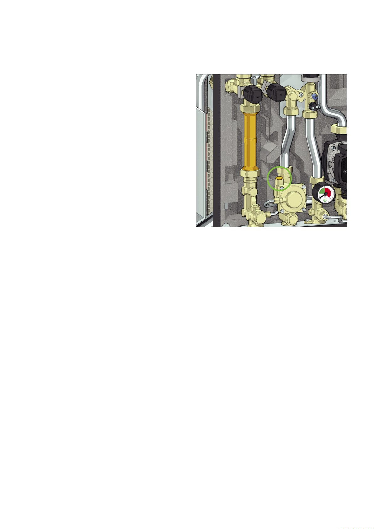
Conveyance of the safety relief valve
The safety relief valve is equipped with a compression fitting suitable for 15 mm copper pipe and can be rotated in accordance with the HIU installation
position. If SATK32 is installed with upward facing connections, use discharge pipe code 789832, specifically designed to route the valve drain line
through the insulation shell, without damaging the internal electronic components.
Heat meter installation
The HIU is fitted to house a compact heat meter (with incorporated
return probe) with 1” threaded connections and length of 130 mm.
Before carrying out any maintenance, repair or part replacement work,
proceed as follows:
- cut off the electric supply
- remove the cover
- close the shut-off valves on the primary flow and return
- empty the HIU using the drain cocks provided
- remove the template (A)
- remove the cap (B)
- install the flow meter on the return pipe. To tighten the nuts apply
maximum tightening torque of 25 Nm, taking account of the
indications of the heat meter manufacturer.
- install the flow probe in the M10 pocket (B).
Please refer to the heat meter technical data sheets for further
information.
A
B
7
Page 8
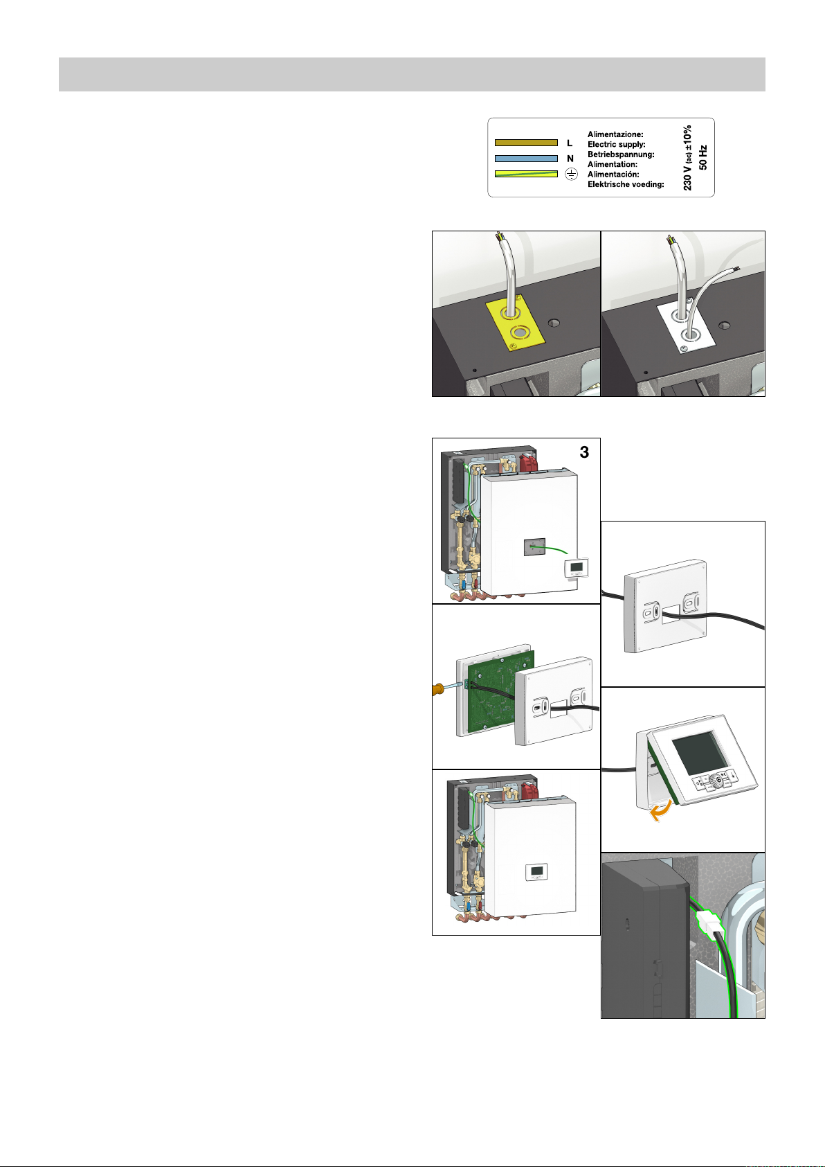
Electrical installation
Connection to the electric supply
The appliance is supplied with an electric supply cable which is not
fitted with a plug.
The appliance should be electrically connected to a 230 V (ac) singlephase + earth mains supply using the three-wire cable marked with
the label as specified aside, observing the LIVE (L) - NEUTRAL (N)
polarities and the earth connection. This line must be connected to a
circuit breaker device.
To extend the cable if necessary, use a flexible cable suitable for
kitchen and heating appliances and for home, kitchen and office
installations, also in humid environments subject to medium levels of
mechanical stress (e.g. H05V2V2-F: Uo/U 300/500 V). Cable
minimum cross-section 3 x 0,75 mm
Make sure that the electrical system can withstand the maximum
power consumption of the appliance, with particular emphasis on the
cross-section of the wires.
If you have any doubts, contact a qualified technician to request a
thorough check of the electrical system.
Electrical safety of the appliance is only achieved when it is correctly
connected to an effective earthing system, constructed as specified in
current safety regulations. This is a compulsory safety requirement.
Observe the applicable regulations in force in the country of
installation.
Use the cable pathway provided, as shown in figure 1.
Optional electric connections
The controller has a door on the front providing access to terminal
boards for optional wiring (see chapter “circuit board details”). The
connections in question are all low voltage or potential-free. Any wiring
must be directed toward the exterior of the HIU, using the pathways
provided in the insulation and on the frame. All the low voltage lines
must be routed through a single dedicated cable raceway, using the
pathway that is not used for the electric supply cable (see figure 2), so
that they are separate from the 230 V electric cables.
Any other high voltage connection, e.g. the one from the auxilliary
microswitch (see pages 13 and 16) must pass through the same cable
pathway used for the main electric supply.
Remote user interface connection
The HIU user interface has the dual function of control device and
room thermostat. The remote user interface can be installed on board
the HIU or in the room in a position where the temperature
measurements will be of significance for control of the heating function
(in a heated room in a position where the temperature read by the
thermostat is not affected by any nearby heat sources).
2
.
12
3
4
5
6
Installation on board the HIU
If the remote user interface is fitted in the dedicated location on the
cover of the HIU, the thermostat function must be disabled (in this
case an external thermostat must be used, as described in the next
section). The adjacent figures show how to install the remote control
unit:
- Feed the cable from the regulator through the hole in the cover (3);
- Feed the cable from the regulator through the rear of the interface
(4);
- Connect the two wires to the terminals on the electronic circuit
board (the cable is not polarised) (5);
- Close the interface and position it in its housing on the cover (6), (7);
- If necessary, secure the interface from inside the cover by means of
the supplied pair of self tapping screws, spacers, and washers;
- Plug in the connector (8).
The thermostat function is enabled by default (refer to the
remote control user manual for disabling it).
7
8
8
Page 9

E
XP PORT OTSRT
PREPAID
AUX
RS-485 BUS
Installation in the room
Use the cable outlet provided for connection of the remote user
interface to the electronic circuit board.
The chrono-thermostat function has to be enabled through the remote
control. Refer to the dedicated user manual for the procedure.
Use of an external room thermostat
An external room thermostat, if installed, must necessarily be with
potential-free contact.
The external thermostat has to be connected to the terminals “RT”
shown in the adjacent figure. The terminals can be accessed by
removing the door on the HIU electronic regulator (see page 19).
In case the thermostat function of the remote user interface is
enabled, any external thermostat will work in parallel (management of
different temperature zones).
Alternatively, when the thermostat function of the remote user
interface is disabled, the interface can be used to define the hourly
programming of the space heating function for all thermostats
connected to the terminals “RT”.
Refer to the user interface dedicated manual.
Commissioning
Filling the central heating system
Open the shut-off valves on the connections to the centralised line
and, in the central heating system, proceed with charging the system
to the design pressure.
Once these procedures are complete, vent the system and check its
pressure again (repeat the filling process if necessary)
N.B. during the procedures for venting/draining the system use
suitable measures to avoid the risk of any liquid dripping onto the
electronic components.
Vessel pre-charge check
Perform the following steps:
- Use a pressure gauge to check the pre-charge value
- If necessary, restore the pre-charge value shown in the technical
specifications.
Filling the user system
SATK32 series HIU can be fitted with a charging unit equipped with a
backflow preventer (F), check valve (E) and cock (G) (code 572120).
When filling the system for the first time or for subsequent top-up
procedures following a heating circuit pressure switch fault, restore the
system pressure (0,12–0,2 MPa - 1,2–2 bar) by opening cock (G) and
checking the value by means of the pressure gauge (D).
Once the correct pressure has been reached, close the cock (G), vent
the system and re-check the pressure (repeat the filling process if
necessary).
System start-up
Before starting the HIU, visually check the hydraulic connections for
the absence of any leakage and all the electric connections. After
finishing the check, activate the electric supply to the HIU and check
for the presence of any error signal.
If there is any, eliminate the fault indicated (see page 18) and proceed
with setting the set point of the domestic water and heating cycles,
programming the remote user interface according to the desired
temperatures and times, and checking the operating cycles.
Fitting the cover
Fit the cover on the HIU by inserting the pins (A) in the locations
provided (B).
Secure the cover by tightening the 4 screws provided (C).
C
B
A
D
G
E
9
F
Page 10

Remote user interface quick guide
(mode)
DHW ON/OFF
Heating ON/OFF
(set)
C
urrent time/date
Set point temperature
k outside temperature compensation
(day/night)
Daytime/night-time setting
(temp)
Tem pe ra tu re
display
(ambient set point
+
probes)
(prog)
Heating hourly
programming and
“comfort” function
(reset)
Resettable error reset/floor slab
heating function
(R)
+/-
DISPLAY: BUTTONS:
The digits in the center of the display show the current ambient temperature, if the thermostat function is enabled.
In case the latter is disabled, the digits show DHW temperature and heating flow temperature when the HIU is in operation, “--.-” when in stand-by.
Selecting the active services (DHW/heating)
Press the <mode> key repeatedly to scroll
through the various available operating
modes.
Heating + DHW (“winter” mode) Heating only
OFF DHW only (“summer” mode)
Selecting set points, current time and
comfort function
Press the <set> key repeatedly to set the
current time, set point temperatures and
comfort function. The value can be modified
by turning knob <R>.
Night-time ambient temperature (*) Heating flow temperature DHW temperature
10
Current hours, minutes and day Daytime ambient temperature (*)
Page 11

Primary limit/set return temperature in
heating mode (**)
Primary limit/set return temperature in
DHW mode (**)
Comfort function (ON/OFF or according
to weekly program) (see page 13)
(*) if the thermostat function of the remote user interface is enabled.
(**) if these set points cannot be changed you must set parameter t07 to value 0 in the technical menu (see “access to technical menu” below).
Parameter t07= 1 “freezes” the operating set points to prevent inadvertent modifications by the user.
Temperature display
Press the <temp> key repeatedly to display
the current ambient temperature set point
and the temperature values read by the
three probes of the HIU.
Heating flow probe temperature Primary return probe temperature
(*) if the thermostat function of the remote user interface is enabled.
Access to technical menu
Press the <mode> key repeatedly to set the
HIU to OFF status.
Current ambient temperature set
point (*)
Heat interface unit in OFF mode
DHW probe temperature
Hold the <set>, <day/night> and <temp>
keys pressed together for 10 seconds.
Access to the technical parameters
To exit the menu, wait a few seconds or press the <reset> key. Re-enable the required services using the <mode> key.
Refer to the remote control user manual for the hourly programming of space heating and DHW comfort function.
Once “TSP” appears on the display, confirm
access by pressing the central knob <R>.
By rotating knob <R> it is possible to scroll
through the various parameters, which can
then be edited, pressing and rotating knob
<R>.
Technical parameter t00
11
Page 12

Text (°C)
T flow (°C)
MIN
5
0-5
-15
MAX
10
-10
20
15
25
30
-20
k =
3.0
k
=
2.5
k
=
2
.0
k
=
1
.5
k
=
1.0
k
=
0.5
k =
0.0
HIU setting at HIGH/LOW temperature
The HIU is set at LOW temperature by default (underfloor heating,
parameter t00 = 1). To change this setting and supply a system with
high temperature terminals go to the technical menu (see page 11)
and set parameter t00 to 0.
DEFAULT SETTING: set point regulation
(technical parameter t01 = 0)
When heating cycle activation is requested by the room thermostat,
the circulation pump is powered while the modulating valve is opened
gradually until the set point temperature is reached.
The circulation pump is stopped and the modulating valve is closed at
the end of the heating cycle. The heating cycle ON condition is indicated
by the blinking symbol.
OPTIONAL SETTING: primary return temperature limit
(technical parameter t01 = 1)
When heating cycle activation is requested by the room thermostat,
the circulation pump is powered while the modulating valve is opened
gradually until the set point temperature is reached, if the return
temperature is lower than or equal to the set limit value. In case this
condition is not met, the flow temperature is reduced (by a maximum
of 15°C for HIU in HIGH temperature, and maximum 3°C if in LOW
temperature), in order to bring return temperature within the limit
values. When the flow temperature must be reduced in order to limit
return, the icon appears on the display.
Heating flow/ primary return limit temperature setting
To set the flow temperature press the <SET> key until the symbol in
the red circle appears; for the return temperature limit press the key
until the symbols in the green circle are displayed. Use the <R> knob
to change the value (*).
The flow temperature range is:
25–45°C for heat interface units in LOW temperature
45–75°C for heat interface units in HIGH temperature
The primary return limit temperature range is:
15–42°C for heat interface units in LOW temperature
30–70°C for heat interface units in HIGH temperature
OPTIONAL SETTING: modulating temperature regulation with
compensated set point (technical parameter t01= 2)
When the function is enabled, the flow temperature is modified
(± 10°C with respect to the set point for HIU in HIGH temperature,
± 3°C if in LOW temperature) according to the temperature detected
by the return probe in order to maintain this latter temperature value
constant. This keeps the actual thermal output of the slab under
control, and consequently also the ambient thermal load. The thermal
response time of the system is thus minimised.
This feature should not be used in combination with thermostatic
radiator valves.
When the function is enabled the display shows the symbol .
OPTIONAL SETTING: weather compensation (technical
parameter t01 = 3)
When the function is enabled, the flow temperature is calculated
based on the temperature detected by the outside probe (optional), in
accordance with the curve shown below. The “k” coefficient can be
changed by pressing <SET> button until the related setting appears.
Heating function
The display shows the symbol .
MAX is the set temperature value
MIN is 45°C for HIGH temp. HIUs, 25°C for LOW temp. ones.
(*) if these set points cannot be changed you must set parameter t07
to value 0 in the technical menu (see “access to technical menu”
below). Parameter t07 = 1 “freezes” the operating set points to
prevent inadvertent modifications by the user.
12
Page 13

DHW function
The DHW cycle always takes priority over the heating cycle.
DEFAULT SETTING: fixed DHW set point (parameter t06=0)
When DHW cycle activation is requested, due to DHW tapping by the
user (detected by the domestic water flow meter), the regulator
modulates the valve opening in order to adjust the temperature
detected by the domestic water probe to the selected set point value.
When tapping ends, the modulating valve is fully closed.
The DHW cycle ON condition is indicated by the blinking symbol.
OPTIONAL SETTING: primary return temperature limit
(technical parameter t06 = 1)
When DHW cycle activation is requested, due to DHW tapping by the
user (detected by the domestic water flow meter), the regulator
modulates the valve opening in order to adjust the temperature
detected by the domestic water probe to the DHW set point value if
the return temperature is less than or equal to the set limit. If this
condition is not met, the flow temperature is reduced (by a maximum
of 7°C down to a temperature that can be no less than 40°C), in order
to bring return temperature within the limit values.
Due to the activation of the return temperature limitation
function, DHW temperature can be lower than the set value.
DHW/primary return limit temperature setting
To set the DHW temperature press the <SET> key until the symbol in
the red circle appears; for the return temperature limit press the key
until the symbols in the green circle are displayed. Use the <R> knob
to change the value (*).
The range of possible DHW temperatures is 42–60°C, while the range
of possible return temperatures is 15–45°C.
(*) if these set points cannot be changed you must set parameter t07 to value 0 in the technical menu (see “access to technical menu” below).
Parameter t07 = 1 “freezes” the operating set points to prevent inadvertent modifications by the user.
DHW Comfort functions (pre-heating, DHW recirculation)
The comfort function can be, alternatively, preheating of the DHW plate
heat exchanger or management of DHW recirculation. They are enabled
by setting to ON or PROG the comfort function (see page 11).
DEFAULT SETTING: DHW exchanger preheating function
(parameter t02 = 0)
During periods when the domestic water cycle is not used, if the DHW
probe detects a temperature 10°C below the SET value, the regulator
partially opens the domestic hot water modulating valve for the time
required (max. 5 min.) to bring the exchanger to the condition wherein it
can assure rapid DHW production.
The active pre-heating cycle is indicated by the blinking symbol.
This function is of lower priority than any domestic water or heating
cycles.
OPTIONAL SETTING: management of DHW recirculation in the
apartment (parameter t02 = 1)
In alternative to the DHW comfort function it is possible to manage DHW
recirculation, using a similar logic. During periods when the domestic
water cycle is not used, if the DHW probe detects a temperature 10°C
below the SET value, by means of an auxiliary microswitch (see page
19), the regulator closes the circuit supplying the circulation pump (not
supplied) generating a DHW cycle lasting for a pre-set amount of time.
This amount of time is pre-set to 2 minutes. It can be changed by acting
on parameter t09 on the technical menu (1 unit = 10 seconds).
The circulator has to be fed through the auxilliary microswitch so
that the control of recirculation is carried out by the heat
interface unit. DHW recirculation (t02=1) disables the other
functions operating on the auxilliary microswitch described on
page 16. Refer to page 16 for the electrical characteristics of
the microswitch.
Both comfort functions can be enabled according to user defined
weekly time programming. Refer to the remote user interface manual.
N.B.: In the presence of a DHW recirculation system a suitably
sized expansion vessel must be installed.
13
Page 14

Anti-legionella function
Max opening (%)
Flow rate (l/h)
706050 80 10090
0
200
400
600
800
1000
1200
Max opening (%)
Flow rate (l/h)
706050 80 10090
0
200
400
600
800
1000
1200
DEFAULT SETTING: anti-legionella function OFF
(technical parameter t08 = 0)
Enabling the anti-legionella function by means of technical parameter
t08 = 1, in time band 3:00 - 3:30:
- the DHW set point will be temporarily increased to the maximum
value (60°C) - the comfort/recirculation function will be forced ON.
As a result of the temperature rise of the set point, at time 3:00 a
comfort function (either pre-heating or recirculation) will be triggered,
bringing the temperature to a value close to 60°C, such as to rapidly
reduce the presence of any bacteria.
During execution of the cycle, the user interface display will show the
blinking symbol (refer to the adjacent figure).
IMPORTANT!
- Any DHW production that occurs during the time band (3:00 3:30) will be at 60°C.
- The cycle execution time band (3:00 - 3:30) is established in
accordance with the time set on the remote control unit.
Incorrect time setting will result in execution of the antilegionella function in a different actual time band.
Due to the effect of exchanger thermal inertia, temporary DHW
production at high temperature could proceed also beyond the
time of 3:30.
If the function is enabled thermostatic mixing valves should be
installed on the users level (washbasin/shower, etc.).
Primary flow rate limitation
Primary flow rate limitation in heating mode
DEFAULT SETTING: no limitation (technical parameter t03 =
100)
During start-up of the heating cycle from cold, e.g. on changeover
from night-time ambient set point to the daytime set point, the HIU
may demand a significantly higher primary flow rate than the design
one, because of the low temperatures of the secondary medium. This
effect is far greater with high temperature systems in which, during the
transient to the design operating condition, high thermal power values
may be transferred from the primary circuit to the secondary circuit.
This effect can be restricted by lengthening the transient, setting a limit
on the maximum primary flow rate that can be withdrawn in heating
mode.
The flow rate limitation is imposed by controlling the maximum
opening of the primary circuit modulating valve. Since latter is
controlled by a differential pressure limiter, it is possible to supply
direct correspondence between the opening position of the valve and
the circulating flow rate (*)
Primary flow rate limitation in DHW mode
DEFAULT SETTING: no limitation (technical parameter t04 =
100)
Likewise, you can establish a limit to the primary flow rate that can be
tapped for instantaneous DHW production.
The flow rate limitation is imposed by controlling the maximum
opening of the primary circuit modulating valve. Since latter is
controlled by a differential pressure limiter, it is possible to supply
direct correspondence between the opening position of the valve and
the circulating flow rate (*)
A maximum degree of opening (%) can be set via technical menu
parameter t03.
N.B. Any limitation must be assessed in accordance with the effective thermal characteristics of the residential unit served.
(*) The correspondence between valve position and flow rate is indicative. Graphs obtained with pressure head upstream of the HIU = 50 kPa.
A maximum degree of opening (%) can be set via technical menu
parameter t04.
14
Page 15

Circulator - Curves and setting
PERFORMANCE
2 s.
S
ELECTED SETTING
CURVE TYP E
PROPORTIONAL
PROPORTIONAL
P
ROPORTIONAL
CONSTANT
FIXED SPEED
FIXED SPEED
FIXED SPEED
FIXED SPEED
CONSTANT
CONSTANT
LED SEQUENCE
CURVE TYP E LED SEQUENCE
CURVE TYP E LED SEQUENCE
6
H (m w.g.)
G (m
3
/h)
p (bar)
3
0,6
0,4
0,3
0,2
0,1
0
2,521,5
0,5
0,5
3,53
1
6
4
3
2
1
5
7
0,7
0,8
8
Constant head
Proportional head
Constant speed
Factory setting
ALARM STATUS
Blocked
Supply voltage low
Electrical error
The HIU is equipped with a Grundfos circulator model UPM3 AUTO-L
15-70.
By default, the circulator setting is with the maximum proportional
head characteristic.
Pressing the front key briefly produces the sequence of LEDs
corresponding to the selected hydraulic characteristic.
A couple of seconds after pressing the key, the circulator again
produces a sequence of LEDs showing the instantaneous power
consumption:
- 1 yellow LED lit: power between 0 and 25% of Pmax;
- 2 yellow LEDs lit: power between 25 and 50% of Pmax;
- 3 yellow LEDs lit: power between 50 and 75% of Pmax;
- 4 yellow LEDs lit: power between 75 and 100% of Pmax.
To change the characteristic, hold down the front key for more than
two seconds and then press the same key repeatedly until reaching
the required characteristic (refer to the adjacent figure).
Having identified the required characteristic (head - flow rate chart
shown below) wait for about ten seconds for the setting to be
accepted by the circulator, which will then revert to the sequence of
LEDs showing power consumption.
A long press of the front key (>10 s) locks the pump setting,
preventing possible incorrect modifications of the curve.
Unlocking can be done in the same way, with a long press (>10 s) of
the front key.
The pump also has a self-diagnostics system to reveal any possible
operating problems.
Any problem detected is shown by a sequence of LEDs:
15
Page 16

Auxiliary microswitch
The HIU is equipped with a contact, driven by a relay incorporated in
the circuit board, the intervention logic of which can be programmed
in accordance with requirements by setting technical parameter t05.
Each event linked to operation of the HIU is linked to a numerical
value, according to the following table:
Event/condition Value
DHW tapping in progress 1
Heating cycle in progress 2
Comfort cycle (pre-heating/recirculation) in progress 4
HIU OFF 8
Error not active 16
Error active 32
Closing of the contact on the occurrence of multiple events conditions
is programmed by setting parameter t05 to a value corresponding to
the sum of the single events/conditions.
We give some practical examples below:
example 1 - Driving an external primary flow pump, normally OFF.
The contact must be closed if any HIU function is active (DHW
production, heating, pre-heating)
Parameter t05 must be set to: 1 + 2 + 4 = 7
This value (t05 = 7) is set by default.
example 2 - Distinction of consumption for DHW production from
total consumption (in combination with heat meter equipped with
dedicated function)
The contact must be closed both if DHW tapping is in progress and if
activation of the comfort function is requested (pre-heating or
recirculation).
Parameter t05 must be set to 1 + 4 = 5.
Closing of the microswitch is shown on the user interface by the
symbols shown alongside.
N.B. if the DHW recirculation function is enabled with t02 = 1
(see page 13) the auxiliary microswitch intervention logic
described above is not operational. In this case, the contact is
used to control the recirculation pump.
Connection
For information on how to access the dedicated terminals, consult the
“auxiliary microswitch” section on page 19.
N.B.: the auxiliary microswitch can be used to drive electric
loads directly, taking account of the following operating limits:
- Max voltage: 230 Vac
- Max current: 3 A
If the electric load to be controlled is not included within the
parameters indicated an external relay must be interposed.
16
Page 17

Modbus
To the ModBus
master
R
S-485
MASTER
IN / OUT
SLAVE # 1
IN / OUT
SLAVE # n
IN / OUT
CHARACTERISTIC
I
MPEDENCE = Z
O
TERMINATING
RESISTOR
RT =
Z
O
TERMINATING
RESISTOR
RT =
Z
O
KEEP AS SHORT AS POSSIBLE
The HIU offers a remote connectivity solution by means an RS-485
wired network and Modbus RTU communication protocol.
On request, Caleffi will supply a map of the Mod-Bus registers and
data transmission specifications so the product can be integrated in
an existing BMS system.
The RS-485 communication network should be preferably
constructed in compliance with the prescriptions of standard
EIA RS-485.
Any other configuration of the physical layer is at the discretion of the
BMS system operator, which will assume responsibility for checking
the implications in terms of transmission quality.
In particular, it is essential to use a two-wire twisted cable.
Compliance with this requirement becomes even more significant the
more extensive the RS-485 network.
If, alternatively, a shielded wire is used, the shield must be connected
solely on the master side.
As a guideline, take account of the following general prescriptions to
ensure optimal transmission quality:
- use a BUS cable with impedance of around 120 Ohm;
- connect a terminal resistor, having same impedance as the cable, at
each end of the RS-485 cable;
- keep the length of side branches as short as possible.
The device is configured by default to support a communication
speed of 9600 baud/s with parity “none”.
The communication speed can be changed via Modbus, to the
following values: 2400, 4800, 9600, 19200 baud/s.
17
Page 18

Safety and alarms
If the electronic circuit board detects a fault, the display shows the
error code concerned and the symbol .
Heating circuit pressure switch fault
Error code 4
The electronic regulator continuously monitors the status of the
pressure switch controlling the water pressure in the heating circuit.
If the pressure switch trips, the heating circulation pump immediately
comes to a stop and the modulating valve is completely closed.
This fault implies the stoppage of the heating cycle only.
Domestic water drawing requests will continue to be served normally.
N.B.: A low pre-charge value of the expansion vessel can cause a
pressure switch fault.
Corrective action
Return to the operating mode is subordinate to restoration of the
correct water pressure in the secondary heating circuit (see page 9 “Filling the user system”).
Probe fault
If a temperature probe fails, the associated cycle will be stopped
immediately and disabled.
Any requests to run cycles not associated to the previous one will
continue to run normally.
Heating flow probe fault
Error code: 5
Safety thermostat cut-out
Error code 69
HIUs configured to support low temperature heating continuously
monitor the safety thermostat controlling the flow temperature.
If the safety thermostat is activated during a general cycle, the heating
circulation pump immediately comes to a stop and the modulating
valve is completely closed.
After the user has removed the block imposed by the safety
thermostat, operation can only be re-enabled when the modulating
valves are completely closed again.
This means that if a domestic water cycle is in progress, the activation
of the shut-off valve will be postponed until the end of that domestic
water cycle.
Corrective action
To restore the operating mode press the manual RESET button.
Heat interface unit disabled
Error code 80
Domestic hot water probe fault
Error code: 6
Return probe fault
Error code: 15
External temperature fault
Error code: 38
Corrective action
Normal operating conditions are restored automatically once the faulty
probe is working properly again (see page 20 - “Temperature probe
replacement”).
The HIU is disabled due to an incorrect connection on the circuit
board front terminals or due to an input from an external device
indicating zero credit.
Corrective action
Check the electrical connections or, in the case of zero credit, top-up
the external device/contact the service supplier.
18
Page 19

Electronic circuit board
OTS RT
P
REPAID
AUX
RS-485 BUS
2
50Vac 3A
max
RS-485 BUS
P
IN IN IN OUT
P
IN IN OUT
PREPAID
IN OUT
AUX
R
????????
OUT
Optional connections
The electronic circuit board has a front door (shown in the adjacent
figure) that provides access to the connectors related to HIU optional
functions.
N.B. before working on the circuit board you must disconnect
the electric supply to the HIU.
All the terminals are mounted on removable connectors to facilitate
wiring operations.
Connector colours
If the connectors of actuators and temperature probes are
disconnected during special maintenance work, comply with the
following instructions to reconnect them:
DHW probe:
The following services are accessible:
• External probe for outside compensated temperature
regulation
Use optional probe code 789833
• External room thermostat
IMPORTANT! The connection is volt free.
Do not connect powered contacts.
• Interface with pre-paid services
In case the HIU has to be interfaced with controllers
managing the heating and DHW production services by
means of “pre-paid” type logic.
The HIU interprets an open contact as “credit available”.
Closing the contact disables the heating and DHW
production services. When this condition occurs the user interface
display shows error “E80”.
IMPORTANT! The connection is volt free.
Do not connect powered contacts.
If the controller that manages the pre-paid service supplies a powered
contact, a relay must be interposed.
• Auxiliary contact
To implement the functions described on page 16 and for the
connection of the DHW recirculation pump (see page
13)
IMPORTANT! Max voltage 230 V ac, max current 3 A.
• Mod-Bus
RS-485 port to connect HIU to a wired network for
Mod-Bus communication.
Return probe:
Heating probe:
Heating valve actuator connector:
DHW valve actuator connector:
Pressure switch:
Safety thermostat:
Other electronic regulator functions
• Reset diverter/modulating valve to zero
Immediately after the power supply has been switched on, the
position of the modulating valves is reset to zero.
• Pump anti-seizing
When the pump is not in use, it is powered on for a period of 5
seconds every 24 hours.
• Diverter/modulating valve anti-seizing cycle
The anti-seizing cycle for the diverter/modulating valve is run every 24
hours.
19
Page 20

Periodic maintenance
The following checks must be carried out at least once very 12 months, in accordance with the prescriptions of standard EN 806-5.
PERATIONS TO BE PERFORMED
O
Force an actuators reset by switching the HIU power supply OFF and then ON
Visually check for the absence of leaks and/or anomalies
Check for possible active errors shown on the user interface
Test correct operation of the pump by closing the thermostat contact or forcing it to close
Clean the strainers: on the primary flow line (component 17, page 4), on the secondary return line (19), upstream of the domestic water flow meter
After having isolated the HIU by means of shut-off valves, discharge the pressure in the secondary circuit and make sure the expansion vessel pre-
charge value is between 0.9 and 1.2 bar. Restore the pressure value, if necessary
Re-open the shut-off valves and restore secondary circuit pressure to a value between 1.3 and 1.7 bar
Check for the absence of any liquid dripping from the safety relief valve and ensure the drain is unobstructed
Check for the absence of internal leakage through the modulating valves when none of the services are active
(22)
Check correct setting of the set points (DHW and heating). Unless explicitly requested by the user or for normative reasons, a DHW temperature
With the primary circuit at working temperature, check that the DHW flow rate at the correct temperature is sufficient
Summary of the technical parameters
Here follows a summary of the meaning and possible settings of the technical parameters:
Parameter Meaning Settings
t00 Temperature range of the HIU
t01 Heating flow temperature control
t02 DHW comfort mode
t03 Maximum % opening of the heating modulating valve From 50 to 100
t04 Maximum % opening of the DHW modulating valve From 50 to 100
t05 Configuration of the closing logic of the auxilliary microswitch See page 16
t06 DHW temperature control
t07 Freezing of some settings
t08 Anti-legionella
t09 Duration of a DHW recirculation cycle 1 unit = 10 seconds
set point of 50°C or lower is recommended
0 = 45 - 75°C
1= 25 - 45°C
0 = fixed set point
1 = fixed set point with RTL
2 = compensated on return temperature
3 = weather compensated
From 0 = pre-heating of the heat exchanger
1 = DHW recirculation
0 = fixed set point
1 = fixed set point with RTL
0 = All temperature settings can be modified
1 = Return temperature limits are freezed
0 = disabled
1 = enabled between 3:00 to 3:30 a.m.
Maintenance
All maintenance procedures should be carried out by an authorised technician. Regular
maintenance guarantees better efficiency and helps to save energy. Before carrying out any
maintenance, repair or part replacement work, proceed as follows:
- Cut off the electric supply
- Remove the cover
- Close the shut-off valves
- Empty the heat interface unit using the drain cocks provided.
Exchanger replacement
- As a preliminary step, remove the flow sensor (refer to “replacing the DHW priority flow
meter”, on page 21) and position it where it cannot be reached by any dripping liquid.
- Remove the exchanger, loosening the 2 hex socket head screws fixing it in place (A)
- Replace the exchanger and the O-rings.
- Tighten the two fixing screws (A) after having checked that the O-rings are correctly
positioned. Tightening torque 3-3,5 Nm.
N.B. Make sure to respect the correct orientation of the plate heat exchanger when fitting it back.
20
A
A
Page 21

Cleaning the HIU primary circuit strainer
All heat interface units have a strainer on the inlet for water from the
centralised system.
To clean these strainers, carry out the following maintenance
procedure:
- Unscrew the cap (B)
- Remove the strainer mesh and discard any impurities it contains
- Refit the strainer mesh
- Refit the cap and tighten it.
B
Replacing the valve obturator
- Disconnect the valve actuator (see previous paragraph)
- Extract the obturator, unscrewing the locking nut (F)
- Replace the obturator, screw on the locking nut (F) and then fit the
actuator
- Insert the fixing clip, respecting the correct direction
- Reconnect the connector.
F
Temperature probe replacement
- Disconnect the probe cable by bending tab (C) slightly
and extracting the connector.
- Unscrew the probe
- Fit the new probe
- Reconnect the connector respecting the only possible way it can
be inserted.
C
Replacing the actuator
- Extract the fixing clip (D) and then the actuator
- Position the new actuator (E)
- Insert the fixing clip, respecting the correct direction
- Reconnect the connector.
C
Replacing the DHW priority flow meter
- Disconnect the flow meter cable acting on the connector
- Extract the flow sensor (G)
- Position the new sensor
- Reconnect the connector respecting the only possible way it can
be inserted.
G
Replacing or cleaning the DHW priority flow meter turbine
- Extract the flow sensor
- Unscrew and remove the cartridge (H)
- Remove any impurities or change the cartridge if necessary
- Screw the cartridge back in
- Reposition the flow sensor
D
E
H
When carrying out maintenance on the electrical part, follow the
indications on page 19 for the connections.
After concluding maintenance, proceed with the filling and checking
operations described in the chapter “commissioning” (page 9) and fit
the cover.
If you require any information regarding spare parts, please contact
Caleffi spa.
21
Page 22

Troubleshooting
AULT DESCRIPTION
F
Domestic hot
water is not
heated
The water is hot
but does not
reach the
desired
temperature
Hot water
temperature is
too high
Hot water flow
rate is
insufficient
Hot water flow
rate is zero
LERTS
A
blinking
icon
error code 6 active
error code 80 active
fixed
icon
icon absent
display is off
blinking
icon
blinking
icon
blinking
icon
-
OSSIBLE CAUSE OF FAULT
P
primary circuit shut-off valves closed open the valves
modulating valve actuator disconnected from valve body reconnect actuator
modulating valve actuator faulty call qualified personnel to have it replaced
DHW temperature probe cable inverted with heating probe restore correct connection
presence of air in the system vent the system
electronic regulator not working call qualified personnel to have it replaced
valve obturator blocked in closed position call qualified personnel to have it replaced
centralised system not working/cold contact person in charge of system
DHW temperature probe disconnected reconnect probe
DHW temperature probe faulty call qualified personnel to have it replaced
incorrect wiring/no credit check electrical connections/top up credit
DHW priority flow meter disconnected reconnect flow meter
DHW priority flow meter faulty call qualified personnel to have it replaced
DHW production not enabled
electric supply cut off restore HIU electric supply
protection fuse burnt out call qualified personnel to have it replaced
domestic water cycle temperature set point too low increase set point
primary return temperature limitation intervention
primary circuit strainer of the HIU clogged call qualified personnel to have it serviced
exchanger partly clogged call qualified personnel to have it serviced
modulating valve actuator faulty call qualified personnel to have it replaced
DHW temperature probe cable inverted with heating probe restore correct connection
excessive demand for DHW decrease demand
electronic controller not working call qualified personnel to have it replaced
centralised system temperature insufficient contact person in charge of system
primary circuit flow rate insufficient contact person in charge of system
primary flow rate limit too low contact person in charge of system
domestic water cycle temperature set point too high decrease set point
DHW temperature probe cable inverted with heating probe restore correct connection
modulating valve actuator faulty call qualified personnel to have it replaced
valve obturator blocked in intermediate or open position call qualified personnel to have it replaced
electronic regulator not working call qualified personnel to have it replaced
primary circuit excessive flow rate due to DPCV valve
Antilegionella cycle in progress contact person in charge of system
possible domestic water system shut-off valves
insufficient pressure in centralised domestic water circuit call qualified personnel to have it serviced
possible domestic water system shut-off valves closed open the valves
no cold water in centralised domestic circuit call qualified personnel to have it serviced
HIU strainer completely clogged call qualified personnel to have it serviced
exchanger completely blocked call qualified personnel to have it serviced
malfunction
HIU strainer clogged call qualified personnel to have it serviced
partially closed
PERATIONS TO BE PERFORMED
O
enable DHW production by means of HIU
change the return temperature set
call qualified personnel to have it replaced
interface
point/disable the function
open the valves
22
Page 23

AULT DESCRIPTION
F
The room
does not reach
the desired
temperature
LERTS
A
blinking
icon
fixed
icon
display is off
icon
absent
error code 4 active
error code 5 active
error code 15 active
error code 38 active
error code 69 active
error code 80 active
OSSIBLE CAUSE OF FAULT
P
heating cycle temperature set point too low increase set point
chrono-thermostat temperature setting incorrect check programming of chrono-thermostat
HIU strainer clogged call qualified personnel to have it serviced
primary return temperature limitation intervention (the
following icon appears )
primary flow rate in heating mode set at an excessively
heating valve actuator faulty call qualified personnel to have it replaced
heating valve obturator blocked call qualified personnel to have it replaced
modulating valve actuator connector disconnected reconnect actuator connector
DHW temperature probe cable inverted with heating probe restore correct connection
presence of air in the system vent the system
pump cable not connected restore connection
possible system shut-off valves/terminals closed open the valves
centralised system temperature insufficient contact person in charge of system
electronic regulator not working call qualified personnel to have it replaced
primary circuit flow rate insufficient contact person in charge of system
centralised system not working contact person in charge of system
thermostat function enabled on the remote user interface
when it should be disabled
chrono-thermostat time setting incorrect check programming of chrono-thermostat
chrono-thermostat not working check chrono-thermostat
thermostat function disabled on the remote user interface contact person in charge of system
Protection fuse burnt out call qualified personnel to have it replaced
Heating not enabled (summer mode)
heating circuit pressure too low restore system pressure
heating temperature probe faulty call qualified personnel to have it replaced
compensation temperature probe faulty call qualified personnel to have it replaced
external temperature probe faulty/not connected call qualified personnel to have it replaced
safety thermostat cut-out
low limit
pump not working call qualified personnel to have it replaced
Electric supply cut off restore HIU electric supply
no credit top-up prepaid system
PERATIONS TO BE PERFORMED
O
change the return temperature set
point/disable the function
change heating valve opening limit
contact person in charge of system
enable heating by means of heat interface
press the reset button/call qualified
personnel to have it serviced
unit
23
Page 24

Checks to be performed
1 Is the heat interface unit properly secured to the wall?
2 H
as the system flushing been carried out?
3 Check strainers and clean them if necessary
4 Is the heat meter (if present) connected?
5 Is the heat meter (if present) connected to the building datalogger (if required)?
6 Is the DCW line fitted with a pressure reducing valve?
7 Is the system protected by water hammer arresters?
8
9
10
Are the shut-off valves open?
Has the visual inspection of the hydraulic sealing efficiency produced positive results?
Has the system (primary) been filled and vented?
11 Has the system (secondary) been vented and filled to a pressure of between 1,2 and 2 bar?
12
13
14
15
Has the visual inspection of the HIU internal electrical connections given a positive result and are the
connections compliant with specifications and made in accordance with best practices?
Is the heat interface unit connected to the 230 Vac electric supply? Is the remote user interface
connected?
Have the optional connections (external sensor, prepayment, auxilliary microswitch, Modbus, if required)
been carried out?
Has the remote user interface been configured for installation on board (thermostat function disabled) /
inside the apartment (with thermostat function enabled)?
16
17
18
19
20
21
22
23
24
25
Have the heating, DHW and comfort functions (if required) been activated?
Have the heating and DHW set points been configured correctly?
Have the optional functions (return temperature limitation, return/weather compensation, anti-legionella,
primary flow rate limitation) been enabled (if required) and configured?
Have the external room thermostats (if required) been connected?
No error code on heat interface unit remote user interface?
Is the primary circuit at working temperature?
Check that heating starts (blinking icon) by simulating a heating request
Check that the pump functions correctly when the thermostat is activated (check that the secondary flow
pipes heat up)
Simulate minimal DHW tapping (approx 3 l/min) and check that “DHW” LED lights and that water is
supplied at the required temperature
Simulate abundant DHW tapping and check, by means of the installed heat meter, that the primary
circuit flow rate is sufficiently high
24
 Loading...