

CALEFFI SATK30 Series, SATK30103HE, SATK30105HE Instructions For Installation, Commissioning And Maintenance
Page 1
www.caleffi.com
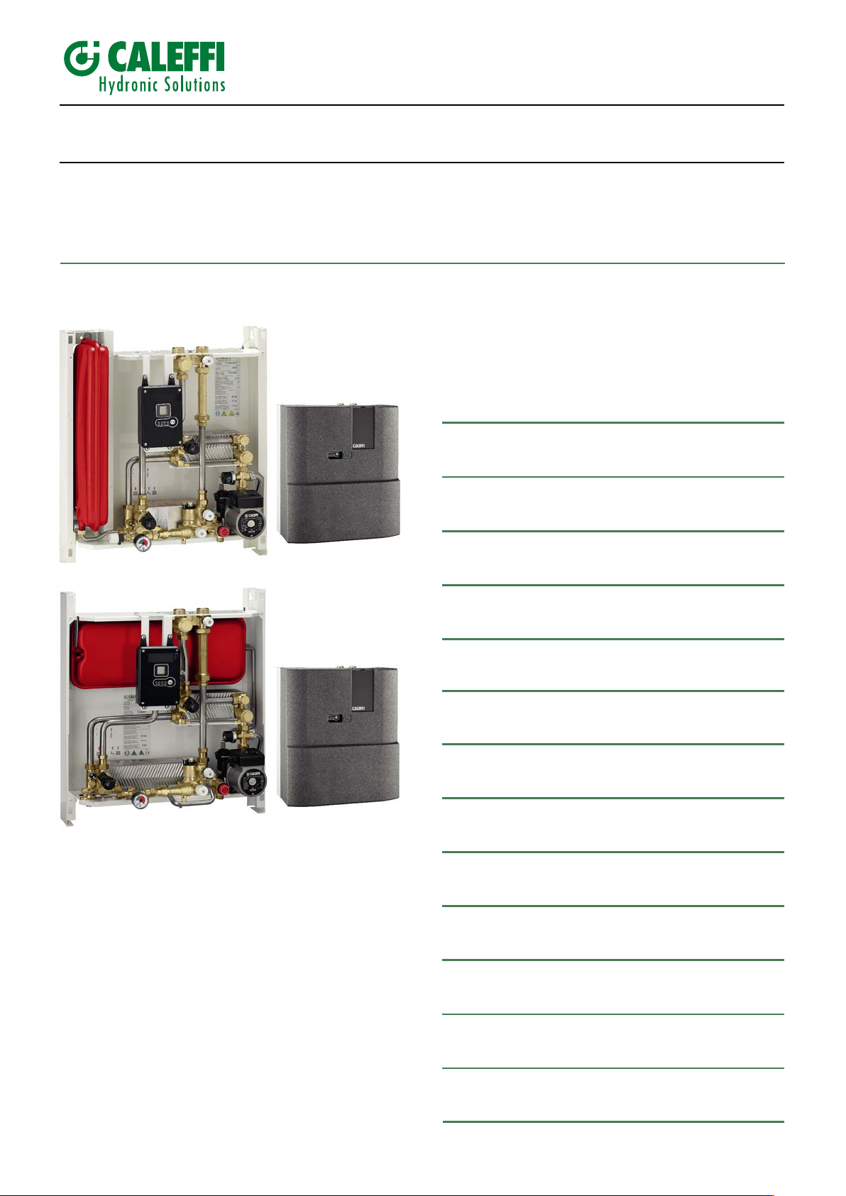
Wall-mounted compact indirect heat interface unit
SATK30 series
INSTRUCTIONS FOR INSTALLATION, COMMISSIONING AND MAINTENANCE
Function
The SATK series HIU allows independent control of heat regulation and
domestic hot water production within centralised heating systems or
served by district heating networks.
CONTENTS
78232.01EN
Safety instructions
Dimensions
Technical specifications
Installation
Commissioning
Electronic regulator
Operating cycles
Safety and alarms
SATK30103HE
2
3
4
6
7
8
9
10
Product range
SATK30103HE Indirect wall-mounted compact HIU for
instantaneous domestic hot water production,
power capacity 40 kW.
SATK30105HE Indirect wall-mounted compact HIU for
instantaneous domestic hot water production,
power capacity 65 kW.
SATK30105HE
Maintenance
Electric connections
Troubleshooting
Commissioning checklist
1
11
12
13
14
16
Page 2

SAFETY INSTRUCTIONS
WARNINGS
1 The device must be installed, commissioned and maintained by qualified technical personnel in accordance with national regulations and/or relevant local
requirements.
2 If the device is not installed, pre-run checked and maintained correctly in accordance with the instructions provided in this manual, it may not work properly and
may endanger the user.
3 Clean the pipes of any particles, rust, incrustations, limescale, welding slag and any other contaminants. The hydraulic circuit must be clean.
4 Make sure that all connection fittings are watertight.
5 When connecting water pipes, make sure that threaded connections are not mechanically overstressed. Over time this could result in breakage, with water leaks
causing damage and/or injury.
6 Water temperatures higher than 50°C may cause severe burns. When installing, commissioning and maintaining the device, take the necessary precautions so
that these temperatures will not be hazardous for people.
7 In the case of particularly hard or impure water, the device must be fitted for filtering and
legislation. Otherwise the device may be damaged and will not work properly.
8 Any use of the device other than its intended use is prohibited.
9 Any combination of the device with other system components must be made taking the operational characteristics of both units into consideration. 10 An incorrect
coupling could compromise operation of the device and/or system.
IMPORTANT: Risk of electric shock. Live parts. Shut off the electric supply before opening the device box.
1 During installation and maintenance operations, always avoid direct contact with live or potentially hazardous parts.
2 The device must not be exposed to water drops or humidity, direct sunlight, the elements, heat sources or high intensity electromagnetic fields. This device cannot
be used in areas at risk of explosion or fire.
3 The device must be connected to an independent bipolar switch. If work has
automatic or time reset, or which may be reset accidentally.
4 Use suitable automatic protection devices in accordance with the electrical characteristics of the region where the device is installed and in compliance with current
legislation.
5 The device must always be earthed before it is connected to the electric supply. If the device has to be removed, always disconnect the earth connection after
disconnecting the electric supply conductors. Check that the earth connection has been made to the highest of standards under applicable legislation.
6 Electrical installation must only be carried out by a qualified technician, in accordance with legal requirements.
7 The device does not contain asbestos or mercury.
8 The device is not designed for use by persons of reduced mental, physical or sensory capacity (including children) or persons lacking experience, unless they are
supervised or instructed in use of the device by a person responsible for their personal safety.
These instructions must be read and understood before installing and maintaining the device.
IMPORTANT! FAILURE TO FOLLOW THESE INSTRUCTIONS COULD RESULT IN A SAFETY HAZARD!
treating the water before it enters the device,
to be done on the device, cut off
the electric supply first. Do not use devices with
in accordance with current
NOTES:
1 Install water hammer arresters to compensate for any overpressure in the domestic water circuit;
2 In the presence of hot water recirculation or if non-return valves are fitted on the domestic cold water inlet, provision must be made to accommodate expansion of
the water contained in the system and in the heat interface unit;
3 All hydraulic connections must be checked before pressurising the system. Vibration during transport may cause the connections to become loose. DO NOT APPLY
EXCESSIVE TIGHTENING TORQUE otherwise the components may be damaged.
For the updated version of the technical documentation refer to www.caleffi.com.
LEAVE THIS MANUAL AS A REFERENCE GUIDE FOR THE USER. DISPOSE OF THE PRODUCT IN COMPLIANCE WITH CURRENT LEGISLATION
THE MANUFACTURER RESERVES THE RIGHT TO CEASE PRODUCTION AT ANY TIME AND TO MAKE ANY CHANGES DEEMED USEFUL OR
NECESSARY WITHOUT THE OBLIGATION OF PRIOR NOTICE.
2
Page 3
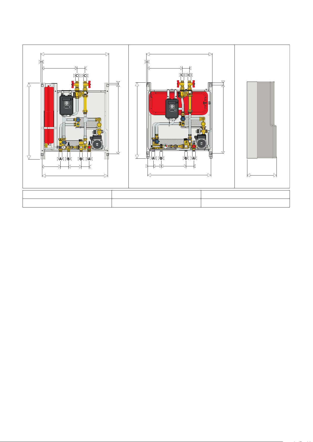
Dimensions
ON DHW CH FAULT
2
1
65
630
65 101
65
10
550
159
530
565 15
292,5
SATK30105HE
SATK30103HE
A B C
3/4” M 1/2” M 3/4” F
ON DHW CH FAULT
2
1
0
1
2
3
4
bar
65
10
550
630
565 15
65 207
65
59
530
298,5
265
Technical specifications SATK30103HE
Medium: water
Maximum percentage of glycol: 30%
Maximum medium temperature: 85°C
Max. working pressure: - primary circuit: 1,6 MPa (16 bar)
Nominal DHW exchanger capacity: 40 kW
Nominal heating exchanger capacity: 15 kW
Maximum recommended primary circuit flow rate: 1,2 m
Maximum differential pressure on
domestic water modulating valves: Dp 90 kPa (0,9 bar)
Domestic water circuit max. flow rate: 18 l/min (0,3 l/s)
Minimum flow to activate domestic water flow meter: 2,7 l/min ±0,3
Electric supply: 230 V (ac) ±10% 50 Hz
Max power consumption: 80 W
Protection class: IP 40
Pump: UPM3 15-70
Pump by-pass setting: 45 kPa (0,45 bar)
Actuators: stepper 24 V
Probes: NTC 10 kΩ
Safety relief valve setting: 0,3 MPa (3 bar)
Safety thermostat: 55°C ±3
Expansion vessel: - capacity: 7 l
Pressure switch: - opening: 40 kPa (0,4 bar)
Materials
Components: brass EN 12165 CW617N
Fitting pipes: steel
Frame: RAL 9010 painted steel
Protective shell cover: EPP
Heat exchanger: brazed stainless steel
- secondary circuit: 0,3 MPa (3 bar)
- domestic water circuit: 1 MPa (10 bar)
- pre-charge value: 0,1 MPa (1 bar)
- closing: 80 kPa (0,8 bar)
Technical specifications SATK30105HE
Medium: water
Maximum percentage of glycol: 30%
Maximum medium temperature: 85°C
Max. working pressure: - primary circuit: 1,6 MPa (16 bar)
- secondary circuit: 0,3 MPa (3 bar)
- domestic water circuit: 1 MPa (10 bar)
Nominal DHW exchanger capacity: 65 kW
3
/h
Nominal heating exchanger capacity: 15 kW
Maximum recommended primary circuit flow rate: 1,2 m
3
/h
Maximum differential pressure on
domestic water modulating valves: Dp 165 kPa (1,65 bar)
Domestic water circuit max. flow rate: 27 l/min (0,45 l/s)
Minimum flow to activate domestic water flow meter: 2,7 l/min ±0,3
Electric supply: 230 V (ac) ±10% 50 Hz
Max power consumption: 80 W
Protection class: IP 40
Pump: UPM3 15-70
Pump by-pass setting: 45 kPa (0,45 bar)
Actuators: stepper 24 V
Probes: NTC 10 kΩ
Safety relief valve setting: 0,3 MPa (3 bar)
Safety thermostat: 55°C ±3
Expansion vessel: - capacity: 7 l
- pre-charge value: 0,1 MPa (1 bar)
Pressure switch: - opening: 40 kPa (0,4 bar)
- closing: 80 kPa (0,8 bar)
Materials
Components: brass EN 12165 CW617N
Fitting pipes: steel
Frame: RAL 9010 painted steel
Protective shell cover: EPP
Heat exchanger: brazed stainless steel
3
Page 4
Installation
The SATK series HIU is designed for installation in a sheltered
domestic environment (or similar), therefore cannot be installed or
used outdoors, i.e. in areas directly exposed to atmospheric
agents. Outdoor installation may cause malfunctioning and
hazards.
If the device is enclosed inside or between cabinets, sufficient
space must be provided for routine maintenance procedures. It is
recommended that electrical devices are NOT placed underneath
the HIU, as they may be damaged in the event of safety relief valve
activation if not connected to a discharge tundish, or in the event of
leaks occurring at the hydraulic fittings. If this advice is not heeded,
the manufacturer cannot be held responsible for any resulting
damage.
In the event of a malfunction, fault or incorrect operation, the device
should be deactivated; contact a qualified technician for
assistance.
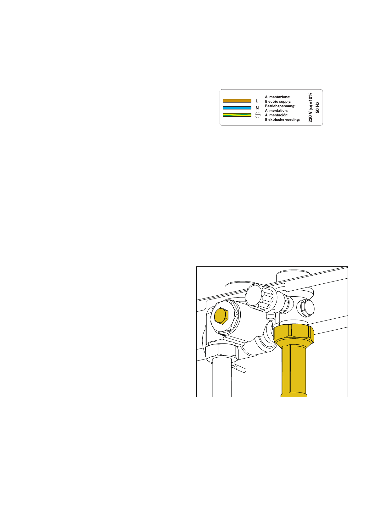
Connection to the main supply
The device is supplied with an electric supply cable which is not
fitted with a plug.
The device should be electrically connected to a 230 V (ac) singlephase + earth mains supply using the three-wire cable marked with
the label as specified below, observing the LIVE (L) - NEUTRAL (N)
polarities and the earth connection. This line must be connected to
a circuit breaker device.
Preparation
After having established the point where the device has to be
installed, perform the following operations:
· Mark the holes required for securing the HIU to the wall
· Mark the position of the hydraulic connections
Check the measurements again and begin laying the following
lines:
• Hydraulic:
1. connection to the central system line
2. heating circuit connection
3. domestic water circuit connection
4. conveyance of safety relief valve and charging unit backflow
preventer discharge
• Electric:
1. 230 V (ac) – 50 Hz electric supply line
2. chrono-thermostat/thermostat line (potential-free)
3. centralised bus line for heat meter data transmission (if required)
4. centralised electric supply line for heat meter (if required)
Before installation, it is recommended to carry out accurate flushing
of all the pipes of the system in order to remove any residue or
impurities that could endanger correct operation of the HIU.
Fix the HIU to the wall.
N.B.: the wall anchors (not supplied) can only guarantee effective
support if inserted correctly (in accordance with good technical
practice) into walls built using solid or semi-solid bricks. If working
with walls built using perforated bricks or blocks, mobile dividing
panels or any masonry walls other than those indicated, a
preliminary static test must be carried out on the support system.
Heat meter installation
The HIU is designed to fit a compact heat meter (with incorporated
return probe) with 1” threaded connections and 130 mm gauge.
Before carrying out any maintenance, repair or part replacement
work, proceed as follows:
- cut off the electric supply
- remove the cover
- close the shut-off valves
- empty the HIU using the drain cocks provided
- remove the template (A)
- remove the cap (B)
- install the flow meter on the return pipe
- install the flow probe in the M10 pocket (B).
Please refer to the heat meter technical data sheets for further
information.
B
A
Electric connections
Make sure that the electrical system can withstand the maximum
power consumption of the appliance, with particular emphasis on
the cross-section of the cables.
If you have any doubts, contact a qualified technician to request a
thorough check of the electrical system.
Electrical safety of the appliance is only achieved when it is
correctly connected to an effective earthing system, constructed as
specified in current safety regulations. This is a compulsory safety
requirement.
4
Page 5
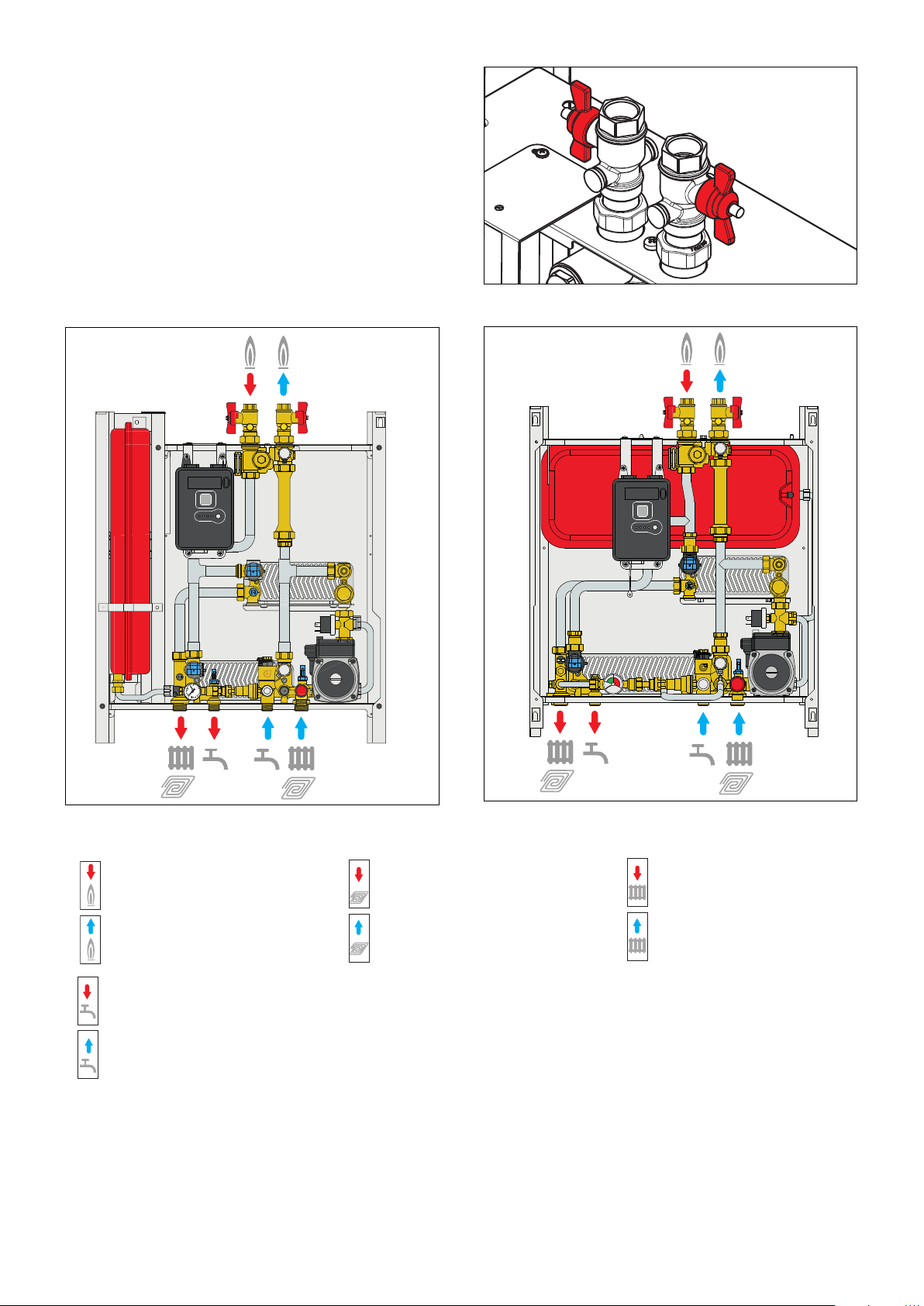
Hydraulic connections
ON DHW CH FAULT
2
1
0
1
2
3
4
bar
ON DHW CH FAULT
2
1
Primary circuit flow
Primary circuit return
Domestic hot water outlet
Domestic cold water inlet
Low temperature circuit flow
Low temperature circuit return
High temperature circuit flow
High temperature circuit return
Hydraulic connections to the centralised line must be implemented
using the manual shut-off valves supplied with the HIU, which allow
any necessary maintenance work to take place without having to
empty the centralised system.
It is advisable to install manual shut-off valves (not supplied) also
on the bottom connections to the apartment circuits.
Before installation, it is recommended to carry out accurate flushing
of all the pipes of the system in order to remove any residue or
impurities that could endanger correct operation of the HIU.
In order to facilitate these operations a manual bypass flushing
valve is available (code 789100).
N.B. Install the valves as shown in the figure
Key to symbols
NOTES:
1 Install water hammer arresters to compensate for any overpressure in the domestic water circuit;
2 In the presence of hot water recirculation or if a non-return valve is fitted into the domestic cold water inlet, provision must be made to
accommodate the expansion of the water contained within the system and the heat interface unit;
3 All hydraulic connections must be checked before pressurising the system. Vibration during transport may cause the connections to become loose.
DO NOT APPLY EXCESSIVE TIGHTENING TORQUE otherwise the components may be damaged.
5
Page 6

Connection to the chrono-thermostat
Raumthermostat
(Potenzialfreier Kontakt)
Sonde d’ambiance
(Contact sec)
Termostato de ambiente
(Contacto sin potencial)
Ruimtesensor
(Schoon contact)
WARN ING !
DO NOT CONNECT EXTERNAL
VOLTAGE SUPPLY TO THESE
TERMINALS
ATT ENZ IO NE!
NON ALIMENTARE IN TENSIONE
Termostato ambiente
(Contatto pulito)
Room thermostat
(Volt free connection)
The SATK series HIU is fitted for connection to a thermostat or
chrono-thermostat, both standard and OpenTherm, for ambient
temperature adjustment.
The connection to this device (potential-free contact) must be
made with the two-wire cable marked with the label shown below.
Should it be necessary to extend this cable, use one with the same
cross-section (max 1 mm
2
) and maximum length 30 m.
Fitting the cover
Place the casing over the frame, inserting the upper tabs (1) into
the corresponding slots (2).
Place the lower part of the casing over the frame.
Tighten the screws (3).
2
Commissioning
Filling the central heating system
Open the shut-off valves on the connections to the centralised line
and, in the central heating system, proceed with charging the
system to the design pressure.
Once these procedures are complete, vent the system and check
its pressure again (repeat the filling process if necessary)
Vessel pre-charge check
Perform the following steps:
- Use a pressure gauge to check the pre-charge value
- If necessary, restore the pre-charge value shown in the technical
specifications.
Filling the user system
SATK30 series HIU are fitted with a filling unit equipped with a
backflow preventer (C), check valve (D) and cock (A).
When filling the system for the first time or for subsequent top-up
procedures following a heating circuit
pressure switch fault, restore the system pressure
(0,12–0,2 MPa - 1,2–2 bar) by opening cock (A) and checking the
value by means of the pressure gauge (B).
Once the correct pressure has been reached, close the cock (A),
vent the system and check its pressure again (repeat the filling
process if necessary)
1
C
A
B
System start-up
Before starting the HIU, visually check the hydraulic connection
watertightness and the electric wiring. After finishing the check,
activate the electric supply to the HIU and check for the presence
of any error signals.
If there are any, eliminate the fault indicated and proceed as
described below, setting the set point of the domestic water and
heating cycles, programming the thermostat/chrono-thermostat
D
3
according to the desired temperatures and times, and checking the
operating cycles.
6
Page 7

88
Electronic regulator
123456
User interface
The user interface, built into the PCB, consists of the following
devices:
• LED indicator
The various functions and faults are signalled by either flashing or
steady illumination of the LEDs.
ON - Electric supply 230 V (ac)
DHW - Domestic cycle
CH - Heating cycle
FAULT - Fault detected
• RESET key
This allows restoration of normal function after the safety thermostat
has been triggered and activation/deactivation of the floor slab
heating function.
Operating principle
All heating and domestic hot water functions offered by SATK30
series HIUs are controlled by a digital temperature regulator.
Automatic controller functions
• Reset diverter/modulating valve to zero
Immediately after the power supply has been switched on, the
position of the modulating valves is reset to zero.
• Pump anti-seizing
When the pump is not in use, it is powered on for a period of
5 seconds every 24 hours.
Diverter/modulating anti-seizing cycle
The anti-seizing cycle for the diverter/modulating valve is run every
24 hours.
• Trimmers for set point settings
They allow the setting of the temperature set-point for the operating
cycles and view the relative value on the display.
Heating cycle
Not used
• LCD display
Shows programmed set-point temperatures and error codes.
• Dip switches
Allow set-up of the various models and enabling of optional
functions
7
Page 8

5
ON
1
OFF
48
60
25
48
60
Operating cycles
Domestic cycle
This cycle always takes priority over the heating cycle.
When DHW cycle activation is requested, due to DHW tapping by
the user (detected by the domestic water flow meter), the regulator
modulates the valve opening in order to adjust the temperature
detected by the domestic water probe to the selected set point
value.
When tapping ends, the modulating valve is fully closed.
The active domestic hot water cycle is signalled by yellow DHW
LED steady on.
The general domestic water cycle temperature set point can be set
using trimmer P1 and shown on the display.
Heating cycle
Set point regulation
When heating cycle activation is requested by the room thermostat,
the circulation pump is powered while the modulating valve is
opened gradually until the set point temperature is reached.
At the end of the heating cycle, the circulation pump comes to a
stop and the modulating valve is closed. The active heating cycle is
signalled by lighting of the yellow CH LED.
The heating cycle temperature set point can be set using trimmer P2
and shown on the display.
Floor slab heating function
LOW temperature setting
Facilitates the installation of underfloor heating systems at low
temperatures. This function can only be activated and executed if
there are no faults.
It can be activated by pressing and holding the RESET button for 8
seconds.
The yellow CH LED blinks while the floor slab heating function is in
operation.
The function lasts 240 hours and is carried out by simulating a
request to run in heating mode starting from a set point of 25°C and
rising in regular intervals to a temperature of 45°C. Once the
maximum set point has been reached, the function is executed,
following the same procedures, in reverse (from the maximum set
point to the minimum set point).
This function has priority over heating and hot water cycles, and
can be suspended at any time by pressing and holding the RESET
button for 8 seconds.
8 seconds
Optional functions (to activate/deactivate the optional functions
the electric power supply must always be turned off!)
Domestic cycle
DHW pre-heating function
The function is enabled by setting DIP switch 5 to the ON position.
During periods when the domestic water cycle is not used, if the
DHW probe detects a temperature 10°C below the SET value, the
controller partially opens the domestic hot water modulating valve for
the time required (max. 5 min.) to bring the exchanger to the
condition wherein it can assure rapid DHW production.
The domestic hot water pre-heating function is signalled by the
flashing yellow DHW LED.
This function is less of a priority than any domestic water or heating
cycles.
Heating cycle
Modulating temperature regulation with compensated set
point
The function is enabled by setting DIP switch 1 to the OFF position.
When the function is enabled, the flow temperature is modified
according to the temperature detected by the compensation probe
(located on the user return pipe). This keeps the actual thermal
output of the slab - and therefore the ambient thermal load - under
control. The thermal response time of the system is thus minimised.
If the function is enabled the display shows the return temperature,
and the flow temperature is adjusted in accordance with the
following formula:
Flow temperature = Return temperature +
In MEDIUM/HIGH temperature configuration: DT = 8–22°C
At LOW temperature setting: DT = 2–8°C
D
T
8
Page 9

Safety and alarms
69
5
6
79
80
4
Error codes associated with faults signalled by illumination of the
FAULT LED are also shown on the display.
Heating circuit pressure switch fault
Error code 4
The electronic regulator continuously monitors the status of the
pressure switch controlling the water pressure in the heating circuit.
If the pressure switch is activated, the heating circulation pump
immediately comes to a stop and the modulating valve is completely
closed.
This fault implies the stoppage of the heating cycle only.
Domestic water drawing requests will continue to be served normally.
N.B.: A low pre-charge value of the expansion vessel can cause a
pressure switch fault.
Removing a fault
Return to the operating mode is subordinate to restoration of the
correct water pressure in the secondary heating circuit (see page
6 - “Filling the user system”).
Probe fault
If a temperature probe fails, the associated cycle will be stopped
immediately and disabled.
Any requests to run cycles not associated to the previous one will
continue to run normally.
Safety thermostat cut-out
Error code 69
The HIUs configured to support low temperature heating
continuously monitor the safety thermostat controlling the flow
temperature.
If the safety thermostat is activated during a general cycle, the
heating circulation pump immediately comes to a stop and the
modulating valve is completely closed.
After the user has removed the block imposed by the safety
thermostat, operation can only be re-enabled when the modulating
valves are completely closed again.
This means that if a domestic water cycle is in progress, the
activation of the shut-off valve will be postponed until the end of that
domestic water cycle.
Removing a fault
To restore the operating mode press the manual
RESET button.
Incorrect switch setting
Error code 79
Heating probe fault
Error code: 5
Domestic water probe fault
Error code: 6
Compensation probe fault
Error code: 15
Removing a fault
Restore the correct switch setting in accordance with the
procedure shown on pages 10-11.
Incorrect switch setting (heat interface unit disabled)
Error code 80
Removing a fault
The heat interface unit is disabled due to incorrect setting of the
dip-switches. Restore the correct switch setting in accordance with
the procedure shown on pages 10-11.
Removing a fault
Normal operating conditions are restored automatically once the
faulty probe is working properly again (see page 12 - “Temperature
probe replacement”).
9
Page 10

ON DHW CH FAULT
2
1
0
1
2
3
4
bar
SATK30103HE Indirect HIU with high-efficiency pump. 40 kW DHW.
1
2
3
564
ON
1
2
3
5
6
ON
4
Characteristic components
1. Frame
2. Expansion vessel
3. Electronic regulator
4. 2-way modulating valve (primary heating)
5. Heating flow temperature probe (secondary)
6. DHW heat exchanger
7. 2-way modulating valve - DHW
8. Thermal safety thermostat
9. DHW temperature probe
10. Secondary heating drain cock
11. Filling unit with backflow preventer
12. Safety relief valve
13. Flow temp. compensation return probe
14. Primary circuit drain cock
15. Pump UPM3 15-70
16. Protective by-pass
17. DHW priority flow meter
18. Pressure switch
19. Secondary heating strainer
20. Heating exchanger
21. Heat meter spacer template
22. Primary circuit strainer/flow probe pocket
23. Primary air vent cock
24. Primary circuit shut-off valves
Functional characteristics
Heating range
- LOW temperature setting 25–45°C
- MEDIUM/HIGH temperature setting 45–75°C
Set point regulation
DHW production range 42–60°C
Optional functions
Domestic cycle: - DHW pre-heating function
Heating cycle: - modulating temperature regulation
with compensated set point
at LOW temperature setting:
- floor slab heating function
Factory settings
The SATK30103HE HIU is factory set to support low temperature
heating (25–45°C), according to the following switch setting.
To modify the factory settings and enable the HIU to support
medium/high temperature systems (45–75°C), proceed as follows.
1 - cut off the electric power supply to the HIU
2 - set switches 2-3 according to the following setting:
3 - disconnect the thermal safety thermostat (see page 13 ref.
5) and apply a jumper on the cable (see adjacent diagram)
4 - restore the electric supply.
OFF
Factory set (do not change)
ON
OFF
ON
May be changed to activate optional functions
Switch 1: modulating temperature regulation
with compensated set point
Switch 2-3: HIGH - LOW temperature setting
Switch 5: DHW pre-heating function
10
Page 11

ON DHW CH FAULT
2
1
0
1
2
3
4
bar
20
11
14
19
18
17
15
16
13
12
23
21
22
3
9
4
7
10
8
6
5
2
1
24
SATK30105HE Indirect HIU with high efficiency pump. 65 kW DHW.
1
2
3
564
ON
1
2
3
5
6
ON
4
Characteristic components
1. Frame
2. Expansion vessel
3. Electronic regulator
4. 2-way modulating valve (primary heating)
5. Heating flow temperature probe (secondary)
6. DHW heat exchanger
7. 2-way modulating valve - DHW
8. Thermal safety thermostat
9. Secondary heating drain cock
10. DHW temperature probe
11. Filling unit with backflow preventer
12. Safety relief valve
13. Flow temp. compensation return probe
14. Primary circuit drain cock
15. Pump UPM3 15-70
16. Protective by-pass
17. Pressure switch
18. Heating strainer (secondary)
19. DHW priority flow meter
20. Heating exchanger
21. Heat meter spacer template
22. Primary circuit strainer/flow probe pocket
23. Primary air vent cock
24. Primary circuit shut-off valves
Functional characteristics
Heating range
- LOW temperature setting 25–45°C
- MEDIUM/HIGH temperature setting 45–75°C
Set point regulation
DHW production range 42–60°C
Optional functions
Factory settings
The SATK30105HE HIU is factory set to support low temperature
heating (25–45°C), according to the following switch setting.
Domestic cycle: - DHW pre-heating function
Heating cycle: - modulating temperature regulation
with compensated set point
at LOW temperature setting:
- floor slab heating function
To modify the factory settings and enable the HIU to support
medium/high temperature systems (45–75°C), proceed as
follows.
1 - cut off the electric power supply to the HIU
2 - set switches 2-3 according to the following setting:
3 - disconnect the thermal safety thermostat (see page 13
ref. 5) and apply a jumper on the cable (see adjacent
diagram)
4 - restore the electric supply.
OFF
Factory set (do not change)
ON
OFF
ON
May be changed to activate optional functions
Switch 1: modulating temperature regulation
with compensated set point
Switch 2-3: HIGH - LOW temperature setting
Switch 5: DHW pre-heating function
11
Page 12

Maintenance
All maintenance procedures should be carried out by an authorised
technician.
Regular maintenance guarantees better efficiency and helps to
save energy.
Before carrying out any maintenance, repair or part replacement
work, proceed as follows:
- Cut off the electric supply
- Remove the cover
- Close the shut-off valves
- Empty the HIU using the drain cocks provided.
Heat exchanger replacement
- Remove the heat exchanger, loosening the 2 hex socket head
screws fixing it in place (A)
- Replace the heat exchanger and the O-rings.
- Tighten the two fixing screws (A).
N.B. The pins fixing the heat exchanger are positioned in such a way
as to allow it to be placed only in the correct direction.
Replacing the valve obturator
- Extract the fixing clip (D) and then the actuator
- Position the new actuator (E)
- Insert the fixing clip, respecting the correct direction
- Reconnect the connector.
D
E
Replacing the valve obturator
- Disconnect the valve actuator (see previous paragraph)
- Extract the obturator by unscrewing the locking nut (F)
- Replace the obturator, screw on the locking nut (F) and then fit
the actuator
- Insert the fixing clip, respecting the correct direction
- Reconnect the connector.
A
Strainer cleaning
All heat interface units have a strainer on the inlet for water from the
centralised system.
To clean these strainers, carry out the following maintenance
procedure:
- Unscrew the cap (B)
- Remove the strainer mesh and discard any impurities
- Refit the strainer mesh
- Refit the cap and tighten it.
A
B
Temperature probe replacement
- Disconnect the probe cable by bending tab (C) slightly
and extracting the connector (see page 13, ref. 1-3-7)
- Unscrew the probe
- Fit the new probe
- Reconnect the connector respecting the only possible way it can
be inserted.
F
Replacing the DHW priority flow meter
- Disconnect the flow meter cable acting on the connector (see
page 13, ref. 2)
- Extract the flow sensor (G)
- Position the new sensor
- Reconnect the connector respecting the only possible way it can
be inserted.
G
Replacing or cleaning the DHW priority flow meter turbine
Extract the flow sensor
- Unscrew and remove the cartridge (H)
- Remove any impurities or change the cartridge if necessary
- Screw the cartridge back into place
- Refit the flow sensor
H
C
Vessel pre-charge check
For correct operation of the system periodically check (at least
once every six months) the vessel pre-charge value.
When carrying out maintenance on the electrical part, for the
connections follow the diagram on page 13.
After concluding maintenance, proceed with the filling and
checking operations described in the chapter “Commissioning”
and fit the cover.
If you require any information regarding spare parts, please contact
Caleffi spa.
12
Page 13

Electric connections
FUSE 5x20
1
2 3
4
6
5
9
10
13
11
12
6 35
4 21
14
s5SARESOLOPERCOLLEGAMENTOACOD
s5SETHISWIREFORCONNECTIONTOCODEONLY
s°NgUTILISERQUEPOURLALIAISONAVECCODE
s6ERWENDEN3IEDIESES'ERËTNURZUM!NSCHLUSS
ANDIE!RT.R
s'EBRUIKDEZEENKELVOORAANSLUITINGOPCODE
s5TILICESOLAMENTEPARALACONEXIØNCONCOD
s5SARESOLOPERCOLLEGAMENTOACOD
s5SETHISWIREFORCONNECTIONTOCODEONLY
s°NgUTILISERQUEPOURLALIAISONAVECCODE
s6ERWENDEN3IEDIESES'ERËTNURZUM!NSCHLUSS
ANDIE!RT.R
s'EBRUIKDEZEENKELVOORAANSLUITINGOPCODE
s5TILICESOLAMENTEPARALACONEXIØNCONCOD
7
8
Raumthermostat
(Potenzialfreier Kontakt)
Sonde d’ambiance
(Contact sec)
Termostato de ambiente
(Contacto sin potencial)
Ruimtesensor
(Schoon contact)
Termostato ambiente
(Contatto pulito)
Room thermostat
(Volt free connection)
1
2
3
4
5
6
7
8
9
10
11
12
13
14
DHW temperature probe
DHW priority flow meter
Flow temp. compensation return probe
DHW production valve actuator
Thermal safety thermostat
Pressure switch
Heating flow temperature probe
Heating valve actuator
Earth
Pump
Electric supply 230V (ac)*
Room thermostat*
Fuse
HIU enabling
* Wiring to be made during installation
(Room thermostat not supplied)
(potential-free line)
MAX 30 m
13
Page 14

Troubleshooting
FAULT DESCRIPTION INDICATIONS POSSIBLE CAUSE OF FAULT OPERATIONS TO BE PERFORMED
primary circuit shut-off valves closed open the valves
modulating valve actuator connector disconnected reconnect actuator connector
modulating valve actuator disconnected from valve body reconnect actuator
call qualified personnel to have it
restore correct connection
call qualified personnel to have it
call qualified personnel to have it
call qualified personnel to have it
call qualified personnel to have it
call qualified personnel to have it
call qualified personnel to have it
call qualified personnel to have it
call qualified personnel to have it
call qualified personnel to have it
restore correct connection
call qualified personnel to have it
restore correct connection
call qualified personnel to have it
call qualified personnel to have it
call qualified personnel to have it
call qualified personnel to have it
replaced
replaced
replaced
replaced
replaced
replaced
serviced
serviced
replaced
replaced
replaced
replaced
replaced
replaced
serviced
Water is not
heated
The water is hot
but does not
reach the
desired
temperature
Hot water
temperature is
too high
DHW LED ON
FAULT LED ON+
error code 6 active
FAULT LED ON+
error code 79 active
F
AULT LED ON+
error code 80 active
DHW LED OFF
all LEDs are OFF
DHW LED ON
DHW LED ON
modulating valve actuator faulty
DHW temperature probe cable inverted with heating
probe
presence of air in the system vent the system
electronic controller not working
valve obturator blocked in closed position
centralised system not working/cold contact person in charge of system
DHW temperature probe disconnected reconnect probe
DHW temperature probe faulty
incorrect switch setting restore correct switch setting
incorrect switch setting restore correct switch setting
DHW priority flow meter disconnected reconnect flow meter
DHW priority flow meter faulty
no electric power supply restore HIU electric supply
protection fuse burnt out
domestic water cycle temperature set point too low increase set point
primary circuit strainer of the HIU clogged
heat exchanger partly clogged
modulating valve actuator faulty
valve obturator blocked in intermediate position
modulating valve actuator connector disconnected reconnect actuator connector
DHW temperature probe cable inverted with heating
probe
excessive demand for DHW decrease demand
electronic controller not working
centralised system temperature insufficient contact person in charge of system
primary circuit flow rate insufficient contact person in charge of system
domestic water cycle temperature set point too high decrease set point
DHW temperature probe cable inverted with heating
probe
modulating valve actuator faulty
valve obturator blocked in intermediate or open position
electronic controller not working
primary circuit excessive pressure contact person in charge of system
HIU strainer clogged
Hot water flow
rate is
insufficient
Hot water flow
rate is zero
DHW LED ON
DHW LED OFF
possible domestic water system shut-off valves
centralised domestic circuit cold water flow rate
possible domestic water system shut-off valves closed open the valves
no cold water in centralised domestic circuit
HIU strainer completely clogged
heat exchanger completely blocked
partially closed
call qualified personnel to have it
insufficient
call qualified personnel to have it
call qualified personnel to have it
call qualified personnel to have it
open the valves
serviced
serviced
serviced
serviced
14
Page 15

FAULT DESCRIPTION INDICATIONS POSSIBLE CAUSE OF FAULT OPERATIONS TO BE PERFORMED
heating cycle temperature set point too low increase set point
check programming of
chrono-thermostat
call qualified personnel to have it
serviced
call qualified personnel to have it
replaced
call qualified personnel to have it
replaced
restore correct connection
call qualified personnel to have it
replaced
call qualified personnel to have it
replaced
check programming of chrono-
thermostat
call qualified personnel to have it
replaced
The room is not
reaching the
desired
temperature
CH LED ON
CH LED OFF
all LEDs are OFF
FAULT LED ON +
error code 4 active
chrono-thermostat temperature setting incorrect
HIU strainer clogged
heating valve actuator faulty
heating valve obturator blocked
modulating valve actuator connector disconnected reconnect actuator connector
DHW temperature probe cable inverted with heating
probe
presence of air in the system vent the system
pump not working
pump cable not connected restore connection
possible system shut-off valves/terminals closed open the valves
centralised system temperature insufficient contact person in charge of system
electronic controller not working
primary circuit flow rate insufficient contact person in charge of system
centralised system not working contact person in charge of system
chrono-thermostat time setting incorrect
chrono-thermostat not working check chrono-thermostat
no electric power supply restore HIU electric supply
protection fuse burnt out
heating circuit pressure too low restore system pressure
Start-up of the
heat interface
unit heating
function triggers
the safety circuit
breaker
FAULT LED ON +
error code 5 active
FAULT LED ON +
error code 15 active
FAULT LED ON +
error code 69 active
FAULT LED ON +
error code 79 active
F
AULT LED ON +
error code 80 active
All LEDs are OFF pump cable connector inserted the wrong way round
heating temperature probe faulty
compensation temperature probe faulty
safety thermostat cut-out
incorrect switch setting restore correct switch setting
incorrect switch setting restore correct switch setting
call qualified personnel to have it
replaced
call qualified personnel to have it
replaced
call qualified personnel to have it
serviced
check that the pump cable connector is
inserted the right way round
15
Page 16

Commissioning checklist
Checks to be performed
1 Is the heat interface unit properly secured to the wall?
2 Has the system flushing been carried out?
3 Check strainers and clean them if necessary
4 Is the heat meter (if present) connected?
5 Is the heat meter (if present) connected to the building datalogger (if required)?
6 Is the DCW line fitted with a pressure reducing valve?
7 Is the system protected by water hammer arresters?
8 Has the domestic exchanger pre-heating function (normally off) been activated (if required)?
9
Has the modulating temperature regulation with compensated set point (normally off) been
activated (if required)?
10 Is the heat interface unit connected to the 230 V (ac) electric supply?
11 Is the room thermostat (potential-free contact) connected?
12
Has the visual inspection of the HIU internal electrical connections given a positive result and are
the connections compliant with specifications and made in accordance with best practices?
13 Are the shut-off valves open?
14 Has the visual inspection of the hydraulic connections given a positive result?
15 Has the system (primary) been filled and vented?
16 Has the system (secondary) been vented and filled to a pressure of between 1,2 and 2 bar?
17 Is the heat interface unit powered (green “ON” LED lit)?
18 No alarm code (“fault” LED lit) displayed on the heat interface unit regulator?
19
Has the DHW temperature been set to the required value?
(42–50°C recommended)
20 Has the heating flow temperature been set to a correct value?
21 Is the primary circuit at working temperature?
22 Check that “CH” LED lights approx. 10 seconds after the thermostat trips
23
24
25
Check that the pump operates correctly on tripping of the thermostat
(check that secondary flow pipes start to heat up)
Simulate minimal DHW tapping (approx 3 l/min) and check that “DHW” LED lights and that water
is supplied at the required temperature
Simulate abundant DHW tapping and check, by means of the installed heat meter, that the
primary circuit flow rate is sufficiently high
16
 Loading...