

Page 1
CALEFFI
www.caleffi.com
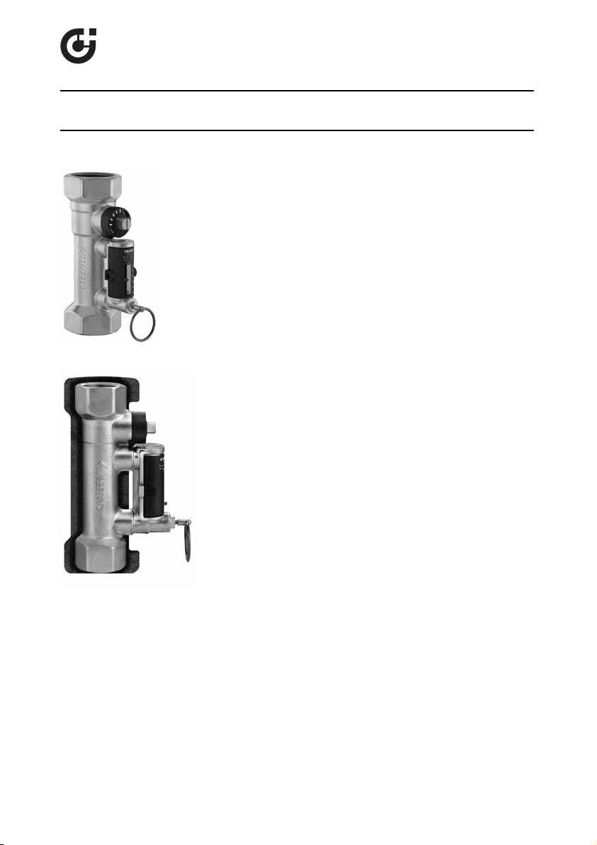
QuickSetter™ Balancing Valve with flow meter
18106.02
© Co pyrig ht 2011 C aleff i
132 Series
Function
The balancing valve accurately controls the flow rate of heating and
cooling transfer fluid supplied to fan coils and terminal units; or where
flow balancing is required in solar thermal systems. Proper hydronic
system balancing ensures the system operates according to design
specifications, providing satisfactory thermal comfort with low energy
consumption.
The flow meter is housed in a bypass circuit on the valve body and
can be shut off during normal operation. The flow meter permits
fast and easy circuit balancing without added differential pressure
gages and charts. The balancing valve comes standard with a hot
pre-formed insulation shell to optimize thermal performance for both
hot and chilled water.
Product range
132 Series Balancing valve with flow meter sizes 1/2”, 3/4”,
Technical characteristics
Valve
Material: Body and ball: brass
Ball control stem: chrome plated brass
Ball seal seat: PTFE
Control stem guide: PSU
Seals: EPDM
Flow meter
Material: Body: brass
Headwork: brass EN 12164 CW614N
Valve stem: chrome plated brass
Springs: stainless steel
Seals: EPDM
Flow meter float and indicator cover: PSU
Performance: Medium: water, glycol solutions
Flow rate correction factor: 20%-30% glycol solutions: 0.9
Insulation
Material: closed cell expanded PE-X
Thickness: 10 mm
Density: - inner part: 30 kg/m
- outer part: 50 kg/m
Thermal conductivity (DIN 52612): - at 0°C: 0.038 W/(m·K)
Coefficient of resistance to water vapor (DIN 52615): > 1.300
Working temperature range: 32 - 212°F (0–100°C)
Reaction to fire (DIN 4102): class B2
Patent application No. MI
1”, 1 1/4”, 1 1/2” and 2"
Max. percentage of glycol: 50%
Max. working pressure: 150 psi (10 bar)
Working temperature range: 14 - 230°F (-10–110°C)
Flow rate range unit of measurement: gpm
Accuracy: ±10%
Control stem angle of rotation: 90°
Required operating wrench: 1/2”–1 1/4”: 9 mm
Threaded connections: 1/2”– 2” FNPT
40%-50% glycol solutions: 0.8
- at 40°C: 0.045 W/(m·K)
2007A000703.
1 1/2” and 2”: 12 mm
3
3
Page 2
SAFETY INSTRUCTION
7
6
5
4
3
2
7
6
5
4
3
2
765
432
765
432
This safety alert symbol will be used in this manual to draw attention to safety related
instructions. When used, the safety alert symbol means ATTENTION! BECOME ALERT!
YOUR SAFETY IS INVOLVED! FAILURE TO FOLLOW THESE INSTRUCTIONS MAY
RESULT IN A SAFETY HAZARD.
CAUTION: All work must be performed by qualified personnel trained in the
proper application, installation, and maintenance of systems in accordance
with all applicable codes and ordinances.
CAUTION: Over-tightening and breakage can occur with the use of Teflon
®
pipe joint compounds. Teflon®provides lubricity so that care must be
exercised not to over-tighten joints. Failure to follow these instructions
could result in property damage and /or personal injury.
WARNING: System fluids are under pressure or temperature can be
hazardous. Be sure the pressure has been reduced to zero and the
system temperature is below 100°F (38°C). Failure to follow these
instructions could result in property damage and/or personal injury.
Caleffi shall not be liable for damages resulting from stress corrosion, misapplication or misuse of it products.
Installation
132 series
The balancing valves, with built-in flow meter, must be installed by
qualified technical personnel in accordance with the instructions given
in this manual and with current regulations.
Clean the pipes of any debris, rust, welding slag and any other
contaminants.
5D
132 series
As in all hydraulic circuits it is important to pay attention to the
cleanliness of the entire system.
Pump
For optimal operation, any air in the medium must be removed.
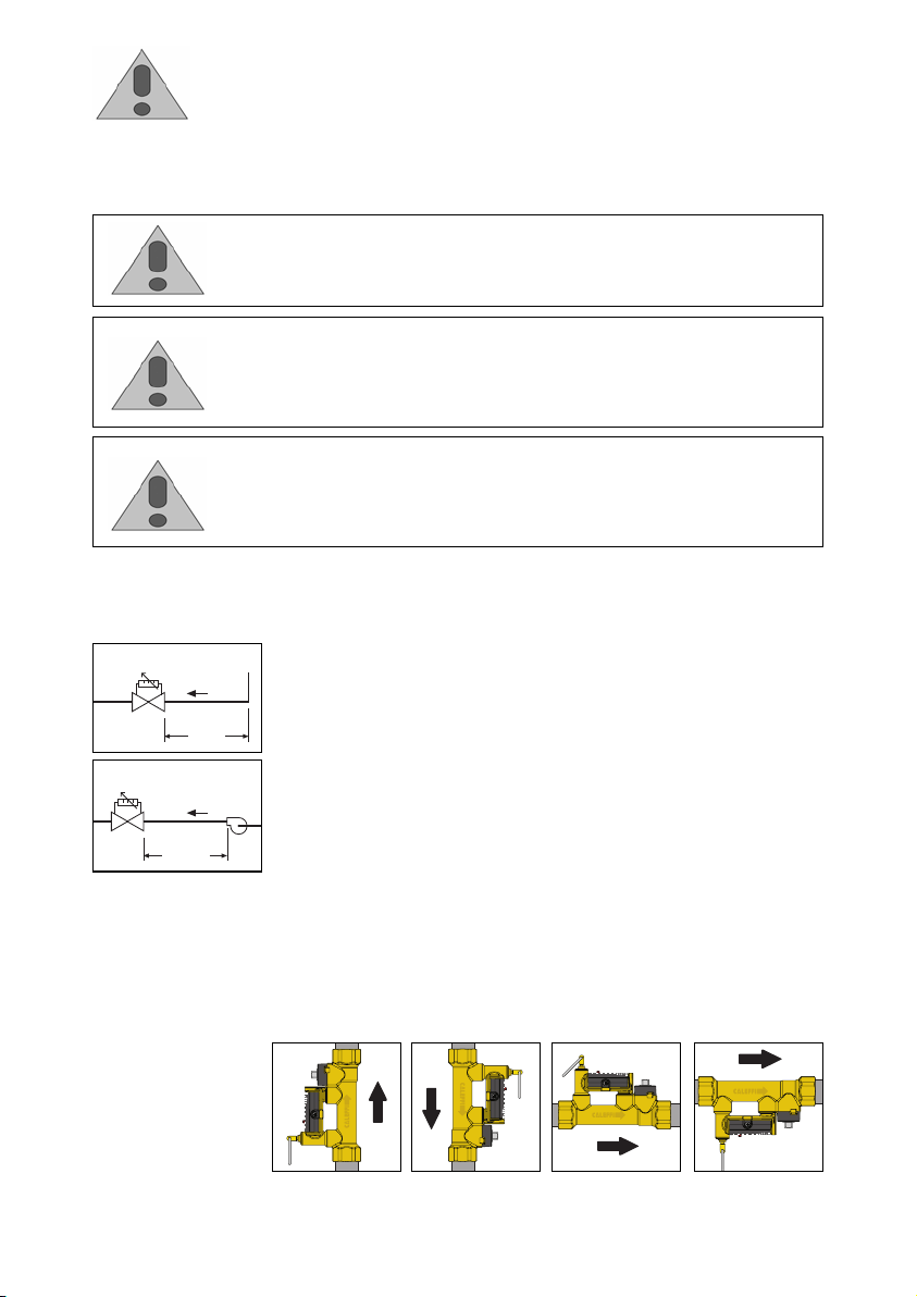
In order to ensure measuring accuracy, the balancing valves with flow
meter must be installed by keeping a straight section above them at
10D
least as long as five diameters, increased to at least ten diameters if
the nearest device upstream is a pump.
The valves must be installed so that:
- the direction of the flow agrees with that of the arrow on the
valve body.
- there is easy access to the flow meter valve, control stem and dial
with the calibration adjustment range.
The valves can be fitted on either vertical or horizontal pipes.
Page 3
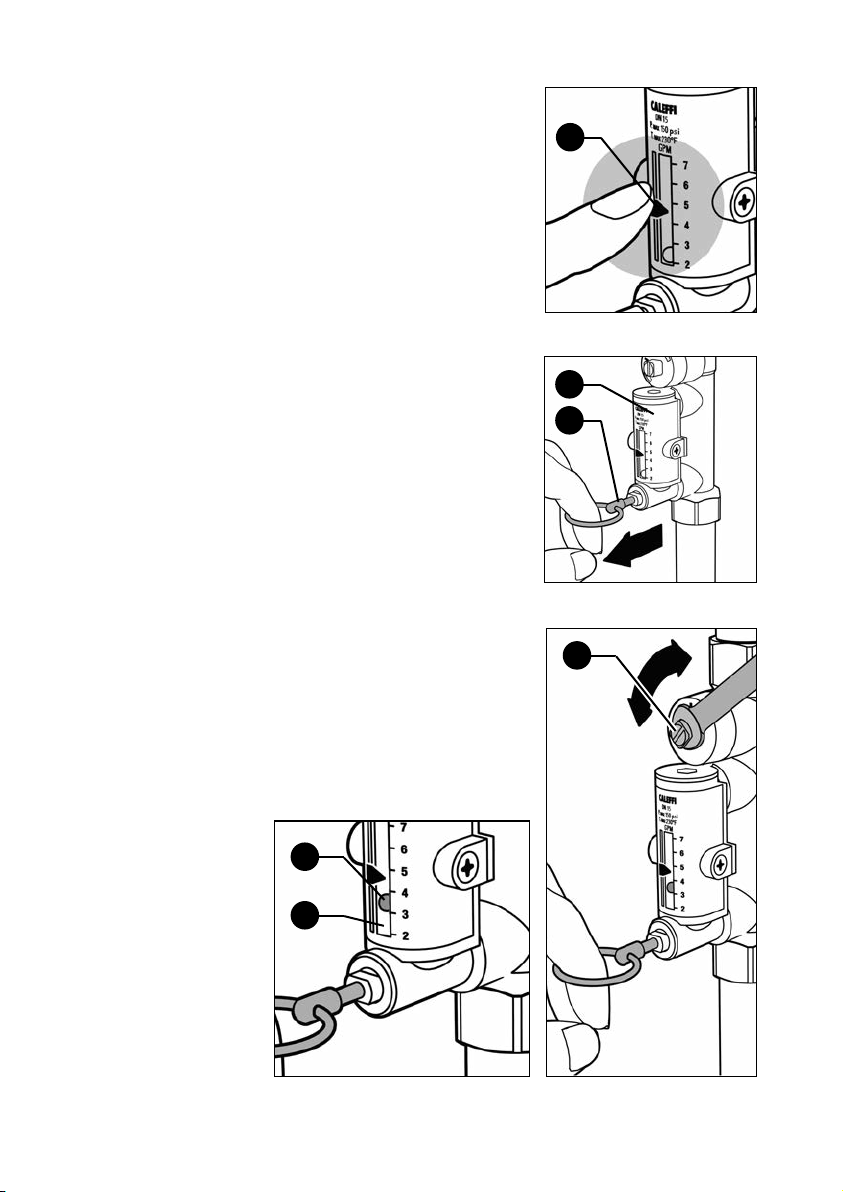
Flow rate
adjustment
The flow rate is adjusted by carrying
out the following operations:
A. With the aid of the indicator (1),
mark the reference flow rate on
which the valve is to be set.
B. Use the ring (2) to slowly open the
flow meter bypass valve that shuts
off the flow of medium in the flow
meter (3) under normal operating
conditions.
C. Keeping the flow meter bypass
valve open, apply a wrench (9 mm
for 1/2" to 1 1/4" sizes; 12 mm for
1 1/2" and 2" sizes) to the balancing
valve control stem (4) to slowly
adjust the flow rate, which is
indicated by a metal ball (5) that
runs inside a transparent cylinder
(6) alongside which there is a
graduated scale in GPM.
1
3
2
4
5
6
Page 4
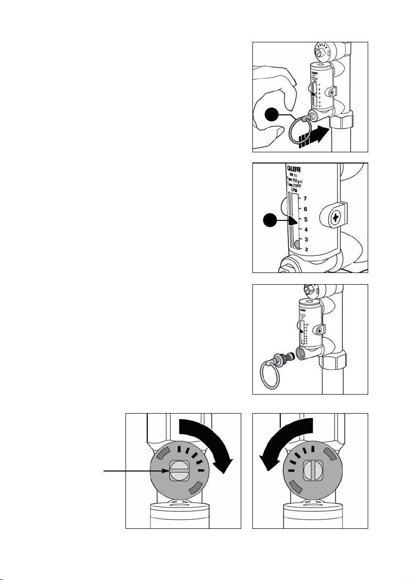
D. After completing the
balancing, release the ring (2)
of the flow meter bypass
valve, which will automatically
go back into the closed
position.
E. On completing the
adjustment, the indicator (1)
can be used to keep the
setting in memory, in case
checks need to be made
over time.
F. A replacement flow meter
bypass valve stem with
operating ring is available in
the event it is damaged and
inoperable.
Order code F19346. See
page 6 for replacement
instructions.
2
1
Complete
closing/opening
of valve
Balancing valve
control stem
Complete opening of valveComplete closing of valve
Page 5

Hydraulic
100
0.1
1
0.2
0.3
0.5
200
500
∆p (psi)
G
(l/h) (
gpm
)
10
2
3
5
20
0.1
1
0.2
0.3
0.5
(psi) (bar) (feet of head)
10
2
3
5
20
0.01
0.1
0.02
0.03
0.05
1.0
0.2
0.3
0.5
4
0.4 0.4
4
0.04
0.4
1000
2000
5000
10000
20000
1
0.2
0.5
2
5
10
2
0
50100
2
00
5
0
1/2”
3/4”
1”
1 1/4”
1 1/2”
2”
46.20
23.10
11.55
9.24
6.93
4.62
2.31
1.16
0.924
0.693
0.462
0.231
characteristics
at 100% open
Code Connection Flow rate (GPM) Cv
132432A 1/2” NPT 1/2 – 1 3/4 1.0
132552A 3/4” NPT 2.0 – 7.0 6.3
132662A 1” NPT 3.0 – 10.0 8.3
132772A 1 1/4” NPT 5.0 – 19.0 15.2
132882A 1 1/2” NPT 8.0 – 32.0 32.3
132992A 2” NPT 12.0 – 50.0 53.7
Page 6
CALEFFI
Procedure for
installation and
insulation
assembly
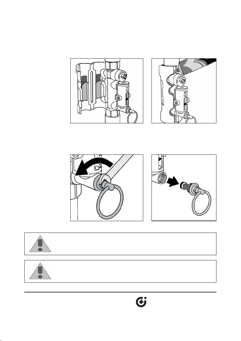
Procedure for
replacing bypass
valve stem with
operating ring
1.
Remove the protective strip from the adhesive
insulation shells.
2.
If the balancing valve with flow meter is used with chilled water, spread a
thin layer of sealant on the edge of the insulation and wait until the solvent
evaporates (10 minutes approx.) and then re-close it.
1.
Remove bypass valve assembly with an 8 mm wrench.
2.
Install replacement bypass valve assembly, code F19346, using locktight
to seal the threads.
surface. Re-close the
CAUTION: If the balancing valve valve is not installed, commissioned and
maintained properly, according to the instructions contained in this
manual, it may not operate correctly and may endanger the user.
CAUTION: Make sure that all the connecting pipework is water tight.
Caleffi North America, Inc.
3883 West Milwaukee Road
Milwaukee, WI 53208
T: 414.238.2360 F: 414.238.2366
 Loading...