

Page 1
www.caleffi.com
HydroCal™ Hydraulic, Air, and Dirt Separator
38712.03
© Copyright 2013 Caleffi
549 Series
Installation, commissioning and servicing instructions
Function
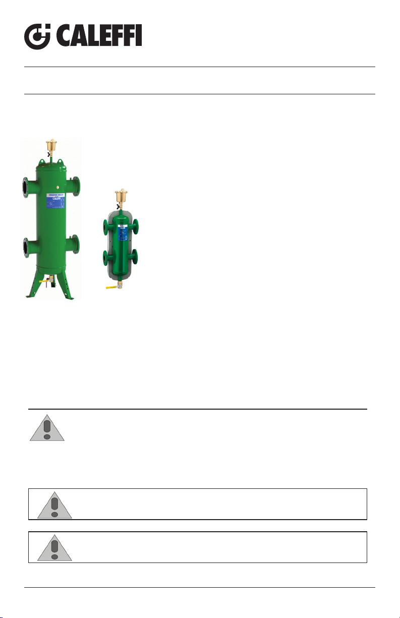
The Caleffi HydroCal™ combination hydraulic, air, and dirt
separator is a device that, incorporates high performance air
and dirt removal functionality into the hydro separation function
which makes the primary and secondary circuits connected to
it hydraulically independent, and can be used on hot or chilled
water systems. The HydroCal™ features a proven stainless steel
internal element that combines to continuously and automatically
eliminate air micro-bubbles with the simultaneous removal of dirt
particles as tiny as 5 microns. The air discharge capacity is very
high, with the capability of automatically removing all the air
present in the system down to the micro-bubble level. The 3 in 1
high performance functionality of the HydroCal™ saves system
installation and maintenance costs as there is no need to include
separate air and dirt separators.
Product range
549 series HydroCal™ hydraulic, air, and dirt separator in steel with flanged
connections, drain and insulation connections 2” – 4” ANSI
NA549 series HydroCal™ hydraulic, air, and dirt separator in steel with flanged
connections, drain and insulation, ASME and CRN connections 2” – 4” ANSI
NA549 series HydroCal™ hydraulic, air, and dirt separator in steel with flanged
connections and drain, ASME and CRN connections 6” – 12” ANSI
SAFETY INSTRUCTION
instructions. When used, the safety alert symbol means ATTENTION! BECOME ALERT! YOUR
SAFETY IS INVOLVED! FAILURE TO FOLLOW THESE INSTRUCTIONS MAY RESULT IN
A SAFETY HAZARD.
This safety alert symbol will be used in this manual to draw attention to safety related
CAUTION: All work must be performed by qualified personnel trained in the
proper application, installation, and maintenance of systems in accordance
with all applicable codes and ordinances.
CAUTION: If the HydroCal™ is not installed, commissioned and maintained
properly, according to the instructions contained in this manual, it may not
operate correctly and may endanger the user.
1
Page 2

CAUTION: Make sure that all the connecting pipework is water tight.
CAUTION: When making the water connections, make sure that the
hydronic separator connecting pipework is not mechanically over-stressed.
Over time this could cause breakages, with consequent water losses which,
in turn, could cause harm to property and/or people.
CAUTION: Water temperatures higher than 100°F (38°C) can be dangerous.
During the installation, commissioning and maintenance of the hydronic
separator, take the necessary precautions to ensure that such temperatures
do not endanger people.
Leave this manual for the user.
Technical specifications
Materials
Separator body: epoxy resin painted steel body
Air vent body & shut-off and drain valve body: brass
Internal element: stainless steel
Air vent seal: VITON
Air vent float: stainless steel
Performance
Suitable fluids: water and non-hazardous glycol solutions up to 50%
Max. operating pressure: 150 psi (10 bar)
Temperature range: - with insulation 32–220°F (0 – 105°C)
- without insulation 32–250°F (0 – 120°C)
Particle separation capacity: to 5 μm
Connections
Flanged: 2”–12” ANSI B16.5 150 CLASS RF
Drain valve: - connections 2”– 6”: 1–1/4” NPT female
- connection 8”– 12”: 2” NPT female
Agency Approval
Series NA549 is designed and built in accordance with Section VIII, Division
1 of the ASME Boiler and Pressure Vessel Code and tagged and registered
with the National Board of Boiler and Pressure Vessel Inspector, and CRN
registered.
Technical
Inner part
Material: rigid closed cell expanded polyurethane foam
Thickness: 2 3/8” (60 mm)
Density: 3 lb/ft3 (45 kg/m3)
Conductivity (ISO 2581): 0.16 BTU·in/hr·ft2·°F (0.023 W/(m·K)
Temperature range: 32–220°F
(0–105°C)
Outer part
Material: Embossed aluminium
Thickness: 7-mil (0.70 mm)
Fire resistance (DIN 4102): Class 1
Head covers
Heat formed material: PS
specifications
of insulation
2
Page 3
Hydraulic
characteristics
The HydroCal™ should be sized according to the maximum flow rate value
foreseen at the inlet. The selected value is the primary circuit flow rate, or
secondary circuit flow rate, whichever is largest.
Size
gallons
gpm
3
m
/h
l/s
2” 1/2” 3” 4” 6” 8” 10” 12”
4 4 8 8 23.2 95 175 255
37 62 94 148 376 625 1030 1650
8.5 18 14 22 86 142 234 422
2.3 4.0 6.0 9.3 23.7 40 65 104
Installation
The installation of HydroCal™ should only be carried out by qualified
personnel in accordance with current legislation.
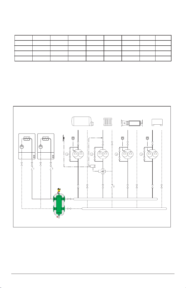
The HydroCal™ is installed between the primary and secondary circuits,
always in a vertical position.
3
Page 4
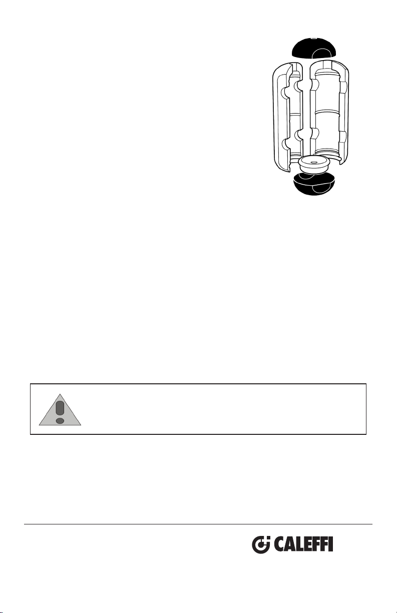
Procedure for installation and insulation assembly
(only for 2” to 4” sizes)
1. Remove the two black head covers at the ends.
2. Open the two side sections and the lower cap.
3. Install the separator in the system.
4. For cooling applications, consider using a silicon caulk
or sealant by spreading a thin layer of sealant over
surfaces A and B.
Wait for the solvent to evaporate (approx. 10 minutes).
Note that once the sealant dries it may be difficult to
remove the insulation shell in the future without
destroying portions of the insulation.
5. Reassemble the two side sections, fitting the lower cap
into one of the two sections and then connecting the other.
6.
Finish the assembly with the adhesive tape provided in the box.
7. Complete with the two black head covers.
8. Fit the automatic air vent and the drain valve.
CAUTION:
Periodically inspect for signs of corrosion or leakage. If corrosion or
leakage is note, the vent must be replaced. Failure to follow these
instructions could result in property damage and/or personal injury.
Service Instructions
There is no service required for the HydroCal™ Hydraulic, Air, and Dirt Separator.
Corrosion or leakage can cause damage or injury.
Caleffi North America, Inc.
3883 W. Milwaukee Road
Milwaukee, WI 53208
T: 414.238.2360 F: 414.238.2366
 Loading...