

Page 1
01166/10 NA
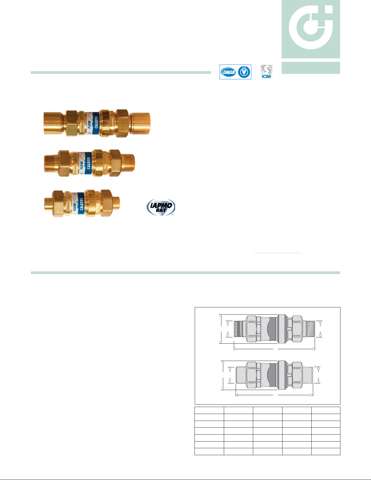
FLOWCAL™ Compact automatic flow
balancing valve
127 series
Function
The FLOWCAL™ automatic flow balancing valve maintains a fixed
flow rate within varying system differential pressure ranges.
The design incorporates an exclusive flow cartridge, made of an
anti-scale, low noise polymer and a compact low-lead brass valve
body for use in cooling, heating and domestic water systems.
Product range
127 series FLOWCAL compact automatic flow balancing valve, with polymer cartridge, NPT or Sweat Union sizes 1/2”, 3/4”, 1"
CALEFFI
Technical specifications
Materials
Body: low-lead brass (<0.25% Lead content)
Flow cartridge: anti -scale polymer
Spring: stainless steel
Seals: EPDM
Performance
Medium: water, glycol solutions
Max. percentage of glycol: 50%
Max. working pressure: 232 psi (16 bar)
Working temperature range: 32-212°F (0-100°C)
Connections: 1/2”, 3/4”and 1” NPT or Sweat Union
Flow Rate: 16 fixed flow rate settings
ranging from 0.5 - 10 GPM
Flow Accuracy: ±10%
Differential Pressure Control Ranges: 2-14, 2-32, 4-34, 5-35 psid
Agency Approval:
Lead Plumbing Law Compliance: (0.25% Max. weighted
average lead content)
Lead Plumbing Law Certified by IAPMO R&T
ACCREDITED
ISO 9001 No. 0003
ISO 9001 FM 21654
Dimensions
A
1/2" NPT
1/2" Sweat
3/4" NPT
3/4" Sweat
1" NPT
1" Sweat
B
5 13/16"
4 1/4"
5"
4 13/16"
5 5/8"
6"
C
1 9/16"
1 9/16"
1 9/16"
1 9/16"
1 9/16"
1 9/16"
Weight (lb)
1.0
0.8
1.0
0.8
1.2
1.0
Code
127341AF...
127349AF...
127351AF...
127359AF...
127361AF...
127369AF...
A
B
A
C
A
B
A
C
Page 2
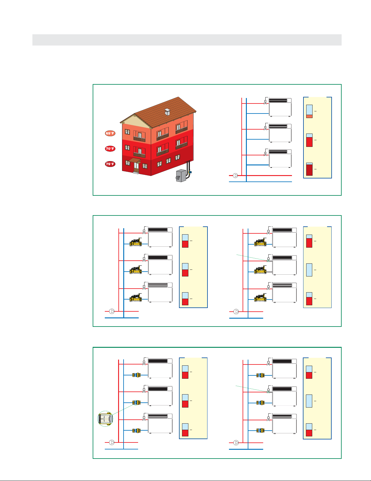
Modern heating and air-conditioning systems have to guarantee a high level of thermal comfort with a low energy consumption. This means
supplying the system terminals with the correct design flow rates, to produce balanced hydraulic circuits.
Circuit balancing
Circuits balanced with FLOWCAL
FLOWCAL balances
the hydraulic circuit
by automatically
controlling the design
flow rate to each
emitter.
Even with some
circuits partially
closed by the
control valves, the
flow rates in the open
circuits remain
constant at the
nominal value. The
system always
provides the greatest
comfort and the
highest energy
savings.
FULL LOAD
Control
valve
(closed)
PARTIAL LOAD
FLOWCAL
FLOWCAL
100 %
100 %
100 %
Flow rate
100 %
0 %
100 %
Flow rate
Circuits balanced with manual valves
Traditionally, hydraulic
circuits are balanced
using manual
calibration valves.
With these static-type
devices, such circuits
are difficult to balance
perfectly and have
operating limitations
in case of partial
closure by means of
the control valves.
The flow rate in the
open circuits does
not remain constant
at the nominal value.
FULL LOAD PARTIAL LOAD
Manual valve
Control
valve
(closed)
Manual valve
100 %
100 %
100 %
Flow rate
140 %
0 %
120 %
Flow rate
Unbalanced circuits
In case of an
unbalanced circuit,
the hydraulic
imbalance between
emitters creates areas
with temperatures
which are not
uniform, and, as
a consequence,
problems with thermal
comfort and higher
energy consumption.
50 %
140 %
180 %
Flow rate
Page 3

Function
The FLOWCAL automatic flow balancing valve guarantees a constant flow rate when the upstream/downstream pressure differential varies.
It is therefore necessary to refer to the Δp vs. flow rate diagram and to a basic diagram illustrating the operation methods and the relevant
variable effects.
Operating principle
The FLOWCAL flow cartridge is composed of a cylinder, a spring-loaded piston, and a combination of fixed and variable geometric orifices
through which the fluid flows. These variable orifice sizes increase or decrease by the piston movement, contingent on the system’s fluid thrust. A
specially calibrated spring counteracts this movement to regulate the amount of fluid which may pass through the valve orifices, maintaining a
balanced system. FLOWCAL valves are high performance automatic flow balancing valves which control selected flow rates within a very tight
tolerance (approximately 10%) and offer a wide range of operation.
*These values are for this example. The same logic applies to the other Differential Pressure Control Ranges: 2 -14, 4 - 34, and 5 -35 psid.
In this case, the spring-loaded regulating
piston remains in equilibrium without
compressing the spring and gives the fluid
the maximum free flow area. When below
the differential pressure control range the
piston acts as a fixed orifice and thus the
flow rate through the FLOWCAL depends
only on the differential pressure.
If the differential pressure is within the control
range, the spring-loaded piston is positioned
to give the fluid a free flow area permiting
regular flow at the nominal rate for which the
FLOWCAL
is set up.
In this case, the spring-loaded piston fully
compresses a spring and leaves only the
fixed orifice for the fluid to pass through.
The flow rate through the
FLOWCAL
depends only on the differential pressure.
FLUID THRUST
FLUID THRUST
FLUID THRUST
2 psi 32 psiDIFFERENTIAL
PRESSURE
FLOW RATE
G
0
Range Δp 2–32 psi
where G0 = nominal flow rate
DIFFERENTIAL
PRESSURE
FLOW RATE
G
0
Control range
Initial Δp
Final Δp
2 psi 32 psi
Range Δp 2–32 psi
where G0 = nominal flow rate
FLOW RATE
DIFFERENTIAL
PRESSURE
G
0
2 psi 32 psi
FLOWCALTMAutomatic Flow Balancing Valves
Below the differential pressure control range (< 2 psid)*
Within the differential pressure control range (2 - 32 psid)*
Above the differential pressure control range (> 32 psid)*
Page 4

Construction details
Polymer flow cartridge
The flow rate cartridge is made of an anti-scale polymer,
specially engineered for use in cooling, heating and domestic
water systems, to prevent mineral buildup.
Its mechanical behavior is excellent in a wide range of
working temperatures, it features high resistance to the
abrasion caused by continuous fluid flow, it is insensitive to
the deposit of scale and is fully compatible with glycols and
additives used in circuits.
Exclusive design
With its exclusive design, the flow cartridge is able to
accurately control the flow rate in a wide range of operating
pressures. A special internal chamber acts as a damper for
the vibrations triggered by the fluid flow, allowing low noise
operating conditions to the device.
For these reasons it can be used in systems both on zone
branch circuits and directly at the terminals.
Size the hydronic system with FLOWCAL automatic balancing
valves as follows:
1. ΔP
MAXCIRCUIT
Determine the pressure head loss for the zone circuit with
the greatest pressure drop (flow resistance). This is true for
any hydronic system with supply and return headers.
As an example, this would be circuit #8 for the 2-pipe direct
return system with circuits having identical resistance,
illustrated to the right, as it is farthest from the pump. If,
however, all circuits are not identical, choose the circuit with
the greatest pressure drop.
2. ΔP
MINFLOWCAL
Add the minimum differential operating pressure
(2, 4, or 5 psid) required for the FLOWCAL model selected
for the circuit with the greatest pressure drop.
3. PUMP HEAD = ΔP
MAXCIRCUIT + ΔPMINFLOWCAL
Pump Sizing using FLOWCAL
TM
Flow rate table
7654321 8
Control valve
FLOWCAL
TM
Code
127341AF ● ● ●
127341AF ● ● ●
127341AF ● ● ●
127341AF ● ● ●
127341AF ● ● ●
127341AF ● ● ●
0.50; 0.75; 1.00; 1.50; 2.50; 3.00; 3.50; 4.00; 4.50; 5.00; 6.00; 7.00; 8.00; 9.00; 10.00
0.50; 0.75; 1.00; 1.50; 2.50; 3.00; 3.50; 4.00; 4.50; 5.00; 6.00; 7.00; 8.00; 9.00; 10.00
0.50; 0.75; 1.00; 1.50; 2.50; 3.00; 3.50; 4.00; 4.50; 5.00; 6.00; 7.00; 8.00; 9.00; 10.00
0.50; 0.75; 1.00; 1.50; 2.50; 3.00; 3.50; 4.00; 4.50; 5.00; 6.00; 7.00; 8.00; 9.00; 10.00
0.50; 0.75; 1.00; 1.50; 2.50; 3.00; 3.50; 4.00; 4.50; 5.00; 6.00; 7.00; 8.00; 9.00; 10.00
0.50; 0.75; 1.00; 1.50; 2.50; 3.00; 3.50; 4.00; 4.50; 5.00; 6.00; 7.00; 8.00; 9.00; 10.00
Size
Δp range (psid)
Flow rates (gpm)
2–14
2–32
4–34
5–35
1/2” NPT
1/2” Sweat
3/4” NPT
3/4” Sweat
1” NPT
1” Sweat
CARTRIDGE LOCKING NUT
CARTRIDGE
BODY
This is equal to the minimum working Δp of the FLOWCAL cartridge: 2, 4 or 5 psi (13, 27 or 31 kPa).
Minimum differential pressure required
Page 5

Code Description
127341AF ... 1/2" NPT Male
127349AF ... 1/2" Sweat
127351AF ... 3/4" NPT Male
127359AF ... 3/4" Sweat
127361AF ... 1" NPT Male
127369AF ... 1" Sweat
Select desired flow rate to complete full part number.
No restrictions.
Differential Pressure Differential Pressure
Last 3 digits Control Ranges Last 3 digits Control Ranges
GPM ... (psid) GPM ... (psid)
1/2 G50
2 - 14
4 4G0
3/4 G75 4.5 4G5 2 - 32
1 1G0 5 5G0
1.5 1G5 6 6G0
2 2G0
2 - 32
7 7G0 4 - 34
2.5 2G5 8 8G0
3 3G0 9 9G0
5 - 35
3.5 3G5 10 10G
Order Code Numbering for FLOWCALTM127 series
Applications of FLOWCALTM()
For use in line with various types of heat emitters: radiators,
convectors, fan convectors, thermal strips, etc.
To guarantee the design flow rates (with open or closed valve)
to the various zones of a system.
To ensure constant flow rates (in any valve position) in
circuits with traditional temperature control.
T.A .
T.A .
T.A .
To ensure constant flow rates to each emitter.
Installation of FLOWCAL
In air-conditioning systems,
FLOWCAL
devices should preferably be installed on the circuit return pipe.
Some typical installation examples are given below.
Page 6

Applications of FLOWCALTM()
To create heat exchanger flow balancing by-passes
To control the amount of delivered water and balance the
various circuits in irrigation systems.
To limit the hot water flow rate delivered in systems with
instantaneous production or limited capacity.
To balance sanitary water distribution circuits.
SPECIFICATION SUMMARIES
127 series
Compact automatic flow balancing valve with polymer flow cartridge FLOWCAL™. Connections 1/2”, 3/4”, 1” union sweat or
NPT. Brass body. Anti-scale polymer cartridge. Stainless steel spring. EPDM seals. Water and up to 50% maximum glycol
solutions. Maximum working pressure 232 psi (16 bar). Working temperature range 32
–
212°F (0–100°C). Δp range 2–35 psi.
Range of available flow rates for all connection sizes 1/2 - 10 gpm. Accuracy ±10%.
We reserve the right to change our products and their relevant technical data, contained in this publication, at any time and without prior notice.
Caleffi North America, Inc.
3883 West Milwaukee Road / Milwaukee, WI 53208
Tel: 414.238.2360 / Fax: 414.238.2366 / www.caleffi.us
© Copyright 2010 Caleffi
CALEFFI
 Loading...