

Page 1
Calef S.p.A.
S.R. 229 no. 25 - 28010 Fontaneto d’Agogna - Italy
www.calef.com
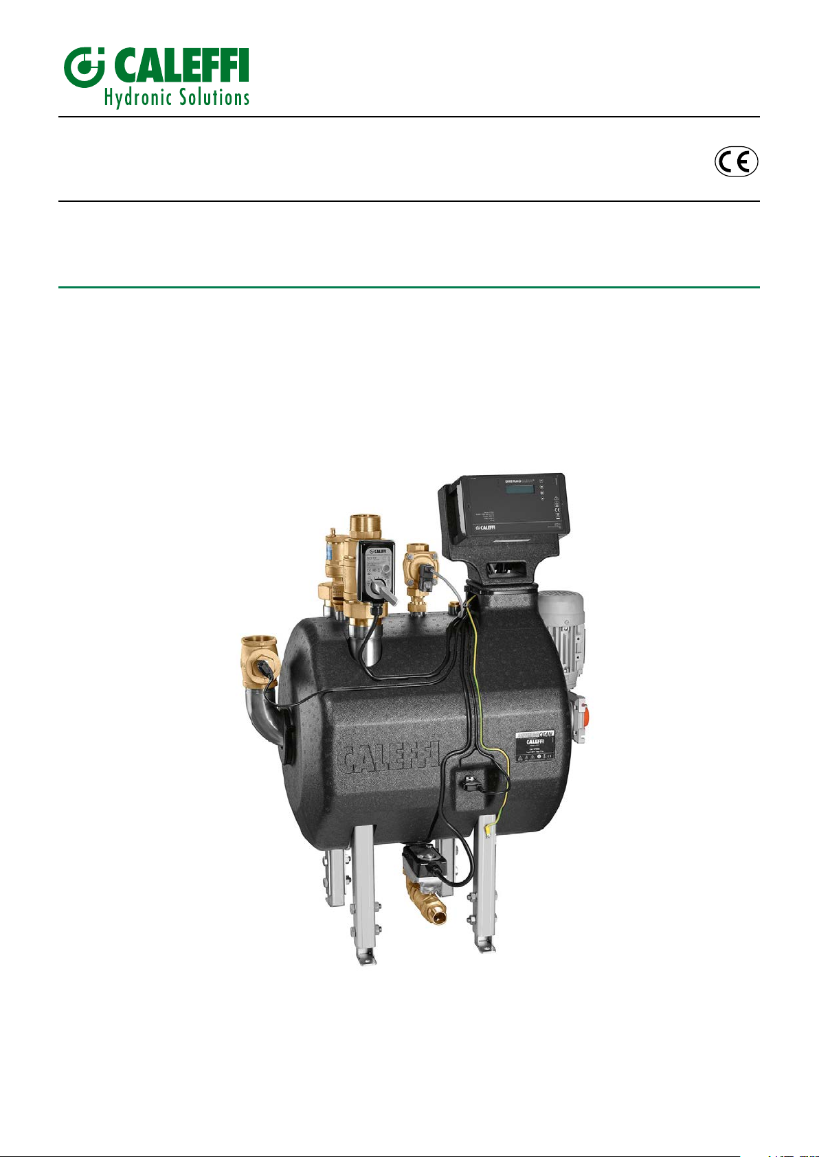
DIRTMAGCLEAN
Self-cleaning magnetic dirt separator strainer
H0006359
© Copyright 2018 Caleffi
Code 579000
USE AND MAINTENANCE MANUAL
ORIGINAL
INSTRUCTIONS
DATE: 01/07/2018
REVISION: 00
Page 2

TABLE OF CONTENTS
Contents
1 Introduction 3
1.1 Purpose of the manual 3
1.2 Requirements for use 3
1.3 Symbols 3
1.4 Denitions 4
2 General information 4
3 Characteristic components 5
3.1 Package composition 5
3.2 Technical features of the device and valves 5
3.3 Regulator and actuator technical features 5
3.4 Sizing 6
General description of the operation 6
4
4.1 Operating principle 6
4.2 Filtration 7
4.3 Filtering elements cleaning 7
4.4 Circuit lling and operating conditions reset 8
Overall dimensions 9
5
6 Adhesive labels location 9
6.1 Electrical connections label 10
7 Intended use 10
8
Packaging, handling and transport 11
8.1 Instructions for unpacking 11
8.2 Storage 11
8.3 Reception 11
8.4 Handling 12
8.5 Disposal of packaging 12
9 Installation 12
9.1 Hydraulic installation 13
9.2 Installation in by-pass 13
9.3 Device reset 15
9.4 Electrical installation 15
9.5 Cables wiring and positioning 15
9.6 Example of electrical connection for circulator management 16
9.7 Example of electrical connection with two parallel strainers 16
9.8 Battery installation 16
10 Regulator description and operation 17
10.1 Front panel 17
10.2 Display 17
10.3 Regulator operation 17
11 Commissioning 19
11.1 Filling and hydraulic test under pressure 19
11.2 First start-up 19
12 Maintenance 19
13 Important notice for correct disposal of the product 21
14 Malfunctions - troubleshooting 21
15 Spare parts 22
16
Risks, protections, warnings and cautions 22
Manufacturer's liability and warranty 23
17
18 Table of Interventions 24
2
Page 3
1 Introduction
Dear Installer,
Thank you for choosing the self-cleaning magnetic dirt separator strainer, which we hope will always satisfy you; this product has been manufactured
in compliance with the most stringent safety regulations in force.
To ensure the safety of personnel, the self-cleaning magnetic dirt separator strainer referred to in this use and maintenance manual must be handled,
installed, used, maintained and dismantled/eliminated by carefully following the instructions provided in this use and maintenance manual in compliance
with the applicable law.
This manual is intended for operators and specialized personnel in order to allow correct use of the product. Please consider this information essential
as a practical guideline to installation, use and maintenance of the strainer.
This manual is an integral part of the self-cleaning magnetic dirt separator strainer and has been entirely prepared by the manufacturer in order to
provide the necessary information to all those who are authorized to interact with it.
This publication describes the status of the product at the time of publication and can in no way reect the future and non-standard product. The
contents of this manual have been checked for their correctness and compliance with the equipment described. However, it is not possible to
guarantee that there are no differences.
1.1 Purpose of the manual
The user manual is intended to provide all the information necessary for the installer to be able to manage the strainer in the most autonomous and
safe way possible:
• correct awareness of personnel to safety issues;
• dirt separator strainer, packaged and unpacked, handling in safety conditions;
• correct installation of the dirt separator strainer;
• in-depth knowledge of its operation and its limits;
• carry out maintenance operations correctly and safely;
This manual is to be considered as an integral part of the self-cleaning magnetic dirt separator strainer:
• it must be kept for the whole life of the strainer
• It must accompany the strainer in case of transfer to another owner.
To facilitate consultation and better detail the topics, the manual is divided into chapters.
Before carrying out any installation, use or maintenance operation, it is absolutely essential to read this manual carefully in all its parts.
The information not included, which concerns the assembly, disassembly, extraordinary maintenance, repair and installation of any safety accessories,
devices and equipment or electronic parts programming, can only be carried out by authorized personnel or by the authorized technical service, in
compliance with the recommendations provided by the manufacturer and the current health and safety regulations.
For any data not contained in this manual it is recommended to contact the manufacturer.
The dirt separator strainer is equipped with an electrical system that complies with the 2014/30/EU; 2014/35/EU directives.
A copy of the EU Declaration of Conformity is an integral part of the use and maintenance manual or on request to the manufacturer.
The construction complies with the provisions of the Machinery Directive 2006/42/EC.
1.2 Requirements for use
All maintenance and operating cycle operations must be carried out by qualied, trained, authorized personnel in suitable psycho-physical conditions.
The maintenance technician must wear appropriate personal protective equipment: protective gloves for mechanical maintenance; gloves, clothing and
tools with a suitable degree of insulation for electrical maintenance.
Important! It is absolutely forbidden to remove or tamper with the accident prevention labels; if this is found, the manufacturer declines all responsibility
for any damage resulting from such removal.
1.3 Symbols
The symbols shown are used to draw the reader's attention to points of particular interest for the safety of the person or the strainer or to identify
particular operating conditions.
CAUTION, a general danger situation for
the safety of the person and/or for the
integrity of the machine
CAUTION, a general electrical danger
situation for the safety of the person and/
or for the integrity of the machine
Operating instructions
Read the instructions before use
Danger of re Mandatory safety footwear
Danger, hot surface Mandatory eye protection
Danger of ice formation Mandatory use of protective gloves
3
Page 4

1.4 Denitions
DANGER ZONE
Any zone inside and/or near the self-cleaning magnetic dirt separator strainer, within which the presence of an exposed person constitutes a risk for
the safety and health of said person (Annex I, art. 1.1.1 Directive 2006/42/EC).
EXPOSED PERSON
Any person who is completely or partially in a danger zone (Annex I, art. 1.1.1 Directive 2006/42/EC).
INSTALLER / INTEGRATOR / MAINTAINANCE OPERATOR
Person in charge of installing and/or performing maintenance on the self-cleaning magnetic dirt separator strainer according to the intended use.
INSTALLER / INTEGRATOR / MAINTENANCE OPERATOR QUALIFICATION
Minimum level of skills that personnel must have.
SELF-CLEANING MAGNETIC DIRT SEPARATOR STRAINER
Purpose of this manual.
INTENDED USE
Use of the self-cleaning magnetic dirt separator strainer according to the information provided in this document.
RESIDUAL RISK
Danger that it was not possible to eliminate or sufciently reduce through the design, against which the protections are not (or are not totally) effective;
in this manual, information on its existence is given along with instructions and warnings to allow it to be overcome (see, respectively, 5.4 and 6.5.1 of
the European standards EN ISO 12100-1 and EN ISO 121000-2).
MANUFACTURER
Manufacturer of the self-cleaning magnetic dirt separator strainer.
EMPLOYER
The company including its chief executive ofcer, who is responsible for the installation of the self-cleaning magnetic dirt separator strainer that is
covered by this manual.
USER
Recipient to use the self-cleaning magnetic dirt separator strainer.
OPERATOR
Person in charge of installing, operating, regulating and cleaning the machine.
QUALIFIED TECHNICIAN
Specialized person, specially trained by Calef S.p.A. and authorized to carry out extraordinary maintenance or repairs requiring a particular knowledge
of the machine, of its operation, of the safety devices and their methods of intervention.
The operator and the qualied technician are obliged to read and understand the contents of this manual, which must be preserved intact and be an
integral part of the strainer.
2 General information
Manufacturer’s company name and address
CALEFFI S.p.A. S.R. 229, N. 25 – I – 28010 FONTANETO D’AGOGNA (NO)
General safety warnings
The dirt separator strainer has the exclusive function of ltering water and glycol solutions (max 50%). All liquids other than water and
glycol are excluded: therefore radioactive acids, explosives and contaminants are explicitly excluded. A different use excludes the
manufacturer from any responsibility for damage caused to the dirt separator strainer, property and persons. The designer, or installer,
is responsible to check the product compatibility with additives or substances dissolved in water.
Before carrying out the installation, check that the safety and operational standards of the strainer are complied with, in accordance
with the regulations in force.
Prior to the installation phase, check that the support surface is suitable to support the weight of the full strainer.
All operations described in this manual and in particular lifting, positioning, installation and connection to energy sources, within the
limits described and specied in this manual, must be performed by qualied and authorized personnel, in full compliance with the
instructions reported below and in compliance with the laws in force in the country of installation. Any operation not described in the
manual is to be considered prohibited and can not be carried out, except by authorized technical service personnel.
Tel. +39 03228491 - info@calef.com - www.calef.com
Designation of the machine
DIRTMAGCLEAN
Art. 579000
ATTENTION: disconnect the strainer from the electrical mains using a suitable disconnector device, before any intervention.
Check the electric supply cables carefully and periodically; cables that are not intact or are worn out are a serious danger. Always be
vigilant and attentive, about the operation in progress if you decide to carry out an intervention on the strainer.
In case of incorrect operation, immediately interrupt the use and call the qualied technicians. If further information is required regarding
the points mentioned above, contact exclusively and in advance the Authorized Technical Service or the Manufacturer. It is forbidden
to tamper with the devices and circuits that govern its safety. It is forbidden to modify the strainer without the manufacturer’s written
authorization.
4
Page 5
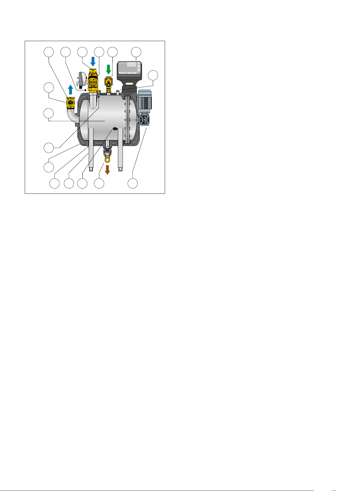
3 Characteristic components
10
11 6 7 4 2
15
13
1
14
9812 5
1. Filtering unit with magnets
2. Digital regulator
3. Single-phase electric motor (M1)
4. Solenoid valve (V2) with built-in check valve
5. Drain valve (V3)
6. Ball inlet valve (V1)
7. Automatic air vent valve with combined strainer
8. Insulation
9. Adjustable support feet
10. Clapet check valve
11. Vacuum breaker valve
12. Temperature and pressure probe S1
13. Temperature and pressure probe S2
14. Additive pouring cap
15. 1/2” connection with pressure gauge cap
16. 1/2” connection with cap for additional drain valve
3.1 Package content
• Filtering unit with magnets
• Installation and commissioning manual
• Programming manual
• Movement platform
• Packaging carton
3.2 Technical features of the device and
valves
Materials
Body-pipes and support feet: stainless steel AISI 10088-2
(AISI 304)
Internal filtering elements: polyester
Inlet and drain valves
Body: brass EN 12165 CW617N
Ball: brass EN 12165 CW617N, chrome plated
Ball seal: PTFE with EPDM O-Ring
Control stem seal: double EPDM O-Rings
Union seal: EPDM O-Ring
Loading and cleaning valve
Body: brass EN 12165 CW617N
Seals: EPDM
Circuit return valve with clapet retainer
Body: brass EN 12165 CW617N
Seals: EPDM
316
Performance
Medium: water, glycol solutions
Maximum percentage of glycol: 50%
Maximum working pressure: 10 bar
Working temperature range: 5–85°C
Hydraulic characteristics: Kv = 45 m3/h
Water content: 50 l
Strainer mesh size Ø: 30 µm
Particle separation rating: down to 2 μm
DHW inlet minimum dynamic pressure for 3 bar wash
Motor noise: < 60 dB
Volume of water drained during washing:
about 100 litres with p = 3 bar
Connections
- in circuit inlet: 2” M with captive nut
- in circuit outlet: 2” F
- filled for cleaning: 1” F
- drain: 1” M with captive nut
- additive pouring cap: 1” F
3.3 Technical features
regulator and actuators
Regulator
Material
Housing: PA6G30 anti-UV Grey RAL 7024
Electric supply: 230 V (ac) 50/60 Hz
Power consumption: 225 VA in cleaning phase and 5W in stand by
Insulation class: I
Protection class: IP 42
Ambient temperature: 5–50°C
Contact rating:
- IN1 relay: clean contact
- 3-point G.OUT control: Max 5 (2) A, 250 V
- ALARM relays: Max 1A, 48 V
- OUT1 relay: Max 1A, 48 V
Fuses: 2A (motor) and 315mA (actuators)
Battery: R2032 225 mAh - life approximately 1 year
(for only keeping date and time in the absence of network)
Inlet and drain valves
Synchronous motor
Electric supply: 230 V (ac)
Power consumption: 6 VA
Protection class: IP 65
Operating time: 60 s
Loading and cleaning valve
Solenoid type - normally closed (NC)
Electric supply: 230 V (ac)
Power consumption: 6 VA
Protection class: IP 65
Single-phase electric motor
Electric supply: 230 V (ac)
Power consumption: 0.18 kW
Protection class: IP 55
Ambient temperature range:
- Operation: 5 - 50°C EN 60721-3-3 Cl. 3K3 max. humidity 85%
- Transportation:
-30–70°C EN 60721-3-2 Cl. 2K3 max. humidity 95%
- Storage: -20–70°C EN 60721-3-1 Cl. 1K3 max. humidity 95%
Conforms to Directives: CE
Insulation
Material: EPP
Average thickness: 50 mm
Density: 45 kg/m3
Operating temperature range: 5–85°C
Thermal conductivity: 0.037 W/(m•K) at 10°C
5
Page 6
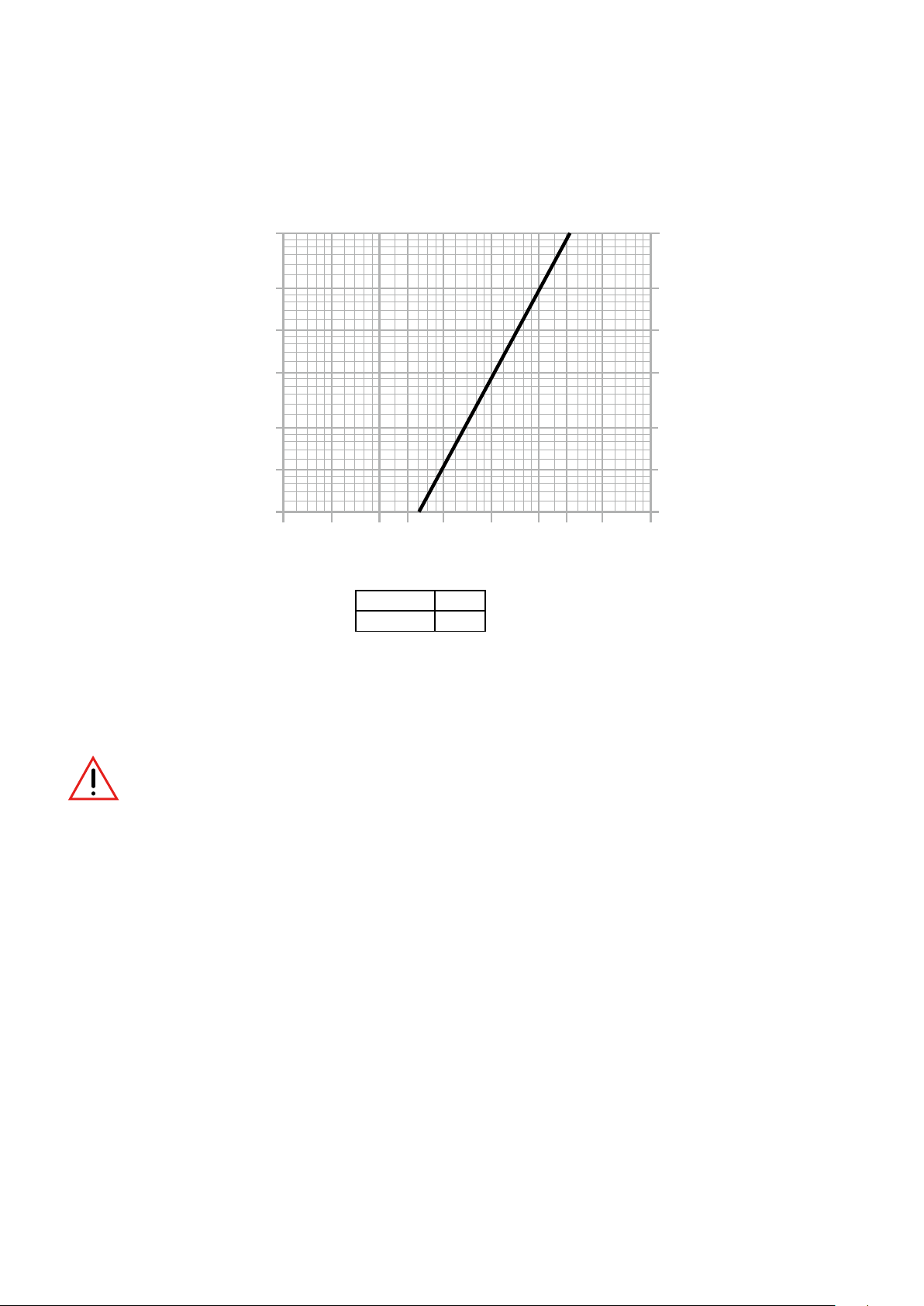
3.4 Sizing
The sizing of the dirt separator strainer must be performed considering the following values:
Maximum recommended flow rate: 20 m3/h
Hydraulic characteristics
Δp(mm w.g.) Δp(kPa)
5000
50
2000
1000
500
200
100
50
0.5
2
3
1
5
10
20
30
50
20
10
5
2
1
0,5
100
G(m3/h)
Connections
Kv
(m3/h)
4 General description of the operation
The dirt separator strainer consists of a series of elements that make it possible to obtain a product capable of carrying out a constant and continuous
filtration of the system water and automatic cleaning.
2"
45
The device is used only in central heating systems to remove dirt and impurities from the circuit progressively and completely.
The device must not be used by persons (including children) with impaired physical, sensory or mental capabilities, or lack of experience
and knowledge, unless they are instructed.
Any use of the device other than its intended use is prohibited.
4.1 Operating principle
This device flushes the system circuit medium by direct action through the direct action of passing through the specific filtering elements appropriately
arranged inside the body. The specific filtering mesh allows the removal of impurities that are deposited on the external surface of the strainers.
The very selective mesh filters particles with a diameter of 30 μm at the first passage and separates dirt particles up to 2 μm. At the same time, ferrous
particles are separated out by the magnets on the surface of the filter element.
Automatic cleaning of the filtering elements takes place mechanically by means of washing with pressurised mains water while the filtering elements
rotate.
In all its functional phases - operation, cleaning,filling and draining - the device is controlled by a special digital regulator, which can also be managed
remotely using a BMS system running MODBUS-RTU protocol.
This device operates according to different operating steps:
- filtration/ normal operation
- filtering elements cleaning
- circuit filling and operating conditions reset
The digital regulator manages the opening status of the inlet and load/drain valves, together with the strainers rotation motor during the cleaning. The
cleaning phase is automatically activated according to a preset pressure drop value or in a programmed way.
Depending on the type of system, the device can be combined with others for parallel operation.
6
Page 7

4.2 Filtration
During normal operation, the medium coming from the system enters in the strainer body through the motorised ball valve V1. The medium is forced
to pass through the filtration discs, then it is conveyed into the central part until it comes out of the device through the clapet check valve.
Inlet from the system
H0004833
4
Cale S.p.A.
S.R. 229 no. 25
28010 Fontaneto d’Agogna
Italy
System return
Clapet check valve
V1
Supply: 230V (ac) ±10%
IP 42
P
MAX: 10 bar (1 MPa)
579 series
Power: xxx VA
T
MAX: 90°C
MIN: 5°C
T
T
ROOM: 5-50 °C
4.3 Filtering elements cleaning
It can be activated manually, by time or automatically by controlling the medium pressure drop between internal pressure and pressure detected after
the filtering elements. The choice of the type of operation is carried out by the regulator. During the first cleaning phase (emptying) the inlet ball valve V1
closes while the clapet check valve prevents the system backflow. Once the inlet valve V1 is completely closed, the drain valve V3 is opened, located
in the lower part of the device. When the vacuum breaker valve, present in the upper part of the strainer body, is opened it allows the progressive
draining of the tank, causing part of the dirt to come out.
Vacuum breaker valve
H0004833
4
Cale S.p.A.
S.R. 229 no. 25
28010 Fontaneto d’Agogna
Italy
Clapet check valve
V1
Supply: 230V (ac) ±10%
IP 42
579 series
Power: xxx VA
P
MAX
: 10 bar (1 MPa)
: 90°C
MAX
T
T
MIN: 5°C
ROOM: 5-50 °C
T
V3
7
Page 8
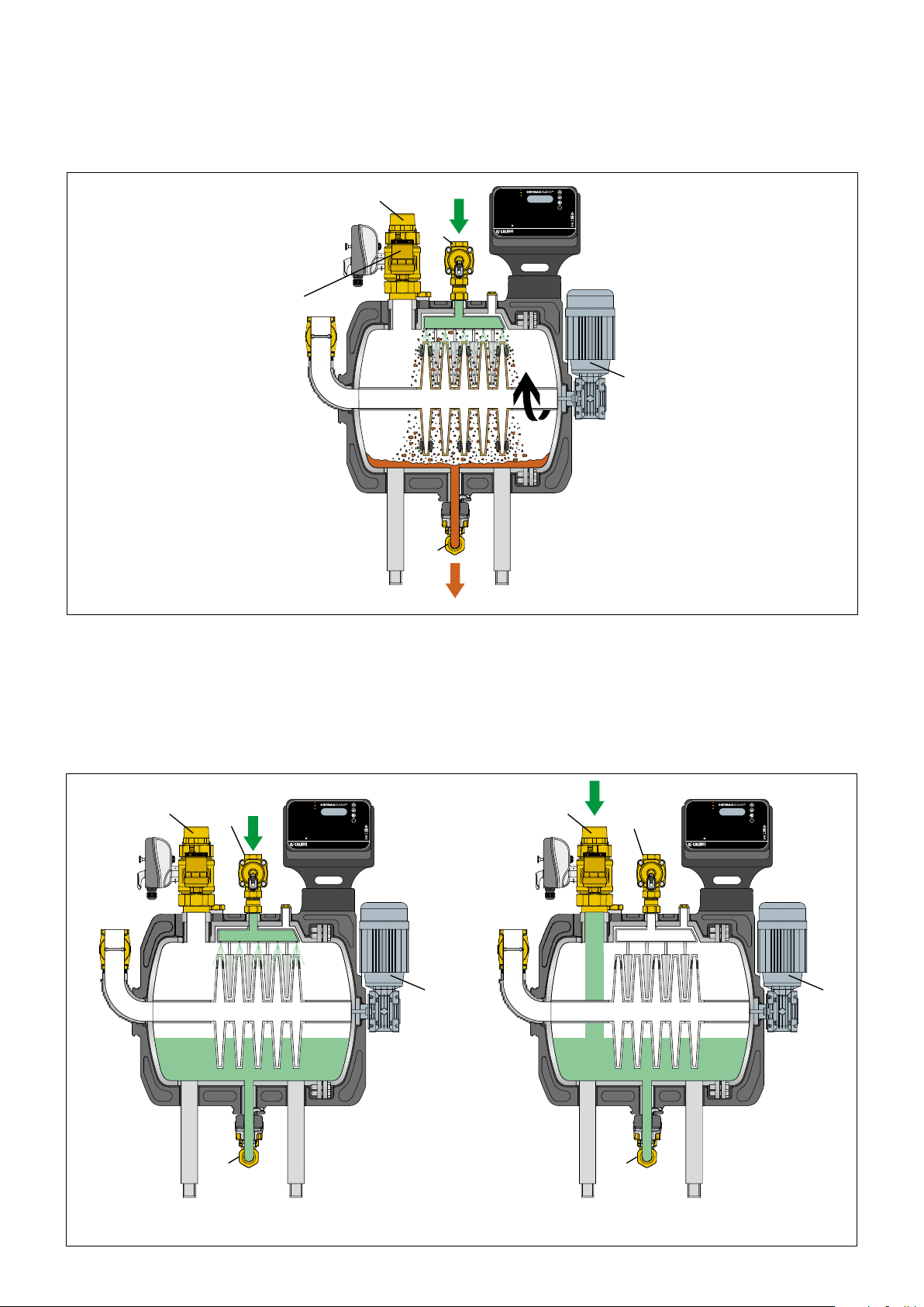
During the second cleaning phase (mechanical cleaning with water injection), the two-way solenoid valve V2 (equipped with check valve) is opened
injecting water from the water mains. In order to perform an effective cleaning, a minimum dynamic pressure of 3 bar must be guaranteed during
washing and the installation of an anti-backflow system is mandatory to protect the aqueduct network (apply according to local regulations in force).
At the same time the shaft on which the filtering discs are clamped is rotated by means of the motor M1, in order to allow the fixed brushes to clean
their surface and to clean the magnets.
Air vent valve
V1
V3
V2
Supply: 230V (ac) ±10%
P
MAX: 10 bar (1 MPa)
IP 42
H0004833
579 series
Power: xxx VA
MAX: 90°C
T
T
MIN: 5°C
ROOM: 5-50 °C
T
4
Cale S.p.A.
S.R. 229 no. 25
28010 Fontaneto d’Agogna
Italy
M1
4.4 Circuit filling and operating conditions restoring
At the end of the cleaning phase the initial conditions are restored, in order to continue with the normal filtration. The drain valve V3 is closed and
the rotation of the motor M1 is stopped. The strainer can be filled in two ways: with mains water through the solenoid valve V2 or using the system
circuit through the valve V1. This second option is preferable when the water in the heating circuit is treated and contains additives. The filling action
is gradual until the pressure detected in the system is reached. During this phase the air vent valve starts to expel the air in the tank and allows
optimal filling.
V1
V2
Supply: 230V (ac) ±10%
IP 42
H0004833
579 series
Power: xxx VA
P
MAX: 10 bar (1 MPa)
MAX: 90°C
T
T
MIN: 5°C
ROOM: 5-50 °C
T
4
Cale S.p.A.
S.R. 229 no. 25
28010 Fontaneto d’Agogna
Italy
V1
V2
Supply: 230V (ac) ±10%
IP 42
P
MAX: 10 bar (1 MPa)
579 series
Power: xxx VA
MAX: 90°C
T
T
MIN: 5°C
ROOM: 5-50 °C
T
M1
H0004833
4
Cale S.p.A.
S.R. 229 no. 25
28010 Fontaneto d’Agogna
Italy
M1
V3
V3
Filling with system waterFilling with mains water
87
Page 9

5 Overall dimensions
528
256
978 - 1028 - 1078 - 1128
450 -500-550-600
360
6 Adhesive labels location
IMPORTANT: The product is already
congured according to the specications
indicated in the technical documentation.
IS CASE OF NEED, or for technical information related to the
operation, please contact the external after-sales serviceat the
number 0322 849301
906 - 956 - 1006 - 1056
650 - 700 - 750 - 800
125
250
125
260
550
139196 326
758
450 -500-550-600
460
202,5
94,5-144,5-194,5-244,5
9
Page 10

6.1 Electrical connections label
H0004960
1
2
S1
+
1
2
S2
-
230 V
50 Hz
μ
1 A
max
48 V
˜
OPEN
CLOSE
COM.
N
L
N L
M1
˜
N L
V2
V1 G. OUT IN1V3
M1
CLOSE
COM.
OPEN
CLOSE
serie 638serie 638
COM.
OPEN
ALARM
OUT1
+
BUS
F6 = 2A - 250 Vac
F7 = 315 mA - 250 Vac
M1 V1 V3
230 V
˜
50 Hz
S1
S2V2
AB
SCH
7 Intended use
The device is intended for use exclusively in heating systems containing water or water+glycol solutions up to a concentration of 50%. The device
can be used in systems with maximum medium temperature of 85°C and maximum pressure of 10 bar. The minimum operating temperature of the
medium is 5°C. In case of application with condensation phenomena, the installer must provide an adequate and safe system to prevent or dispose
of the condensation build-up in order to prevent damage to persons or property. The maximum ambient temperature is 50°C. The minimum ambient
temperature during operation is 5°C, in the absence of condensation. The device must be assembled on the boiler return, with a suitably sized and
calibrated bypass. The drawing below shows the operator's stop zones for the machine operation and control. Provide a passage area around the
strainer of at least 50 cm and, at the rear, an area for extraordinary maintenance (strainer disassembling) of at least 100 cm:
50 cm
50 cm
AREA TO LEAVE FREE
FOR EXTRAORDINARY
MAINTENANCE
50 cm
100 cm
WARNING: do not stand up, lean or sit on the machine.
ATTENTION: if the connection pipes are not properly insulated they could result in high temperature and cause burns and scalds. Provide
a correct and safe insulation of all hot surfaces.
Page 11

8 Packaging, handling, transport
1120
800
600
The strainer is fixed on a wooden pallet. An external carton with cover protects the strainer in order to prevent damage that could occur during
handling. The packaging is single-use and must be disposed of according to the indications provided for by the regulations in force.
Before any movement, make sure that the elements used for transport (trolleys, bridge cranes, nylon straps, ropes, etc.) are in perfect working order
and can withstand loads of not less than 100 kg.
The strainer must be lifted respecting the indications provided.
Move body and hands away when the strainer is lowered. Failure to follow these instructions could result in serious injury.
For no reason the personnel is authorized to pass under the load or near it, not even the signalman who will provide assistance to the movements.
Do not tilt or overturn the pallet.
The manufacturer declines any responsibility related to this phase that must be carried out by personnel
specialized on handling industrial machinery (wheelers, boaters), equipped with the necessary personal
protective equipment (overalls, safety shoes, work gloves, hard hat, goggles).
The movement must take place slowly, under suitable lighting conditions, with suitable free space in the
installation area.
Important! It is forbidden to handle the strainer with methods other than those indicated in the following document. Failure to comply with
these conditions could cause serious injury to the user
8.1 Instructions for unpacking
First open the cover and then the cardboard side, then remove the pallet with the strainer.
8.2 Storage
Do not overturn or tilt the package.
Multiple packages can not be stacked. Do not place any weight on top of the packaging.
8.3 Reception
The packaging consists of appropriate material and prepared by expert personnel: the devices therefore are sent with all their parts and in perfect
condition.
However, to check the quality of the transport services and in case the packaging is insured, follow the instructions below:
• upon receipt, before unpacking, check if the box is damaged, in which case collect the goods accepting them conditionally, producing photographic
evidence of the apparent damage.
• check that the components of the device have not been damaged during transport, in which case notify within 8 days of receipt, producing
photographic evidence.
11
Page 12

8.4 Handling
It is advisable to move the strainer using mechanical devices (lift truck, crane, bridge crane, etc.) of adequate capacity.
For lifting it is advisable to use standard belts, positioned as indicated in the illustrations
aside, taking care to keep them always tensioned so that they do not slip and taking
care to keep the strainer parallel to the ground.
The device must be handled only if completely empty. The presence of liquids may
cause them to leak or alter the center of gravity during handling. These conditions can
also cause serious damage to property or persons.
The device has an indicative empty weight of 50 kg: handling must be carried out
according to safety regulations.
During the handling and temporary storage outside the wooden platform prepare all the
necessary precautions to prevent the device from falling or overturning.
8.5 Disposal of packaging
Follow the regulations in force for the disposal of the various components of the packaging.
9 Installation
When connecting water pipes, make sure that threaded connections are not overstressed mechanically. Over time this could result in breakage, with
water leaks causing damage and/or injury. Check the hydraulic seal of all connection fittings.
Water temperatures above 50°C can cause serious scalding. When installing, commissioning and servicing the device, take the
necessary precautions so that these temperatures will not be hazardous for people.
The device coupling with other system components must be made while taking the operational characteristics of both units into
consideration. An incorrect coupling could compromise the operation of the device and/or system.
The strainer must be installed in a closed and dry place, protected from atmospheric agents. It must be positioned in a stable manner. The floor must
be solid and well levelled. The installer must take care of the positioning of the strainer, maintaining adequate space around it to guarantee accessibility
to every point of the system.
During installation it is possible to adjust the height of the device from the ground, by appropriately
repositioning the fixing screws in the holes of the new desired height. This operation must be
carried out lifting the device with suitable lifting devices to guarantee the safety levels necessary
to prevent accidents and damage. Be careful to the correct fastening of the leg screws and
tighten the nuts with a torque of 25 Nm.
The device must be installed in a horizontal position, firmly fastened to the floor by means of
suitable fastening systems inserted in the holes (Ø 12 mm) set up at the base of the legs.
The dirt separator strainer can not be installed in prohibited areas according to the ATEX regulation (Directive 2014/34).
Comply with the law regulations regarding the relative evaluation.
Failure to comply with the installation and start-up conditions could also cause a high level of risk for the user.
CAUTION:
• avoid exposing the device and cables to direct sunlight or sources of heat.
• to minimize residual vibrations caused by the flow of water it is necessary to maintain flow values that are suitable for use and fixed
pipes without any discontinuity or obstacles within the flow.
• check that the fastening clips of the temperature and pressure sensors are correctly positioned. Do not remove them for any reason.
• do not open the drain valve manually.
• check that the insulation is well positioned and correctly closed.
• do not remove the sensor and sensor clips
• do not disassemble or loosen the nuts and seals during operation.
12
Page 13

9.1 Hydraulic installation
Installation in by-pass with dedicated pump
NOTE The strainer regulator does not directly control the activation of the circulation pump.
9.2 Installation in by-pass
3
m
Provide suitable safety devices to be installed on the system near the appliance to prevent any possible risk due to overpressure. Suitable
safety devices must be installed in order to prevent exceeding the maximum pressure declared for the device or pipes, in compliance
with current regulations.
Pipes with suitable mechanical characteristics must be used for the installation: use pipes made of metal material adequately fixed to
support structures in order to not mechanically overload the connections and the legs of the device and in way to guarantee a fixed
position of the pipes, also during installation and commissioning.
The device must be installed according to the diagrams given in this manual. It must compulsorily be installed on the return circuit, to
collect the impurities present in the circuit, especially during the system activation phase (closing the by-pass valve at the same time),
before they can reach the boiler.
The drain system must be operated in way that it does not prevent normal operation, avoiding counter pressure and must not endanger
people or things. It must be conveyed into a dedicated pipe or collecting tank. Check compliance with local standards and regulations
regarding the filtration water draining into the sewage system, depending on the substances present in the water and in the sludge
collected and the temperature of the medium.
13
Page 14

It is possible to adjust the drain in the most appropriate direction rotating the motorised ball drain valve and its fitting after loosening the cap. Take
care not to bend-stress the valve. This operation must be carried out before commissioning, with a completely empty and pressure-free device.
The device drains the liquid collected that can be at high temperatures (> 50°C), depending on the characteristics of the system in which
it is installed: use appropriate precautions to comply with local regulations in force and concerning the water drain.
To prevent contamination of the drinking water network and to avoid backflow phenomena, install a hydraulic backflow preventer and a
suitable strainer upstream of the strainer cleaning solenoid valve.
Limit as much as possible the length of the domestic pipes used for cleaning: use water hammer arrester or other devices to suppress
instantaneous overpressure that may occur during operation.
The domestic water inlet line for strainer washing may be subject to thermal overpressure: install suitable safety relief valves or expansion
vessels.
The domestic hot water inlet line may be subject to freezing risk. Provide suitable insulation or systems to avoid ice formation.
To allow an easier installation it is possible to invert the position of the inlet valve V1 with the automatic air vent having the same 2 1/2” thread. This
operation must be carried out during installation, with a pressure-free and completely empty strainer.
14
Page 15

9.3 Device reset
H0004960
The "Reset device" function allows to interrupt all the functions in progress and to set to the initial condition. This function cancels the alarms and
anomalies present, if any.
1. Press and hold "OK" until the configuration menu is displayed.
2. Press "OK" under "Forcing".
3. Using the arrow up, move to "1.8 Reset device" and press "OK" (see the instruction sheet H0005275).
4. Using the arrows, change "OFF" to "ON" and press "OK".
5. Wait for the device to reset.
9.4 Electrical installation
The electrical connections must comply with the technical specifications in this manual, strictly adhering to the attached wiring diagrams.
CAUTION: Risk of electric shock. Cut off the electric supply before carrying out any work. Failure in following these instructions may
result in injury of persons or damage to property. The installer must provide an electrical line equipped with an automatic differential
release system upstream of the machine main switch and a suitable earthing system that meets all the requirements of the accidents
prevention standards.
The electrical panel is inserted inside a box of PA6G30 (polyamide reinforced with 30% glass fibre) IP 42. Connect the 230V electric supply to the
appropriate connectors L - N and make the connection to earth, using the cable gland provided. Probes and actuators are factory wired and therefore
do not require connection.
Comply with the instructions on the label inside the device and the enclosed diagrams: the wiring must be carried out by qualified technical personnel,
respecting the regulations in force.
The wiring must be carried out properly by qualified technical personnel and in compliance with the directives and standards in force
in the country of installation.
For the electrical supply connections of the device and the low voltage elements for power supply, it is necessary to comply with the
applicable regulations in force using cables with cross section and insulation suitable for the place of installation and suitable pipes or
protection pipes.
9.5 Cables wiring and positioning
To access inside the controller, use a flat screwdriver, insert it into the side slots and gently
pry it to open it. Connect the 230 V electric supply to the appropriate connectors L - N
and make the connection to earth, using the cable gland fitted. Cable H05VV-F 3G1.5 or
with superior features according to current legislation. Cable gland PG11 external diameter:
5-9 mm. Probes and actuators are factory wired and therefore do not require connection.
The electric supply cable insulation must comply with the standards applicable to the
environment (or room) in which the device is installed
N
230 V
50 Hz
L
N L
M1
˜
M1
F6 = 2A - 250 Vac
F7 = 315 mA - 250 Vac
Before commissioning, check the correctness of the earthing and of the
interruption and protection devices.
When installing the electric supply cable and other cables, do not touch the
electronic board and its components. Avoid the formation of chips and strands
and minimize the cables length to prevent them from damaging the board.
1
2
S1
+
1
2
S2
-
N L
V2
OPEN
CLOSE
COM.
V1 G. OUT IN1V3
CLOSE
COM.
OPEN
CLOSE
serie 638serie 638
COM.
OPEN
μ
1 A
ALARM
max
48 V
OUT1
˜
+
BUS
M1 V1 V3
230 V
˜
50 Hz
S1
S2V2
AB
SCH
IN1 input for contact with no voltage applied. When the contact is closed, the strainer cleaning is inhibited
OUT1 NO relay output The contact closes when the strainer is in the cleaning phase (max 48 V (ac), 1A)
ALARM NO relay output for alarm management (max 48 V (ac), 1A)
V3 electric supply output for inlet motorised ball valve V3 management
G. OUT electric supply outlet for cold water injection valve control on the drain 5 (2A), 250 V (ac) max
V1 electric supply relay output for ball motorised valve with input ball V1 management
V2 electric supply relay output for nozzle cleaning solenoid valve V2 management
M1 electric supply relay output for motor M1 management
L – N – T electric supply 230 V (ac) 50/60 Hz
BUS control Modbus RTU 485 interface
S1 digital input for pressure and temperature sensor S1
S2 digital input for pressure and temperature sensor S2
15
Page 16

9.6 Example of electrical connection for circulator management
BA
61
Control
system
A
L
N
230V ac
24Vac
B
OUT 1
Relay
24V
The circulators A (boiler circulator) and B (strainer service circulator) operate simultaneously. When the strainer is in the cleaning phase (OUT1 contact
closed), the 24V relay (to be inserted separately) removes electric supply from the pump B, stopping it until the end of cleaning.
9.7 Example of electrical connection with two parallel strainers
1 2
12345
IN1OUT1ALARM IN1OUT1ALARM
MAX10
23456
IMPORTANT! respect the polarities
1 2
When the strainer 1 is cleaned, the OUT1 contact closes, which being connected to the IN1 contact of the strainer 2, inhibits it simultaneous cleaning.
When the cleaning phase of strainer 1 is finished, it is possible to clean strainer 2 again. This configuration is applicable also in case of strainer 2
cleaning.
9.8 Battery installation
The presence of the battery allows the clock continuous updating. In case of low or missing battery, if there is no network, the device does not ensure
that the time and date are stored and therefore that the programmed cleaning operations are executed correctly.
NOTES:
• The button battery can be replaced with an optional battery code F0000692, type
ER AA Lithium-thionyl chloride 3.6V, to be connected to the connector on the board.
The battery life is approx. 10 years.
• The low battery warning ("B", flashing on the LCD display) is only reliable with the
battery correctly inserted.
16
Page 17

10 Regulator description and operation
The regulator is provided with several programs to clean the strainers. This can be performed according to a periodic program or it can be directly
controlled by an operator. Depending on the type and conditions of the circuit and the system maintenance management, the most suitable operating
modes can be selected, see the "controller operation” chapter.
10.1 - Front panel
1
2
3
✔
Series 579
Supply: 230V (ac) ±10%
Power: 225VA
AMB: 5–50°C
T
IP 42
www.cale.com
14
10.2 Display
The following information normally appears on the display:
Possible battery alarm
"B" or input "I"
Probe pressure S1
Day of the week
Probe temperature S1
5
6
7
8
Cale S.p.A.
S.R. 229 n° 25
28010 Fontaneto d’Agogna
1 Red LED: - xed (alarm notication with locked system)
- ashing (anomaly, system working)
H0004833
2 Yellow LED: cleaning signal or additive insertion in progress
3 Green LED: on (normal operation) and ashing during the rst cleaning
phase
4 LCD display
5 UP button
6 DOWN button
7 BACK button
8 Conrm/OK button
Italy
Time
Operating status
measured Δp
10.3 Regulator operation
For all information regarding the strainer digital regulator management, refer to the programming manual H0005275
NOTE. The regulator is easily adjustable, making the information reading easy in every direction
17
Page 18

Cleaning on instantaneous Dp
During normal operation, the device monitors the strainer clogging status, by measuring the differential pressure between inlet and outlet of the strainer
elements measured by the probes S1 and S2. When the difference exceeds a value set and modifiable by the user, an automatic strainer cleaning
cycle is immediately started.
Cleaning on delayed Dp
When the DP exceeds a predefined value (the same used to start the instantaneous cleaning), the cleaning is programmed to be performed but at a
time specified by the user.
Scheduled cleaning
It is possible to carry out a cleaning cycle on a specific day of the week, at a specific time or on several days of the same week. The device is cleaned
anyway even if the maximum set Dp value is not exceeded during operation. Cleaning can be scheduled for a particular day of the month, every two
months, every three months or every six months.
Initial cleaning
This function can be used after washing the system or anyway whenever an extraordinary cleaning of the system is necessary. Before starting this
function it is necessary to configure the duration. When the set Dp is reached, a washing cycle is immediately started. When the set number of
hours is reached, the first system cleaning function stops and the normal operating mode starts again, with the washes time management (e.g. once
a week) and/or based on the normal operation Dp value.
Manual forcing
It is possible to start the operating status through the forcing function, from the user interface or from remote (via bus). Once the required activation is
completed, the device returns to normal operation. Forcing allows, from the user interface, to individually start the cleaning, sleep, additive addition,
sensor control cycles.
Sleep
The sleep mode temporarily deactivates the device, setting it in a waiting status, with the valve V1 closing and without any control on the operation.
This status allows the device to be deactivated for a set time, for example when the system is shut down in the summer. At the end of the sleep
phase, the device resumes normal operation. The notifications for alarms remain active.
Use of additives
Additives can be added to the system medium activating the appropriate function. In this case the system is
set in stand by, after having carried out a forced cleaning cycle with a view to reducing as much as possible the
use of the water in the network, taking advantage of the tank emptying. During the waiting phase it is possible
to insert the necessary additives into the device using the 1” cap located in the upper part of the strainer, see
the characteristic components drawing. Carefully check the cap watertight closing, in order to prevent leakage
or flooding.
Additives must be in liquid form and must be added carefully and slowly to prevent accidental spills
Check the compatibility between the type of additives used and the dirt separator strainer materials. Any
incompatibility can cause serious damage to the machine, to people and property. Avoid contact with
skin and eyes. Avoid inhalation, use personal protective equipment. Do not disperse in the environment.
Refer to the safety data sheet and the technical documentation of the product. It is advisable to insert
max 40l of additives. If necessary, the function can be executed several times.
Sensors check
The regulator periodically checks the correct operation of the sensors. This procedure can be carried out manually through the item on the regulator
menu.
Drain temperature limitation
The system is provided with a function to cool the water drain when the temperature is higher
than a given value (that can be changed). During cleaning, if the system detects that the medium
temperature is higher than the admissible temperature, the activation of a specific G. OUT relay is
activated, which remains active until the drain ends.
The activation of the G. OUT relay must be used by the user to provide a system for reducing the drain water temperature of the device,
for example through a valve that injects cold water into the drain. Check the local regulations in force.
Faults
Abnormal operating conditions do not stop the operation of the device but are indicated on the display and allow to prevent more serious
problems (red LED flashing on the front panel). For more details about the alarms, refer to the "programming manual" code H0005275.
Alarms
In the event of serious problems that compromise the system safety conditions, it is set into a locked state. The relative status is shown
on the display (red fixed LED on the front panel), in addition the "ALARM" relay sets to the closed position. The latter may possibly be
connected to an optical and/or acoustic alarm system. For more details on the symbols related to the alarms, refer to the "programming
manual" code H0005275.
18
Page 19

11 Commissioning
Commissioning must be carried out according to the regulations in force by qualified personnel.
Check that the cold water supply pressures are within the operating limits of the device.
Check that the temperature of the hot drain water has a value complying with the regulations in force.
NOTE. To ensure the strainer correct operation, check that the air vent cap is sufficiently loose (1/2 turn from
completely closed).
Attention: the device performs a check during the filling phase from V2 at the end of the wash and
if the drain cocks is left closed, an alarm is generated. The device checks the correct opening of the
air vent to avoid injecting air into the system after each cleaning with filling from the domestic line.
For all information regarding the strainer digital regulator management, refer to the programming manual H0005275
At the first start-up, a careful analysis must be carried out to check that there are no leaks and the assembly is correct: the filling must be carried out
gradually in order to allow the correct expulsion of air by the vent valve.
Once the seals have been checked, the device can be electrically supplied: once the system is electrically supplied, it performs a series of checking
operations before starting the filtering function. After providing electric supply or after a reset, the system closes the inlet and drain valve and opens
again the inlet valve after carrying out a filling operation: these steps allow to limit the amount of water in the system drained and return the system
to the correct operating conditions.
Check that the pressure in the domestic water mains is in the strainer operating range (minimum 3 bar) to guarantee an effective cleaning of the
filtering discs.
11.1 Filling and hydraulic test under pressure
Important! Do not supply electricity to the controller until it is indicated.
1. Check that the inlet valve is in the open position and if necessary move it manually until it reaches the complete valve opening.
2. Check that the drain valve is in the closed position and if necessary move it manually until it reaches the closed position.
3. Check that the controller is not electrically supplied.
4. Check that the air vent cap opens.
5. Slowly open the shut-off valve upstream of the device inlet and pressurize the system.
6. Wait for the device to fill.
7. Check for leaks: if leaks or seepage are found, close the shut-off valve upstream of the device and correct the anomalies found. Now it is possible
to wait until the qualified personnel arrive to make the electrical connections for the device electric supply.
8. With pressurised device, power the controller: if it was previously electrically supplied or if an alarm was present, perform a "Device reset".
9. After a few seconds the yellow light will turn on to indicate that the device is carrying out some operations (filling and internal checks).
10. Wait for the yellow light to go off: in the meantime it is still possible to access the internal device configuration menus to set the date and time
and the type of cleaning to be performed.
11.2 First start-up
When the filtering system is started up for the first time, the "initial cleaning" function can be activated in the regulator menu. This function can be used
to wash the system using the medium contained in the system. This avoids to drain large quantities of medium and avoids the need for complicated
venting operations. When the set differential is reached, a washing cycle is immediately started. The system stops the initial cleaning function when the
set time is reached or when the DP is lower than the set one. Depending on the type of installation it may be necessary to close the by-pass valve.
Check that the flow rates are compatible with the characteristics of the strainer and with other elements of the system
System stop procedure
Before turning off the regulator it is necessary to stop the flow of liquid to be filtered closing the system input motorised valve (V1). Turn
off the electric supply to the regulator and manually close the inlet valve (V1).
System prolonged closing
If the system is closed, remove the electric supply to the regulator, manually close the inlet valve (V1).
19 20
Page 20

12 Maintenance
Introduction
Never perform maintenance and control operations with wet body parts. Wear the accident prevention equipment provided for by the regulations in
force.
Inspection and maintenance must always be carried out with the strainer stopped and without pressure. All operations must be performed by skilled
personnel authorized by the manufacturer to avoid damage to the internal parts. Failure to comply with these rules relieves the manufacturer of causes
for damage to persons and property and causes the loss of the warranty for damage to internal parts.
CLEARLY INDICATE THAT THE STRAINER IS IN MAINTENANCE APPLYING AN APPROPRIATE INDICATIONN SIGN.
Periodic checks
It is recommended to perform a preventive check of the strainer working status to avoid irreparable damage. It is recommended to perform a check
at least every 12 months.
To check the correct operation of all the strainer components it is necessary to carry out some periodic checks such as:
- Alarms history check
Note down the alarms that have occurred since the last check and carry out an analysis of the possible causes that triggered them.
- Anomalies history check
Note down the anomalies that have occurred since the last check and make an analysis of the possible causes that triggered them.
- Check that there are no leaks from the device
Check that there are no leaks from the device and from the drain valve.
- Check the correct operation of the controller and of the device elements
After having shut-off the inlet and the drain, check the operation of the various parts by means of manual forcing.
Check the actuators and the motor and the sensors pressure reading.
- Cables visual check
Check that the electric supply cable and the other cables do not show signs of degradation of the insulating sheath (hardening/cuts or tears).
- Check the earthing
Perform a visual check of the earth cable and the device earthing quality according to the regulations in force.
Minimum frequency: yearly or according to current legislation if more frequent.
- Verification of protection devices and electrical part command
Check the protection circuit breakers installed upstream of the device. Check the electric supply cut-off devices.
Minimum frequency: yearly or according to current legislation if more frequent.
- Installation check
Check the solidity and validity of the installation. Check that there are no signs of corrosion on the legs of the device and on the fixing bolts to the
ground.
- General check
Perform a general visual check of the device.
- Automatic air vent strainer cleaning
To carry out the periodic cleaning of the strainer on the automatic air vent valve, check that the strainer
is not pressurized, access the strainer unscrewing the 2 1/2” cap using the appropriate key. Clean the
strainer washing it under running water. Refit the strainer checking the status of the O-ring and replace
it if necessary. Tighten the nut checking for leakage or seepage.
Extraordinary maintenance
Carrying out regular periodic checks, no other type of intervention is required for extraordinary maintenance except in cases of damage due to external
causes or incorrect installations.
Record every intervention carried out on the "INTERVENTION TABLE".
20
Page 21

13 Important notice for correct disposal of the product
It is essential that the disposal is carried out in compliance with the above and in full compliance with the relevant regulations in force
in the user's country.
Since different regulations to observe are in force in the individual countries, the prescriptions imposed by local laws and by the competent authorities
must be observed. Important! The strainer demolition must be carried out by specialized personnel.
Before starting the disassembly, it is necessary to create around the strainer a sufficiently large and orderly space in order to allow all
the movements without problems of further risks created by the environment.
The machine, in "out of service" conditions, must be positioned in an area accessible only to authorized personnel.
To disable the strainer, it is necessary to:
Switch off and empty the hydraulic system setting it in safe conditions and disconnecting the device from it. Deactivate the electrical system
disconnecting the cables from the line to the electrical panel and from the electrical panel to the machine.
The strainer components disposal must be carried out by specialized recovery centers.
At the end of its working life, the product must not be disposed of as urban waste. It must be taken to a special differentiated waste
collection centres set up by local authorities or to dealers providing this service. Disposing of an electric or electronic appliance
separately avoids possible negative consequences for the environment and health deriving from inappropriate disposal and enables
the constituent materials to be recovered to obtain significant savings in energy and resources. As a reminder of the need to dispose
of electric and electronic appliances separately, the product is marked with a crossed-out wheeled dustbin.
Disposal of batteries: please respect the environment. Do not throw batteries into household waste. Used batteries must be delivered
to the appropriate collection centres. We would like to remind you that only spent batteries can be thrown into the used battery
collection bins. If the battery is not completely down, measures must be taken to prevent a short circuit. The crossed-out wheeled bin
mark indicates the obligation to dispose of batteries separately
All verification and checking operations must be carried out by qualified, trained and equipped personnel.
14 Malfunctions - Troubleshooting
Malfunction Solution
Repeated cleaning cycles
Degree of filtration not consistent
The air vent valve leaks
Leakage of liquid from the cover closing flange
- quality of the liquid to be filtered
- the system capacity must comply with the minimum operating capacity
- the strainer must not work out of maximum capacity
- the working pressure must be at least 1.5 bar
- Dp set too low
- strainer discs wear status
- rear seal ring wear status
- Replace the valve. It is recommended to periodically clean the combined
strainer to avoid this malfunction. To disassemble the valve it is necessary
to turn off the system, cut-off the device, disconnect the electric supply and
make the replacement after having removed pressure (and in cold conditions)
- tighten the flange fastening bolts and replace the seal no. 16 (spare parts
section).
21
Page 22

15 Spare parts
Consult the drawing of the spare parts with the relative table where the code and description of the individual parts supplied as spare parts are
indicated
Ref. Description Code
1 Gearmotor x art. 579000 spare part F0000955
2 Actuator 230V-90° 2 way- "t" -cable l = 125 638052
3 Electrical spare part N.C.-Ø1"f.-V.230/50-60 H F0000952
4 Pressure sensor rsp 0-10 bar spare part F0000954
5 Controller x 579000 spare part F0000951
6 Vacuum breaker valve d.1/2” spare part F0000949
7 Tailpiece ø1 "xø1" with nut-Rit.DN20 spare part F0000950
8 Discal deaerator with cup 1/2" F 551004
9 Motorised ball valve Ø2 "2 way 230v 638092
10 Ball zone valve two-way 1” 647060
11 Clapet check valve d.2 "F spare part F0000953
12 O-ring 62 x 3 ep-perox 70° sh spare part R57314
13 Strainer cleaning brushes x 579 spare part F0000958
14 Series 579 ltering unit spare part F0000960
15 Shaft sealing unit 579 series spare part F0000959
16 Seal for 579 series ange spare part F0000956
17 Ø1/4” gas nozzle with o-ring spare part F0000957
16 Risks, protections, warnings and cautions
General safety
In order to guarantee the health and safety of exposed persons, the strainer is equipped with the following safety devices: ACTIVE SAFETY DEVICES
/ PASSIVE SAFETY DEVICES
Active safety devices
1 Automatic closing function in case of leaks during strainer cleaning
2 Automatic closing function in case of sensors release
3 Activation of an optional mixing valve in case of water discharge with excessive temperature
4 Signalling of any alarms and anomalies through a contact that can be connected to a siren or a remote control.
Passive safety devices
1 Low voltage controls.
2 Insulation on body.
3 Protection on motor hub and motor shaft.
4 Signalling tapes and labels.
22
Page 23

Residual risks
In case of malfunction of the device, remove the electric supply and, if necessary, close the drain valve. To facilitate checking and maintenance
operations it is recommended to close the inlet valve of the device to allow its cooling: in this condition, check that the flow rate in the various
circulators of the system is sufficient. If it is necessary to interrupt the cycle in progress (cleaning, additive addition or sensors check) it is necessary to
reset the device: this operation cancels all the alarms and anomalies present and restores the pressures necessary for filtration. To restore the correct
operating conditions it is necessary to wait for the time necessary for the correct switching of the valves and the device filling up.
Given the presence of various potentially dangerous factors (high temperature of the water and surfaces, electrical voltage, high weight of the
device, possible collection of toxic and non-drinking liquids) all operations must be carried out by qualified technical personnel, according to current
regulations and being very careful to the operations performed and the status of the device. During the device transport and handling it is possible that
some seals and the leg support nuts may come loose. Perform a visual check and make sure that the device legs nuts are tightened with a torque of
25 Nm. Do not remove the nuts and bolts used for fastening the legs. Do not remove or loosen the bolts used for fastening the cover.
Attention during draining and/or maintenance, if the pressure is not discharged correctly, it is possible that part of the
liquid contained may splash: use a mask, gloves and protective devices to avoid contact of hot and/or aggressive liquids
with eyes, skin and various parts of the body. During handling, installation and maintenance use protective gloves.
Always check the presence and correct installation of the insulation: if there is no insulation, avoid the flow of hot water. Always check
the presence and correct installation of the gearmotor shaft protection: if this protective device is not installed, do not start the cleaning
cycles, do not add additives and do not use the motor.
Do not open the controller without having first cut-off the electrical supply through a suitable cut-off device: do not electrically supply
the device if the controller or one of its components are open and/or do not have the protections against contact with live parts.
To avoid malfunctions and damage to people or property, always use protective devices suitable to ensure compliance with the maximum pressures
and the maximum and minimum operating temperatures stated by the manufacturer in all conditions of use. The device must not be installed in
contact or near sources of heat and/or fuels: respect a minimum free distance around the device of 50 cm.
Maintenance must only be carried out by qualified technical personnel: before working on the device, all necessary measures must be taken to
ensure safety of the device and of all its parts. This safety condition must be guaranteed until the device is put back into service and must take into
consideration all possible sources of danger such as (and not exclusive): electrical dangers (electrocution, projection of incandescent material, etc.),
thermal dangers (burns), mechanical dangers (abrasions, bruises, etc...), chemical dangers related to the liquid contained and hydraulic dangers
(flooding, etc...).
17 Manufacturer's liability and warranty
With reference to the indications in this instruction manual, the company Caleffi S.p.A., declines all responsibility in case of:
• use of the strainer contrary to national laws on safety and accident prevention
• failure to comply with the instructions provided in this manual
• unauthorized strainer changes
• use by untrained or unauthorized personnel
• operations beyond the limits of use or the indications in this manual
• lack or insufficient maintenance
• use of non-original spare parts or spare parts not authorized by the manufacturer
• improper use or different from what is explicitly indicated in this manual
• installation, commissioning, maintenance not performed according to the instructions in this manual or performed by unqualified personnel or non
properly trained
• problems deriving from the system in which the device is installed or incorrect system design
• transport or storage not in accordance with local safety regulations or the instructions contained in this manual
ATTENTION The instructions given in this manual do not replace, but summarize the obligations for compliance with the current legislation on
accident prevention safety regulations.
The warranty is valid if:
- the installation is carried out correctly, as indicated in the manual delivered
- the conditions of use suggested in the manual delivered have been respected
The warranty is voided if:
• the points described above were not respected
• the characteristics of the system do not correspond to those indicated in the manual delivered
• the product undergoes damage deriving from external causes
• the product is installed in unsuitable environments
• unauthorized tampering is made
• non-original spare parts are fitted
• the damage or the total or partial removal of the CE label automatically invalidates every form of guarantee
• the device is used for a purpose other than that expressly indicated in the manual
• the device is used with liquids or additives or substances different from those specified for use or in temperature and pressure conditions outside
the declared limits
• electrical loads of contacts and inputs are not respected
• the installation is not carried out properly and the necessary electrical and hydraulic protection devices are not installed and serviced
• the installation is carried out in an unsuitable room without the necessary elements to avoid damages in case of liquid leakage during maintenance
or for exceptional reasons, accidents, disasters and unpredictable or uncontrollable events such as earthquakes, floods, wars, etc.
The place of jurisdiction for any disputes is the court of Novara.
23
Page 24

18 Table of interventions
DATE
INTERVENTION
LEAVE THIS MANUAL AS A REFERENCE GUIDE FOR THE USER
24
 Loading...