

Page 1
Series
3/8” 1/2” 3/4” 1”
**
338-401
185 210 270 440
250 250 180 120
DN
Kv
0,01
(l/h)
∆p
MAX
(kPa)
3/8” 1/2” 3/4” 1”
**
339-402
110 145 225 420
250 250 180 120
**
421-425
1/2” 3/4” 1”
**
455
200/110
100
3/8” 1/2” 3/4”
220-222
180 200 255
250 250 180
3/8” 1/2” 3/4”
221-223
100 135 200
250 250 180
3/8” 1/2”
224-227
80 125
250 250
3/8” 1/2”
225
85 125
250 250
663
670
671
1 1/4” 1”
287 240
250 250
662
1”
410
180
3/8” 1/2”
130 140
250 250
666 S1
668 S1
1 1/4”
250
250
**
422-426
3/8” 1/2”
90 100
250 250
Ω
3 W
max 0,8 A
L
N
230 V (ac)
24 V (ac)
24 V (dc)
1
2
3
4
68457
Ω
3 W
L
N
230 V (ac)
24 V (ac)
24 V (dc)
1
2
L
N
˜
ON
MICRO
ON
L
N
˜
OFF
MICRO
OFF
www.caleffi.com
©
Copyright 2011 Caleffi
A
C
E
*
G H
I L
B
D
F
*
656402 230 V
656404 24 V
ITALIANO ENGLISH FRANÇAIS DEUTSCH
656412 230 V with microswitch
656414 24 V with microswitch
I EN FR DE
ISTRUZIONI PER L’INSTALLAZIONE,
LA MESSA IN SERVIZIO E LA
MANUTENZIONE
Vi ringraziamo per averci preferito nella
scelta di questo prodotto
Ulteriori dettagli tecnici su questo
dispositivo sono disponibili sul sito
www.caleffi.com
COMANDO ELETTROTERMICO
A BASSO ASSORBIMENTO
Generalità
Queste serie di comandi elettrotermici sono dotate di
marchi CE secondole direttive 2006/95/CE e 2004/108/CE.
Avvertenze
Le seguenti istruzionidevono essere lette e comprese prima
dell’installazione e della manutenzione del prodotto. Il
simbolo significa:
ATTENZIONE! UNA MANCANZA NEL SEGUIRE QUESTE
ISTRUZIONI POTREBBE ORIGINARE PERICOLO!
Sicurezza
É obbligatorio rispettare le istruzioni per la sicurezza
riportate sul documento specifico in confezione.
LASCIARE IL PRESENTE MANUALE AD USO
E SERVIZIO DELL’UTENTE
SMALTIRE IN CONFORMITÀ ALLA NORMATIVA
Funzione
Il comando elettrotermico, in accoppiamento con val vole
termostatizzabili o termostatiche per radiatori, con collettori di
distribuzione per impianti a pannelli radiant i e radiatori e con
valvole di zona, svolge la fun zione di rendere automatica
l’intercettazione del fluido su comando del termostato ambiente
o di altro interruttore elettrico.
Caratteristiche tecniche
Materiali
Guscio protettivo: policarbonato autoestinguente
Colore: bianco RAL 9010 (cod. 656402/404)
Prestazioni
Normalmente chiuso
Alimentazione: 230 V (ac) - 24 V (ac) - 24 V (dc)
Corrente di spunto: ≤ 250 mA
Corrente a regime: 230 V (ac) = 15 mA
Potenza assorbita a regime: 3 W
Portata contatti micro aux (cod. 656412/414): 0,8 A (230 V)
Grado di protezione (assemblato in tutte le posizioni): IP 54
Costruzione con doppio isolamento: CE
Tempo di apertura 80%: 300 s
Tempo di apertura 100%: 600 s
Tempo di chiusura: 240 s
Tempo di chiusura micro aux.: 300 s
Lunghezza cavo d'alimentazione: 80 cm
Condizioni ambientali (valvola + comando)
Campo di temperatura fluido: 5÷75°C
Temperatura ambiente:
Funzionamento: 0÷50°C EN 60721-3-3 Cl. 3K3, max. umidità 85%
Trasporto: -10÷70°C EN 60721-3-2 Cl. 2K2, max. umidità 95%
Stoccaggio: -5÷50°C EN 60721-3-1 Cl. 1K2, max. umidità 95%
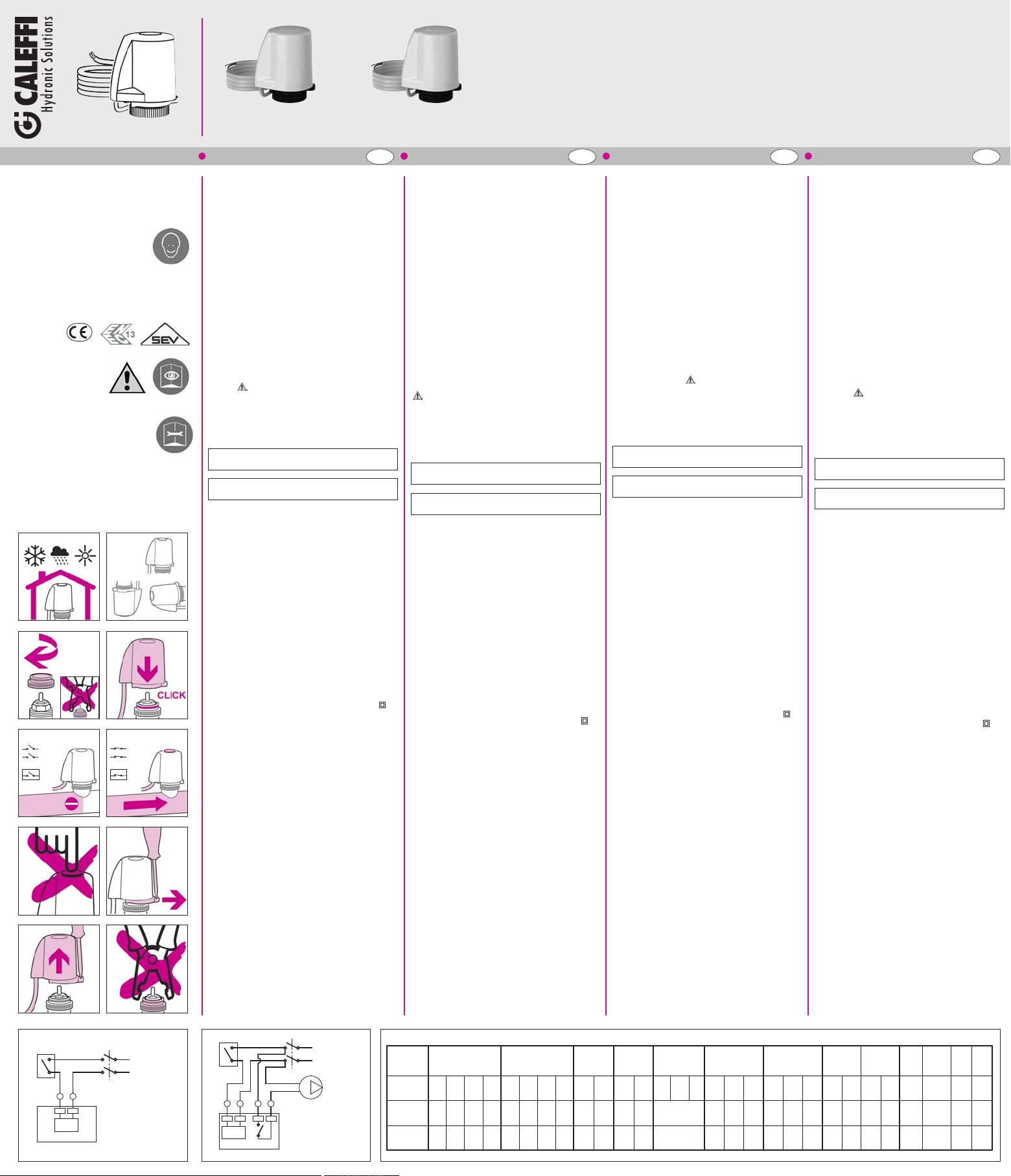
Installazione (fig. A - B - C - D)
Avvitare la ghiera fino a battuta.
Utilizzo (fig. E - F - G)
- Indicatore posizione apertura: verde
Utilizzo con microinterruttore ausiliario. Il microinterruttore
*
ausiliario è azio nato dal movimento d i a pertura del coman do
elettrotermico. Il microinterruttore ausiliario si chiude per un
valore medio di apertura del comando elettrotermico dell’80%.
Smontaggio (fig. H - I - L)
Schema elettrico:
- senza micro aux (fig. M)
- con micro aux (fig. N)
1 = Marrone 2 = Blu 3 = Nero 4 = Grigio
Tabella accoppiamenti (fig. O)
Con adattatore cod. F36077
**
VIGENTE
grigio RAL 9002 (cod. 656412/414)
24 V (ac) - 24 V (dc) = 125 mA
INSTRUCTIONS FOR INSTALLATION,
COMMISSIONING AND
MAINTENANCE
Thank you for choosing our product.
Further technical details relating to this
device are available at
www.caleffi.com
LOW CONSUMPTION
THERMO-ELECTRIC ACTUATOR
General
These series of thermo-electric actuators carry the
CE marks in accordance with Directives 2006/95/EC and
2004/108/EC.
Warnings
The following instructions must be read and understood
before installing and maintaining the product. The symbol
means:
CAUTION! FAILURE TO FOLLOW THESE INSTRUCTIONS
COULD RESULT IN A SAFETY HAZARD!
Safety
The safety instructions provided in the specific document
supplied MUST be observed.
LEAVE THIS MANUAL AS A REFERENCE GUIDE
DISPOSE OF THE PRODUCT IN COMPLIANCE WITH
Function
The thermo-electric actuator, coupled with thermostatically preadjusted or thermostatic valves for radiators, with distribution
manifolds for radiant panel systems and radiators and with zone
valves, allows automatic shut-off of the medium under the
control of a room thermostat or of another electrical switch.
Technical specifications
Materials
Protective shell: self-extinguishing polycarbonate
Colour: white RAL 9010 (code 656402/404)
Performance
Normally closed
Electric supply: 230 V (ac) - 24 V (ac) - 24 V (dc)
Starting current: ≤ 250 mA
Running current: 230 V (ac) = 15 mA
Running power consumption: 3 W
Aux. microswitch contact rating
(code 656412/414): 0,8 A (230 V)
Protection class (fitted in all positions): IP 54
Double insulation construction: EC
Operating time 80%: 300 s
Operating time 100%: 600 s
Closing time: 240 s
Aux. microswitch closing time: 300 s
Length of supply cable: 80 cm
Ambient conditions (valve + control)
Medium working temperature range: 5
Ambient temperature:
Operation: 0 - 50°C EN 60721-3-3 Cl. 3K3, max. humidity 85%
Transportation:-10 - 70°C EN 60721-3-2 Cl. 2K2, max. humidity95%
Storage: -5 - 50°C EN 60721-3-1 Cl. 1K2, max. humidity 95%
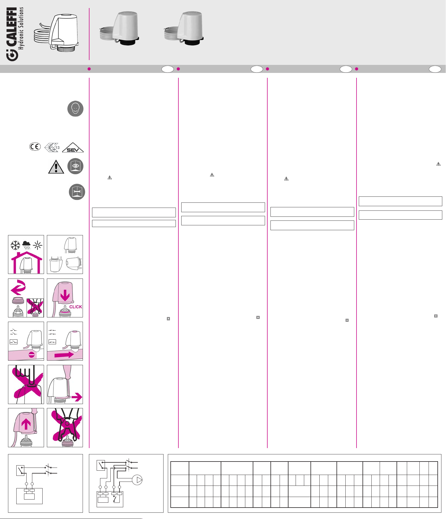
Installation (fig. A - B - C - D)
Fully tighten the ringnut.
Use (fig. E - F - G)
- Opening position indicator: green
Use with auxiliary microswitch. The auxiliary microswitch is
*
activated by the opening movement of the thermo-electric
actuator. The auxiliary microswitch shuts off for an average
thermo-electric actuator opening value of 80%.
Disassembly (fig. H - I - L)
Wiring diagram:
- without aux. microswitch
- with aux. microswitch (fig. N)
1 = Brown 2 = Blue 3 = Black 4 = Grey
Table of couplings (fig. O)
With adapter code F36077
**
FOR THE USER
CURRENT LEGISLATION
grey RAL 9002 (code 656412/414)
24 V (ac) - 24 V (dc) = 125 mA
(fig. M)
–
75°C
CONSIGNES POUR L’INSTALLATION,
LA MISE EN SERVICE ET L’ENTRETIEN
Nous vous remercions d'avoir choisi
ce produit.
Pour plus d'informations, consulter le
site www.caleffi.com
TÊTE ÉLECTROTHERMIQUE
À BASSE CONSOMMATION
Généralités
Ces séries de têtes électrothermiques portent la marque
CE conformément aux directives 2006/95/CE et
2004/108/CE.
Avertissements
S’assurer d’avoir lu et compris les instructions suivantes
avant de procéder à l’installation et à l’entretien du
dispositif. Le symbole signifie :
ATTENTION ! LE NON-RESPECT DE CES CONSIGNES
PEUT S'AVÉRER DANGEREUX !
Sécurité
Respecter impérativement les consignes de sécurité
citées sur le document qui accompagne la tête.
LAISSER CE MANUEL
AU SERVICE DE L’UTILISATEUR
JETER LE PRODUIT CONFORMÉMENT AUX NORMES
Fonction
La tête électrothermique, accouplée avec des robinets
thermostatisables ou thermostatiques pour radiateurs, avec
collecteurs de distribution pour installations de planchers
chauffants et de radiateurs, permet de gérer une zone à l'aide
d'un thermostat d’ambiance ou d’un autre interrupteur
électrique.
Caractéristiques techniques
Matériaux
Capuchon de protection : polycarbonate auto extinguible
Couleur : blanc RAL 9010 (réf. 656402/404)
Performances
Normalement fermée
Alimentation : 230 V (ca) - 24 V (ca) - 24 V (cc)
Courant d'appel : ≤ 250 mA
Courant en régime établi : 230 V (ac) = 15 mA
Puissance absorbée en régime établi : 3 W
Pouvoir de coupure contact auxiliaire
(réf. 656412/414) 0,8 A (230 V)
Indice de protection (assemblé sur toutes les positions) : IP 54
Fabriquée avec une double isolation : CE
Temps d’intervention 80%: 300 s
Temps d’intervention 100%: 600 s
Temps de fermeture : 240 s
Temps de fermeture contact aux. : 300 s
Longueur du câble d’alimentation : 80 cm
Conditions ambiantes (robinet + tête)
Plage de température du liquide : 5÷75°C
Température ambiante :
Fonctionnement : 0÷50°C EN 60721-3-3 Cl. 3K3, humidité maxi 85%
Transport : -10÷70°C EN 60721-3-2 Cl. 2K2, humidité maxi 95%
Stockage : -5÷50°C EN 60721-3-1 Cl. 1K2, humidité maxi 95%
Installation (fig. A - B - C - D)
Serrer la bague à fond.
Emploi (fig. E - F - G)
- Indicateur de position d’ouverture : vert
Avec contact auxiliaire. Le contact auxiliaire est actionné par
*
le mouvement d’ouverture de la tête électrothermique. Le
contact auxiliaire se ferme à une valeur moyenne d’ouverture de
la tête électrothermique de 80%.
Démontage (fig. H - I - L)
Schéma électrique :
- sans contact aux
- avec contact aux (fig. N)
1 = Marron 2 = Bleu 3 = Noir 4 = Gris
Tableau des accouplements (fig. O)
Avec adaptateur réf. F36077
**
EN VIGUEUR
gris RAL 9002 (réf. 656412/414)
24 V (ac) - 24 V (dc) = 125 mA
(fig. M)
INSTALLATIONS-,
INBETRIEBNAHME- UND
WARTUNGSANWEISUNGEN
Wir bedanken uns, dass Sie sich für
unser Produkt entschieden haben.
Weitere technische Details zu diesem
Gerät finden Sie unter www.caleffi.com
ELEKTROTHERMISCHER
GERINGER STROMVERBRAUCH
Allgemeines
Diese Serie elektrothermischer Stellantriebe verfügt über
die CE-Kennzeichnung gemäß den Richtlinien 2006/95/EG
und 2004/108/EG.
Hinweis
Die folgenden Anweisungen müssen vor Installation und
Wartung des Gerätes gelesen und verstanden worden sein.
Das Symbol bedeutet:
ACHTUNG! EINE MISSACHTUNG DIESER ANWEISUNGEN
KANN GEFAHRENSITUATIONEN VERURSACHEN!
Sicherheit
Die in der beigelegten Dokumentation enthaltenen
Sicherheitsanweisungen müssen beachtet werden.
DEN GELTENDEN VORSCHRIFTEN ENTSPRECHEND
Funktion
Der elektrische Stellantrieb 6562.. ist zum Anbau an
Thermostatventilunterteile, Ventilunterteile in Heizkreisverteilern
und Zonenventile vorgesehen. Die Regelung erfolgt durch
automatisches Öffnen und Schliessen des Ventils. Die
Ansteuerung erfolgt über Raumthermostate bzw. andere
elektrische Schalter. Funktion - stromlos zu.
Technische Eigenschaften
Materialien
Schutzkappe: selbstlöschendes Polycarbonat
Farbe: Weiß RAL 9010 (Art.-Nr. 656402/404)
Leistungen
Stromlos geschlossen
Betriebsspannung: 230 V (ac) - 24 V (ac) - 24 V (dc)
Anlaufstrom: ≤ 250 mA
Stromaufnahme im Normalbetrieb: 230 V (ac) = 15 mA
Leistungsaufnahme im Normalbetrieb: 3 W
Stromfestigkeit Hilfsschalterkontakte
(Art.Nr. 656412/414): 0,8 A (230 V)
Schutzart: IP 54
Konstruktion mit doppelter Isolierung: CE
Öffnungs- und Schließzeit 80%: 300 s
Öffnungs- und Schließzeit 100%: 600 s
Schliesszeit: 240 s
Aux Mikroschalter, Schliesszeit: 300 s
Kabellänge: 80 cm
Umgebungsbedingungen (Ventil + Antrieb)
Temperaturbereich des Mediums: 5÷75°C
Umgebungstemperatur:
Betrieb: 0÷50°C EN 60721-3-3 Kl. 3K3, max. Feuchtigkeit 85%
Transport:-10÷70°C EN 60721-3-2 Kl. 2K2, max. Feuchtigkeit 95%
Lagerung: -5÷50°C EN 60721-3-1 Kl. 1K2, max. Feuchtigkeit 95%
Installation (Abb. A - B - C - D)
Die Nutmutter bis zum Anschlag eindrehen.
Betrieb (Abb. E - F - G)
- Positionsanzeige Öffnen: Grün
Betrieb mit Hilfsschalter. Der Hilfsschalter wird durch die
*
Öffnungsbewegung des elektrothermischen Stellantriebs
betätigt. Der Hilfsschalter schließt bei einem mittleren
Öffnungswert von 80%.
Ausbau (fig. H - I - L)
Schaltplan:
- ohne Hilfsschalter (Abb. M)
- mit Hilfsschalter (Abb. N)
1 = Braun 2 = Blau 3 = Schwarz 4 = Grau
Tabelle der Verbindungen (Abb. O)
**
STELLANTRIEB
DIESE ANLEITUNG IST DEM
BENUTZER AUSZUHÄNDIGEN
ENTSORGEN
Grau RAL 9002 (Art.-Nr. 656412/414)
Mit Adapter Art.-Nr. F36077
24 V (ac) - 24 V (dc) = 125 mA
M
N
O
Page 2
656402 230 V
Series
3/8” 1/2” 3/4” 1”
**
338-401
185 210 270 440
250 250 180 120
DN
Kv
0,01
(l/h)
∆p
MAX
(kPa)
3/8” 1/2” 3/4” 1”
**
339-402
110 145 225 420
250 250 180 120
**
421-425
1/2” 3/4” 1”
**
455
200/110
100
3/8” 1/2” 3/4”
220-222
180 200 255
250 250 180
3/8” 1/2” 3/4”
221-223
100 135 200
250 250 180
3/8” 1/2”
224-227
80 125
250 250
3/8” 1/2”
225
85 125
250 250
663
670
671
1 1/4” 1”
287 240
250 250
662
1”
410
180
3/8” 1/2”
130 140
250 250
666 S1
668 S1
1 1/4”
250
250
**
422-426
3/8” 1/2”
90 100
250 250
Ω
3 W
max 0,8 A
L
N
230 V (ac)
24 V (ac)
24 V (dc)
1
2
3
4
Ω
3 W
L
N
230 V (ac)
24 V (ac)
24 V (dc)
1
2
L
N
˜
ON
MICRO
ON
L
N
˜
OFF
MICRO
OFF
656404 24 V
656412 230 V with microswitch
656414 24 V with microswitch
www.caleffi.com
©
Copyright 2011 Caleffi
A
C
E
*
G H
I L
M
B
D
F
*
ESPAÑOL PORTUGUÊS NEDERLANDS РУССКИЙ
ES PT NL RU
INSTRUCCIONES DE INSTALACIÓN,
PUESTA EN MARCHA Y
MANTENIMIENTO
Gracias por escoger un producto de
nuestra marca.
Encontrará más información sobre
este dispositivo en la página
www.caleffi.com.
CABEZAL ELECTROTÉRMICO
A BAJA ABSORCIÓN
Generalidades
Los cabezales electrotérmicos de esta serie llevan el
marcado CE de acuerdo con las directivas 2006/95/CE y
2004/108/CE.
Advertencias
Estas instrucciones deben leerse y comprenderse antes de
realizar la instalación y el mantenimiento del producto.
El símbolo significa:
¡ATENCIÓN! EL INCUMPLIMIENTO DE ESTAS
INSTRUCCIONES PUEDE SER PELIGROSO.
Seguridad
Es obligatorio respetar las instrucciones de seguridad
indicadas en el documento específico que se entrega con
el producto.
ENTREGAR ESTE MANUAL
AL USUARIO
DESECHAR SEGÚN LA NORMATIVA LOCAL
Función
El cabezal electrotérmico, combinado con válvulas
termostatizables o termostáticas para radiadores, con
colectores de distribución para sistemas de paneles radiantes y
radiadores o con válvulas de zona, corta automáticamente el
paso del fluido tras una señal del termostato de ambiente o de
otro interruptor eléctrico.
Características técnicas
Materiales
Carcasa protectora: policarbonato autoextinguible
Color: blanco RAL 9010 (cód. 656402/404)
Prestaciones
Normalmente cerrado
Alimentación eléctrica: 230 V (ac) - 24 V (ac) - 24 V (dc)
Corriente de arranque: ≤ 250 mA
Corriente en régimen 230 V (ac) = 15 mA
Potencia absorbida en régimen: 3 W
Capacidad contactosmicr. auxiliar (cód. 656412/414): 0,8 A (230 V)
Grado de protección (en cualquier posición de montaje): IP 54
Doble aislamiento: CE
Tiempo de actuación 80%: 300 s
Tiempo de actuación 100%: 600 s
Tiempo de cierre: 240 s
Tiempo de cierre microrruptor: 300 s
Longitud cable de alimentación: 80 cm
Condiciones ambientales (válvula + cabezal)
Campo de temperatura del fluido: 5÷75 °C
Temperatura ambiente
Funcionamiento: 0÷50 °C EN 60721-3-3 Cl. 3K3, hum. máx. 85 %
Transporte: -10÷70 °C EN 60721-3-2 Cl. 2K2, hum. máx. 95 %
Almacenamiento:-5÷50 °C EN 60721-3-1 Cl. 1K2, hum. máx. 95 %
Montaje (figs. A, B, C y D)
Enroscar el anillo hasta el tope.
Utilización (figs. E, F y G)
- Indicador de posición de apertura: verde
Uso con microinterruptor auxiliar. El microinterruptor auxiliar
*
se acciona con el movimiento de apertura del cabezal
electrotérmico. El microinterruptor auxiliar se cierra cuando el
cabezal electrotérmico se abre aproximadamente al 80 %.
Desmontaje (figs. H, I y L)
Esquema eléctrico:
- sin micr. auxiliar (fig. M)
- con micr. auxiliar (fig. N)
1 = marrón 2 = azul 3 = negro 4 = gris
Acoplamientos (fig. O)
Con adaptador cód. F36077
**
N
gris RAL 9002 (cód. 656412/414)
24 V (ac) - 24 V (dc) = 125 mA
INSTRUÇÕES PARA A INSTALAÇÃO,
COLOCAÇÃO EM FUNCIONAMENTO
E MANUTENÇÃO
Agradecemos a preferência na
selecção deste produto.
Dados técnicos adicionais sobre este
dispositivo encontram-se disponíveis
no site www.caleffi.com.
COMANDO ELECTROTÉRMICO
DE BAIXO CONSUMO
Generalidades
Esta série de comandos electrotérmicos possui a marca
CE segundo as das directivas 2006/95/CE e 2004/108/CE.
Advertências
As instruções que se seguem devem ser lidas e
compreendidas antes da instalação e da manutenção do
produto. O símbolo significa:
ATENÇÃO! O INCUMPRIMENTO DESTAS INSTRUÇÕES
PODERÁ ORIGINAR UMA SITUAÇÃO DE PERIGO!
Segurança
É obrigatório respeitar as instruções de segurança
indicadasno documentoespecíficocontidona embalagem.
DEIXAR O PRESENTE MANUAL
À DISPOSIÇÃO DO UTILIZADOR
ELIMINAR EM CONFORMIDADE COM AS NORMAS EM
Função
O comando electrotérmico, em acoplamento com válvulas
termostatizáveis ou termostáticas para radiadores, com
colectores de distribuição para instalações de chão radiante e
radiadores, e com válvulas de zona, torna automática a
intercepção do fluido sob comando de um termóstato ambiente
ou de outro interruptor eléctrico.
Características técnicas
Materiais
Borracha protectora: policarbonato auto-extinguível
Cor: branco RAL 9010 (cód. 656402/404)
Desempenho
Normalmente fechado
Alimentação: 230 V (ac) - 24 V (ac) - 24 V (dc)
Corrente inicial de ligação: ≤ 250 mA
Corrente em funcionamento: 230 V (ac) = 15 mA
Consumo em funcionamento: 3 W
Corrente contactos micro auxiliar (cód. 656412/414):0,8A (230V)
Grau de protecção (montado em todas as posições): IP 54
Construção com duplo isolamento: CE
Tempo de intervenção 80%: 300 s
Tempo de intervenção 100%: 600 s
Tempo de fecho: 240 s
Tempo de fecho micro-interruptor auxiliar: 300 s
Comprimento do cabo de alimentação: 80 cm
Condições ambientais (válvula + comando)
Campo de temperatura fluido: 5÷75°C
Temperatura ambiente:
Funcionamento:0÷50°C EN 60721-3-3 Cl. 3K3, humidade máx. 85%
Transporte: -10÷70°C EN 60721-3-2 Cl. 2K2, humidade máx. 95%
Armazenamento:-5÷50°CEN 60721-3-1 Cl. 1K2, humidademáx.95%
Instalação (fig. A - B - C - D)
Apertar a rosca até ao batente.
Utilização (fig. E - F - G)
- Indicador de posição de abertura: verde
Utilização com micro-interruptor auxiliar. O micro-interruptor
*
auxiliar é accionado pelo movimento de abertura do comando
electrotérmico. O micro-interruptor auxiliar fecha-se no caso de
um valor médio de aberturado comando electrotérmico de 80%.
Desmontagem (fig. H - I - L)
Esquema eléctrico:
- sem micro auxiliar
- com micro auxiliar (fig. N)
1 = Castanho 2 = Azul 3 = Preto 4 = Cinzento
Tabela de ligações (fig. O)
Com adaptador cód. F36077
**
O
VIGOR
cinzento RAL 9002 (cód. 656412/414)
24 V (ac) - 24 V (dc) = 125 mA
(fig. M)
INSTRUCTIES VOOR INSTALLATIE,
INBEDRIJFSTELLING EN
ONDERHOUD
We bedanken U voor de keuze van ons
product.
Nadere technische details omtrent dit
toestel, vindt U op onze site
www.caleffi.com.
ELEKTROTHERMISCHE BEDIENING
Algemeen
Deze serie elektrothermische bedieningen is voorzien van
het CE keurmerk in overeenstemming met de richtlijnen
2006/95/CE en 2004/108/CE.
Waarschuwingen
Gelieve de volgende aanwijzigingen goed te lezen alvorens
het product te installeren of onderhoud te verrichten. Het
symbool betekent:
LET OP! NIET NAVOLGEN VAN DEZE AANWIJZINGEN
KAN GEVAARLIJK ZIJN!
Veiligheid
Het is verplicht de veiligheidsvoorschriften op te volgen die
vermeld staanop hetspecifieke document in de verpakking.
DE GEBRUIKER DIENT ALS NASLAGWERK VOOR DE
HET PRODUCT VERWIJDEREN IN OVEREENSTEMMING
Functie
In combinatie met thermostatische of thermostatiseerbare
radiatorventielen, met verdeelcollectoren voor systemen met
straalpanelen en radiatoren en met zoneventielen, dient de
elektrothermische bediening voor automatisch afsluiten van de
vloeistof. Of op commando van de omgevingsthermostaat of
andere schakelaar.
Technische gegevens
Materialen
Behuizing: zelfblussend polycarbonaat
Kleur: wit RAL 9010 (code 656402/404)
Prestaties
Normaal gesloten
Voeding: 230 V (ac) - 24 V (ac) - 24 V (dc)
Piekstroom:
Bedrijfsstroom:
Energieverbruik: 3 W
Capaciteitextramicroschakelaar (code 656412/414): 0,8 A (230 V)
Beschermingsgraad (assemblage in elke stand): IP 54
Constructie met dubbele isolatie: CE
Werkingstijd
Werkingstijd
Sluitingstijd: 240 s
Sluitingstijd micro aux.: 300 s
Lengte voedingskabel: 80 cm
Omgevingscondities (ventiel + bediening)
Temperatuurbereik vloeistof: 5÷75°C
Omgevingstemperatuur:
Werking: 0÷50°C EN 60721-3-3 Cl. 3K3, max. vochtigheid85%
Transport:-10÷70°C EN 60721-3-2 Cl. 2K2, max. vochtigheid 95%
Opslag: -5÷50°C EN 60721-3-1 Cl. 1K2, max. vochtigheid 95%
Installatie (afb. A - B - C - D)
De moer volledig vastdraaien
Gebruik (afb. E - F - G)
- Aanduiding openingsstand: groen
Gebruik met extra microschakelaar. De extra microschakelaar
*
wordt aangestuurd bij het openen van de elektrothermische
bediening. De extra microschakelaar sluit bij een gemiddelde
openingswaarde van de elektrothermische bediening van 80%.
Demontage (afb. H - I - L)
Schakelschema:
- zonder extra micro
- met extra micro (afb. N)
1 = Bruin 2 = Blauw 3 = Zwart Grijs
Aansluittabel (afb. O)
**
LAAG VERBRUIK
GEBRUIKER
MET DE GELDENDE WETGEVING
grijsRAL 9002 (code 656412/414)
230 V (ac) = 15 mA
24 V (ac) - 24 V (dc) = 125 mA
80%: 300 s
100%: 600 s
(afb. M)
Met adapter code F36077
≤ 250 mA
ИНСТРУКЦИИ ПО УСТАНОВКЕ, ВВОДУ В
ЭКСПЛУАТАЦИЮ И ТЕХОБСЛУЖИВАНИЮ
Благодарим Вас за выбор нашего
изделия.
За дополнительной технической
информацией по данному устройству
обращайтесь к Интернет-сайту
www.caleffi.com.
ЭЛЕКТРОТЕПЛОВОЙ ПРИВОД
С НИЗКИМ ПОТРЕБЛЕНИЕМ
Общие сведения
Эти серии электротепловых приводов имеют маркировку CE в
соответствии с директивами2006/95/CE и 2004/108/CE.
Предупреждения
Данные инструкции должны быть прочитаны и усвоены до
начала монтажа и техобслуживания изделия. Символ
означает:
ВНИМАНИЕ! НЕСОБЛЮДЕНИЕ ДАННЫХ ИНСТРУКЦИЙ МОЖЕТ
ПРИВЕСТИ К СОЗДАНИЮ ОПАСНЫХ СИТУАЦИЙ!
Безопасность
Обязательно соблюдайте инструкции по безопасности,
приведенные в специальном документе, входящем в
упаковку.
ДАННЫЕ ИНСТРУКЦИИ ДОЛЖНЫ НАХОДИТЬСЯ
В РАСПОРЯЖЕНИИ ПОЛЬЗОВАТЕЛЯ
УТИЛИЗАЦИЯ ДОЛЖНА ПРОВОДИТЬСЯ СОГЛАСНО
ДЕЙСТВУЮЩИМ НОРМАТИВАМ
Назначение
ЭЛЕКТРОТЕПЛОВОЙ ПРИВОД в сочетании с клапанами с
термостатической опцией или термостатическими клапанами
для радиаторов, с распределительными коллекторами для
систем панельного и радиаторного отопления и зонными
клапанами, выполняет функцию перевода в автоматический
режим отсекания подачи теплоносителя на привод термостата
среды или другого электрическогопереключателя.
Технические характеристики
Материалы
Защитная оболочка: самогасящийся поликарбонат
Цвет: белый RAL 9010 (код 656402/404)
Эксплуатационные показатели
Нормально закрытый
Электропитание:230 В (пер. ток) - 24 В (пер. ток)- 24 В (пост.ток)
Пусковой ток: ≤ 250 mA
Токв рабочем режиме: 230 В (пер. ток) = 15 мА
Потребляемая мощность в рабочем режиме: 3 Вт
Емкость контактов вспомогательного
микровыключателя (код 656412/414): 0,8 A (230 В)
Степень защиты (при сборке в любом положении): IP 54
Конструкция с двойной изоляцией: CE
Время открывания 80%: 300 сек.
Время открывания 100%: 600 сек.
Время закрывания: 240 сек.
Время закрывания вспомогательного
микровыключателя: 300 сек.
Длина токоподводящего кабеля: 80 см
Условияокружающей среды (клапан + привод)
Диапазонтемпературы жидкости: 5÷75°C
Температура окружающейсреды:
Функционирование:0÷50°CEN 60721-3-3Cl.3K3,макс. влажность85%
Транспортировка:-10÷70°C EN 60721-3-2Cl. 2K2, макс.влажность95%
Хранение: -5÷50°C EN 60721-3-1Cl. 1K2, макс. влажность 95%
Монтаж (рис. A - B - C - D)
Завинтить круглую гайку до упора.
Использование (рис. E - F - G)
- Указатель открытого положения: зеленый
Использование со вспомогательным микровыключателем.
*
Вспомогательный микровыключательприводитсяв действиеза
счет открытия электротеплового привода. Вспомогательный
микровыключательзамыкается при среднемзначенииоткрытия
электротеплового привода,равном80%.
Демонтаж(рис. H - I - L)
Электрическая схема:
- без вспомогательного
микровыключателя (рис. M)
- со вспомогательным
микровыключателем (рис. N)
1 = Коричневый 2= Синий 3 = Черный 4 = Серый
Таблицакомбинаций (рис. O)
C адаптером код F36077
**
серый RAL 9002 (код 656412/414)
24 В (пер. ток) - 24 В (пост. ток) = 125 мA
 Loading...