

Page 1
5
U
L
®
C
www.cale.com
68235.0
Flow Switch
Copyright 2018 Caleffi
©
Function
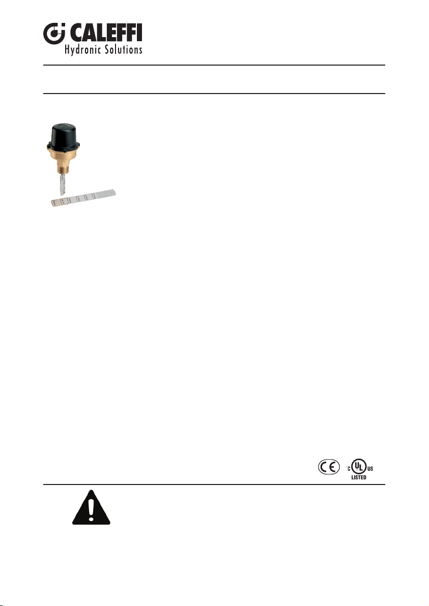
The Caleffi Series 626 water flow switch detects the presence or absence
of flow in piping of heating, air conditioning, cooling and water treatment
systems as well as in pumping and process systems. In heating systems,
the flow switch is normally used to shut off the burner of the boiler whenever
there is no circulation of the carrier fluid in the boiler circuit. A lack of
circulation can damage criti
cal components and impair the operation of
temperature sensitive safety and protection devices.
This item is designed for use in closed hydronic systems. Do not use in plumbing applications. This
item does not meet the low-lead plumbing standards of U.S. and Canada.
General Characteristics
A stainless steel bellows separates the electrical and hydronic sections, preventing the possibility
of contact of the fluid with the electrical components. Stainless steel is used in the construction of
many key parts, including the bellows, which protects the switch from corrosion.
With a protection classification of NEMA type 5 (IP54), the switch can be used in particularly
humid and dusty environments. The cover is made of a special non-combustible plastic material.
The normally open and normally closed contacts on the switch enable any electrical device to be
switched on or off as required at the operating flow rate. The operating point can be easily adjusted
with the calibration screw.
Technical Characteristics
Connection size: 1” NPT male
Maximum operating pressure: 150 psig (10 bar)
Maximum temperature of the fluid: 250° F (120°C)
Minimum temperature of the fluid: -20° F (-30°C)
Maximum ambient temperature: 130° F (55°C)
Suitable for pipes: 1” to 8” (25 to 200 mm)
626 Series
Electrical Data
Max Voltage: 250 VAC
Current: 15 A
Electrical connection: 1/2” NPT threaded
Protection class: NEMA type 5 (IP54)
Certification Mark:
SAFETY INSTRUCTION
This safety alert symbol will be used in this manual to draw attention to
safety related instructions. When used, the safety alert symbol means
ATTENTION! BECOME ALERT! YOUR SAFETY IS INVOLVED!
FAILURE TO FOLLOW THESE INSTRUCTIONS MAY RESULT IN
A SAFETY HAZARD.
CONSIGNE DE SÉCURITÉ
Ce symbole d'avertissement servira dans ce manuel à attirer l'attention sur la sécurité concernant
instructions. Lorsqu'il est utilisé, ce symbole signifie ATTENTION ! DEVENEZ ALERTE !
VOTRE SÉCURITÉ EST EN JEU ! NE PAS SUIVRE CES INSTRUCTIONS PEUT
PROVOQUER UN RISQUE DE SÉCURITÉ.
Page 2
WARNING: This product can expose you to chemicals including lead, which is
known to the State of California to cause cancer and birth defects or other
reproductive harm. For more information go to www.P65Warnings.ca.gov.
AVERTISSEMENT: Ce produit peut vous exposer à des produits chimiques
comme le plomb, qui est connu dans l’État de Californie pour causer le cancer,
dommages à la naissance ou autre. Pour plus d’informations rendez-vous
www.P65Warnings.ca.gov.
CAUTION:
All work must be performed by qualified personnel trained in
the proper application, installation, and maintenance of systems in
accordance with all applicable codes and ordinances.
ATTENTION: Tous les travaux doivent être effectués par du personnel
qualifié formé à la bonne application, installation et maintenance des systèmes
conformément aux codes et règlements locaux.
CAUTION:
Over-tightening and breakage can occur with the use of PTFE
pipe joint compounds. PTFE provides lubricity so that care must be
exercised not to over-tighten joints. Failure to follow these instructions
could result in property damage and /or personal injury.
ATTENTION: Un serrage excessif et la rupture peuvent se produire avec l'utilisation
de raccords filetés de tuyaux téflon. Téflon fournit un pouvoir lubrifiant afin qu'il doit
être prudent pour ne pas trop serrer les joints. Suivre ces instructions peut entraîner.
Installations
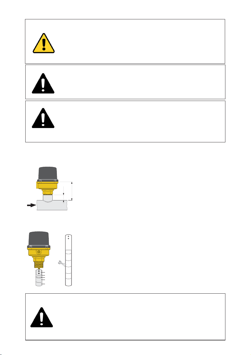
To install the flow switch correctly follow these instructions:
-Select the blade marked with the diameter of the pipe in which the
switch is to be installed;
-Remove any extra pre-fitted blades for larger diameter pipes by
unscrewing the 2 blade attaching screws;
-With pipe diameters of 3” (DN 80) or above, all the pre-fitted blades
3/4”
must be attached in ascending order with the long blade being cut
3 1/8”
to the size corresponding to the desired pipe diameter;
-Fit the flow switch to the pipe, carefully observing the direction of
flow indicated by the arrows stamped on the cover and on the switch
mounting plate. When fitted, the distance between the upper surface
of the pipe and upper surface of the switch mounting plate should
be 3 1/8” (80 mm);
-The tee connection in the pipe can be formed by the direct welding
of a threaded socket;
-This also applies to a 1” (DN 25) diameter pipe, as the blades are
3"-DN 80
designed to be contained in these smaller dimensions.
4"-DN100
-It is however advisable to check that the weld is free from burrs on
5"-DN125
the inside so that the blade can move freely in the tee connection;
1"
1
1
2"
2
6"-DN150
-Whenever possible the flow switch should be installed in the
DN175
position to avoid deposits of impurities which may cause it to
function incorrectly.
8"-DN200
vertical
WARNING:
Electrical shock hazard. Disconnect ALL power sources when
installing or servicing this equipment to prevent electrical shock or
equipment damage. Failure to follow these instructions could result in
property damage and/or personal injury.
ATTENTION: Risque d’électrocution. appareil sous tension. Coupez l’alimentation
électrique avant d’effectuer toute intervention. Le non respect de ces indications
peut provoquer des lésions corporelles ou des dégâts matériels.
Page 3
Electrical Connections
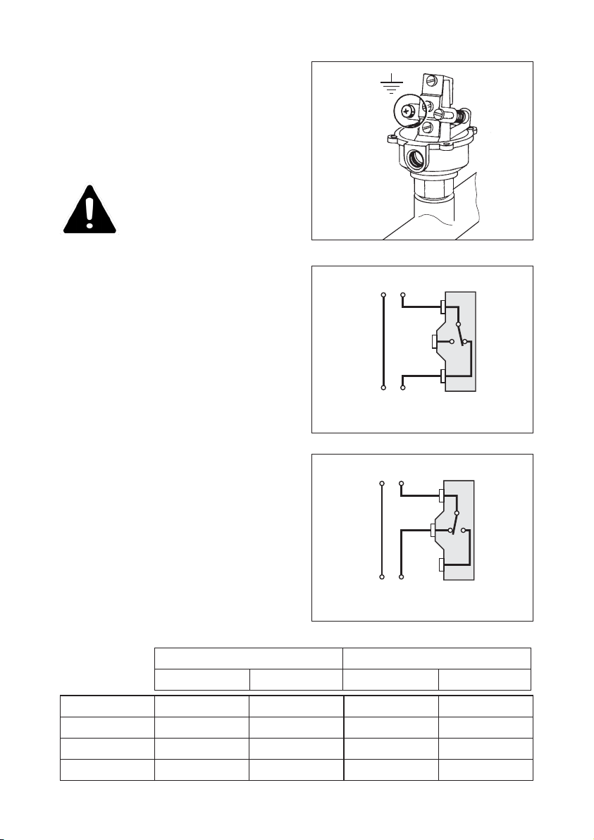
Unscrew the four cover screws and lift off the
outer cover.
Make sure the wires do not
obstruct the function of the
switch mechanism.
Assurez-vous que les fils ne
sont pas
entraver le fonctionnement de la
changer le mécanisme.
Diagrams showing the internal
connections of the micro-switch
with:
Flow switch used to activate a
device when flow stops.
When the decreasing operating flow is reached
or stops the common (black wire) and the
normally open (red wire) contacts open, while
the common (black wire) and the normally
closed (blue wire) contacts close.
Line input
COM
(black)
N.O.
(r ed)
N.C.
(blue)
Switched
output
Flow switch is used to activate a
device when flow starts.
When flow starts and the increasing operating
flow is reached or exceeded, the common
(black wire) and normally open (red wire)
contacts are closed, while the common (black
wire) and the normally closed (blue wire) are
open.
Line input
COM
(black)
N.O.
(r ed)
N.C.
(blue)
Switched
output
Electrical Rating
125 V
AC
250 V
AC
N.C. N.O. N.C. N.O.
Resistive Load 15 A 15 A 15 A 15 A
Inductive Load 15 A 15 A 15 A 15 A
Motor Load 5 A 2.5 A 3 A 1.5 A
Horsepower 1/8 HP 1/8 HP 1/4 HP 1/4 HP
Page 4
Calibration
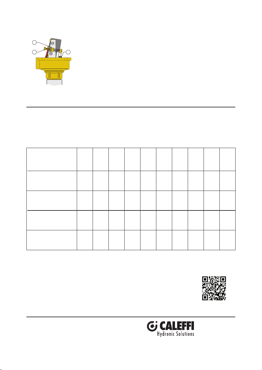
The minimum and maximum operating flow rates are given in the
B
A
C
table below. Adjustments should be carried out as follows: turn
the calibration screw (A) in a clockwise direction for the contacts to
close at higher flow rate values or in a counterclockwise direction for
lower flow rate values. When the adjustment has been made lock the
screw (A) with the locking ring nut (B). Avoid all contact with the
presetting screw (C). An incorrect setting would seriously impair the
operation of the switch.
Operating flow rates: gpm (lpm)
Diameter of pipe
Minimum calibration
Operating flow rate with
increasing flow
Minimum calibration
Operating flow rate with
decreasing flow
Maximum calibration
Operating flow rate with
increasing flow
Maximum calibration
Operating flow rate with
decreasing flow
1"
1 1/4"
5.7 7.5 11.4 13.2 22.0 29.9 44.0
1 1/2"
2"
2 1/2"
3"
4"
61.1
5"
72.6 162
6"
(21.7) (28.4) (43.4) (50.1) (83.5) (113) (167) (232) (275) (618)
4.0 5.5 8.4 9.7 16.3 22.9 37.4
51.5
63.8 145
(15.0) (20.9) (31.7) (36.7) (61.8) (86.8) (142) (197) (242) (551)
12.3 16.7 26.0 29.5 51.5 69.5 94.6
136
189 334
(46.8) (63.5) (98.5) (112) (195) (264) (359) (518) (718) (1269)
11.9 16.3 25.5 29.0 50.6 68.6 92.4
127
158 308
(45.1) (61.8) (96.9) (110) (192) (260) (351) (484) (601) (1169)
Scan to view
Installation Tip
7-19
-18
8"
·
626 Paddle Flow Switch
Caleffi North America, Inc.
3883 West Milwaukee Road
Milwaukee, WI 53208
T: 414.238.2360 F: 414.238.2366
 Loading...