

Page 1
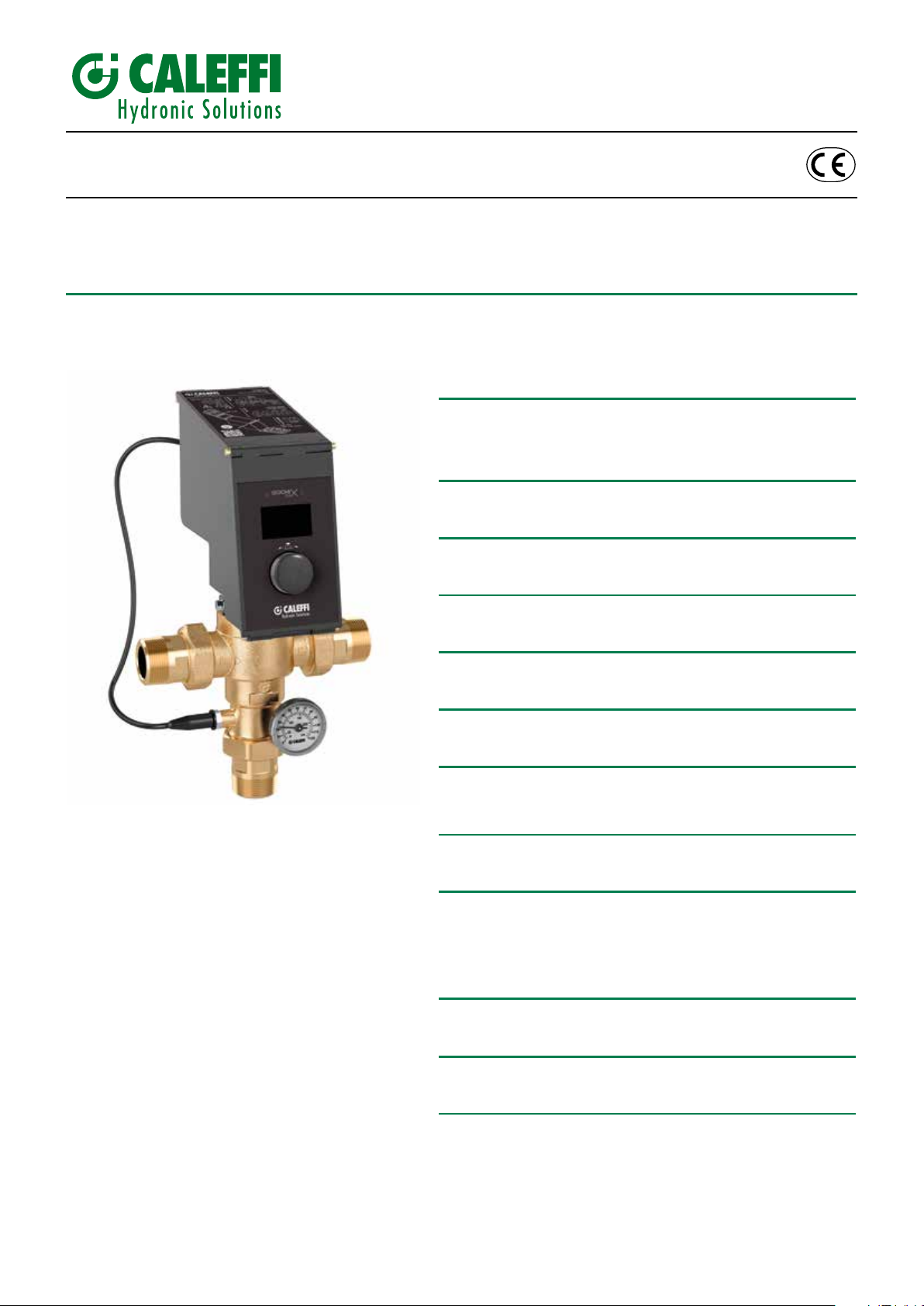
Hybrid electronic mixing valve
H0002123
www.caleffi.com
© Copyright 2017 Caleffi
6000 Series LEGIOMIX 2.0
INSTALLATION AND COMMISSIONING MANUAL
CONTENTS
Product range
Characteristic components
Package content
Technical specifications
Operating principle
Application diagram
Regulator-actuator
Wiring diagrams
Electronic boards description
2
3
4
5
Operating principle
The electronic hybrid mixing valve combines the typical function
of the mechanical thermostatic mixing valve and the management
efciency of an electronic mixing valve in a single device.
The thermostatic mixing valve uses the mechanical action
performed by the internal control thermostatic element, which
responds promptly to any variation in temperature, pressure and
inlet ow rate to quickly restore the mixed water temperature value
at the outlet.
This standard mixing valve is effectively handled by a motorised
actuator that, upon the signal coming from the temperature probes
and under the control of a specic regulator, changes the mixed
water temperature set position.
The electronic regulator, directly on the actuator, allows the
mixed water temperature control according to different functional
programs, both for normal control and for the thermal disinfection
for the prevention of Legionella.
An optional memory system allows recording every minute of ow
temperature, return temperature, alarm and functional statuses,
useful for monitoring the operating status of the entire system.
Appropriate relays are used to manage the alarms and external
appliances, for example for loading accumulation hot water and
switching on/off the recirculation pump.
The regulator is tted for remote control with specic transmission
protocols such as MODBUS, through optional board, for use in
Building Management Systems (BMS).
The device is provided with CE mark in accordance with
directives 2014/35/EU and 2014/30/EU.
Cables pathway
Cables wiring and positioning
Probes connection
Recommended minimum distances
Front panel
Indication on LCD display
Operating status
Plumbing installation
Commissioning
Thermal disinfection
Maintenance
Functional faults
Seals
Troubleshooting
Regulator-actuator replacement/rotation
Thermostatic function
Application diagrams
6
7
8
9
10
11
12
1
Page 2
Product range
6000 series Hybrid electronic mixing valve Sizes DN 15 (1/2”), DN 20 (3/4”), DN 25 (1”), DN 32 (1 1/4”), DN 40 (1 1/2”), DN 50 (2”)
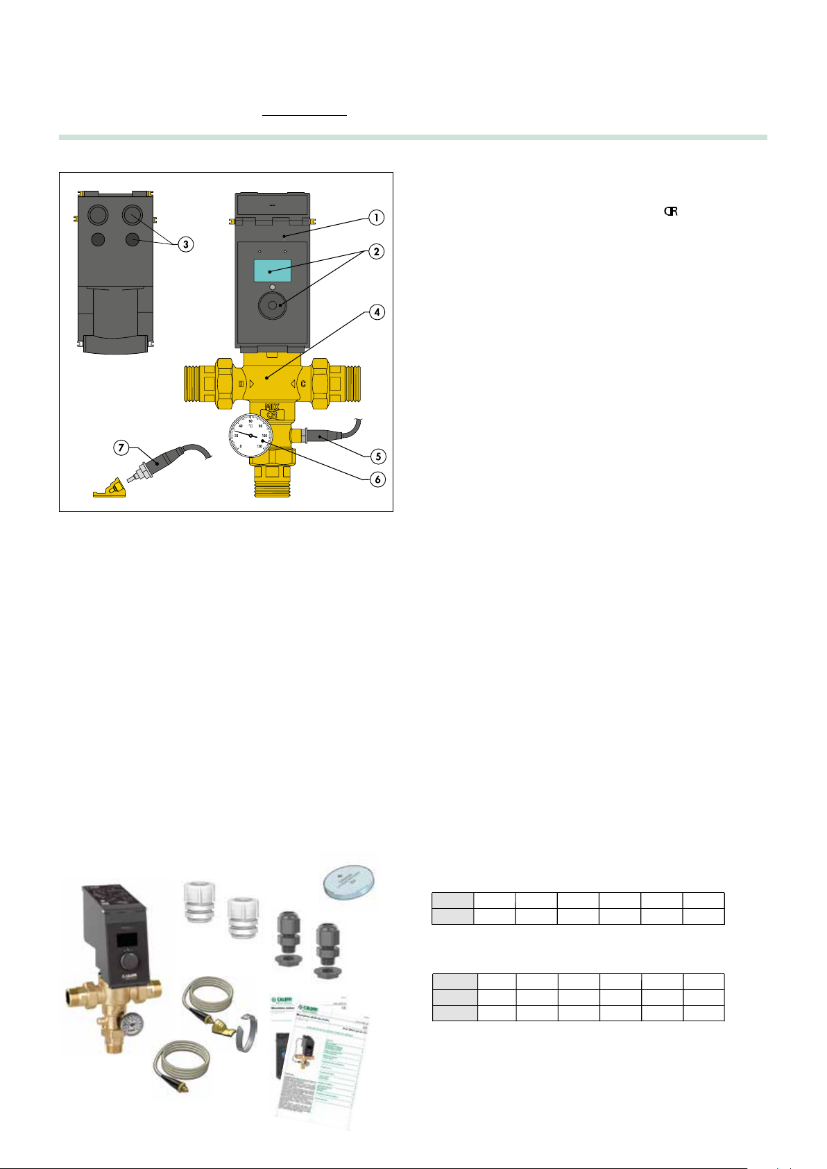
Characteristic components
1 Digital regulator with actuator in single casing
2 Control knob and LCD display
3 Fitted for cable seals and cable glands, with holes
4 Valve body
5 Mixed water temperature probe
6 Mixed water temperature gauge
7 Return temperature probe and probe holder
Package content
• Thermostatic mixing valve complete with regulator-actuator
• Temperature gauge
• Flow probe
• Return contact probe
• Cable seals/cable glands
• Installation and commissioning manual
• Programming manual
• Button battery
At the back of the actuator-regulator, there are 2 holes for mounting
the cable seals and fitted for installing 2 cable glands to ensure IP
54 protection. The cable seals and cable glands have the following
dimensions:
- Cable seals: PG7
- Cable gland: diam. 20 mm
Technical specifications
Valve body
Materials:
Body: dezincification-resistant alloy
EN 1982 CC770S
Obturator: PPSG40
Hydraulic seals: EPDM
Spring: stainless steel EN 10270-3 (AISI 302)
Maximum working pressure (static): 10 bar
Maximum inlet temperature: 90°C
Temperature gauge scale: 0 – 120°C
Connections: 1/2” - 2” M (ISO 10226-2) with union
Regulator-actuator
Material:
Housing: PA6G30 anti-UV black
Covers: PA6G30 anti-UV black
Electric supply: 230 V (ac) 50/60 Hz
Power consumption: 6,5 VA
Adjustment temperature range: 35 – 65°C
Disinfection temperature range: 50 – 85°C
Ambient temperature range:
- Operation: 0-50°C EN 60721-3-3 Cl. 3K3 max. humidity 85%
- Transportation: -30-70°C EN 60721-3-2 Cl. 2K3 max. humidity 95%
- Storage: -20-70°C EN 60721-3-1 Cl. 1K3 max. humidity 95%
Protection class: IP 54
Contact rating:
- Relay OUT1, OUT2, OUT3: 5(2) A / 250 V
- Digital inputs: without potential
Fuses: self-resettable non-replaceable (only for control unit)
Battery: CR2032 225 mAh - life approximately 1 year
(for only keeping date and time in the absence of network)
Optional battery:
ER AA Lithium - Thionyl chloride 3.6 V lasting about 10 years
(for only keeping date and time in the absence of network)
Conforms to Directives: CE
Insulation class: Class II
Temperature probes
Body material: stainless steel
Type of sensitive element: NTC
Working temperature range: -10 – 125°C
Resistance: 10000 Ohm at 25°C
Time constant: 2,5
Max. distance for flow or recirculation probe: 150 m cable 2x1
250 m cable 2x1,5
Mixing valve performance
Accuracy: ± 2°C
Max. working pressure (dynamic): 5 bar
Max. inlet pressure ratio (H/C or C/H): 2:1
Size
Kv (m3/h)
1/2"
4,3
3/4"
4,3
1”
7,6
1 1/4”
10,0
1 1/2”
13,02”18,0
RECOMMENDED flow rates to ensure stable operation and an
accuracy of ± 2°C
Size
Min (m3/h)
Max (m3/h)*
*
Δp = 1,5 bar
1/2"
0,6
5,3
3/4"
0,6
5,3
1”
1,2
9,3
1 1/4”
1,5
12,5
1 1/2”
1,5
16,0
2”
2,0
22,1
2
Page 3
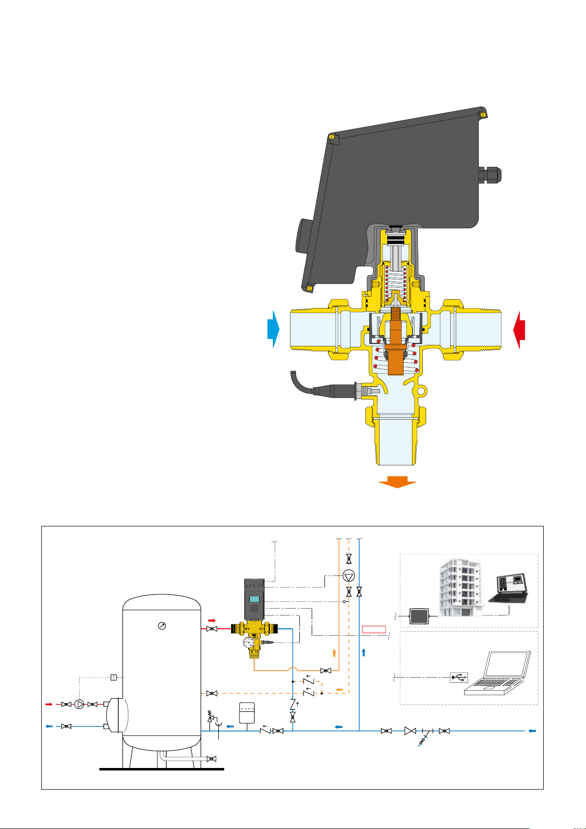
Operating principle
At the inlets the mixing valve has the hot water from the storage and
the cold water from the water mains. At the outlet there is the flow
mixed water. By means of a specific probe, the regulator measures
the temperature of the mixed water at the valve outlet and actuates
an obturator in order to maintain the setting. Temperature fluctuations
caused by flow rate or pressure variations are compensated by the
thermostat in the valve. The appliance has a built-in digital clock,
which can be used to set anti-legionella programs to disinfect
the water system and to manage a recirculation pump. The
system is disinfected by raising the water temperature to a specific
value for a set time duration. For the best thermal disinfection
control, in this type of system it may also be necessary to measure
the temperature of the water returning from the distribution network,
using the recirculation probe. When this measurement is available,
it is used to check and control the temperature reached over all
or part of the network, since the probe may be located at a significant
remote point of the system. The appliance is equipped with RS-485
interface (optional), with MODBUS protocol, for readouts and
remote setting. To use the device, it is necessary to configure the
MODBUS system with the addresses of the registers used by the
device (PC software is available).
Application diagram
COLD
HOT
MIXTURE
BMS
MODBUS
3
Page 4
LEGIOMIX
2.0
Series 6000
T
AMB.
0÷50°C
L - N: 230 V
˜
6,5 VA
IP 54
CS 176
CS 180
CS 179 (OPZ)
L N
NO C NC NO C NO C
CS 176
μ
5(2) A 250 V
˜
230 V
˜
50 Hz
ALARM
OUT1OUT3OUT
2
RETURN
PROBE
MIXED
PROBE
T2
RS485
BA
IN 2 T1IN 1
CS 180
CS 179 (OPZ)
Cale S.p.A.
S.R. 229 n° 25
28010 Fontaneto d’Agogna
Italy
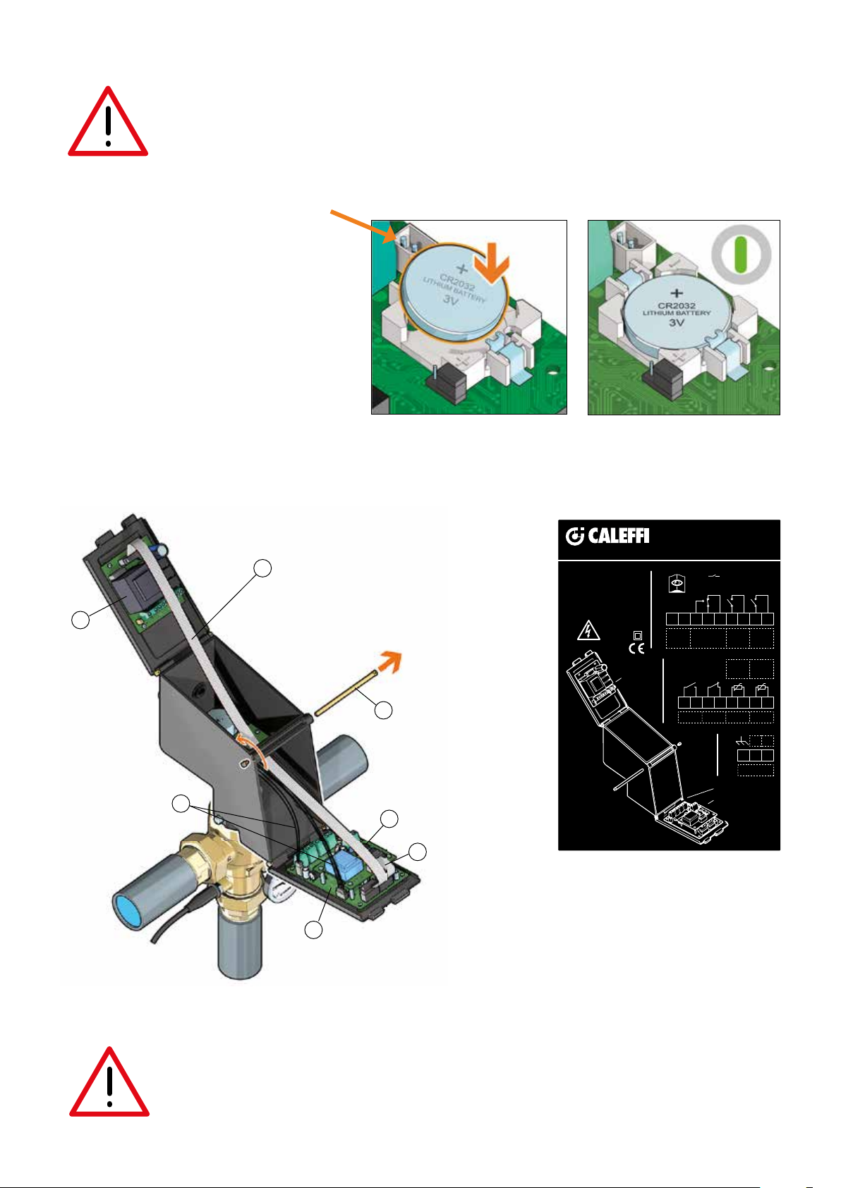
Regulator-actuator
Battery installation
Before connecting the power supply, insert the battery supplied, type CR 2032. The presence of the battery
allows the clock continuous updating. In case of low or missing battery, if there is no network, the device does not
ensure that the time and date are stored and therefore that the programmed disinfections are executed correctly.
Optional battery connector
code F0000692
NOTE: It is possible to replace the button battery with
an optional battery code F0000692, type ER AA
Lithium-Chloride of thionyl 3,6 V, to be connected
to the connector on the board.
The battery life is approx. 10 years.
For connecting the optional battery, its installation
and specifications, see the instruction sheet
H0003948.
Wiring diagrams
2
4
1
5
6
3
7
1 Actuator-regulator opening/closing pin
2 Power supply board (CS176)
3 Control board (CS180)
4 Multi-pole cable for board connection*
5 Motor connection cables*
6 RS-485 Interface board (CS179) (OPTIONAL)
7 RS-485 Interface connection cable (OPTIONAL)
* already assembled in factory
IMPORTANT:
Risk of electric shock. The CS176 board is live. Cut off the electric supply before carrying out any work. Failure in following these
instructions may result in injury of persons or damage to property. In case of power failure the system can activate an alarm
through OUT1 relay. Date and time are maintained by the battery. If the battery is low, the system displays the "BATTERY LOW"
alarm.
4
Page 5

Electronic boards description
CS176 - Electric supply and relay
The following connection inputs are on the board:
- L/N = Power supply 230 V 50/60 Hz
- OUT 1 = ALARM Relay: Contact in derivation without potential
- OUT 3 = DISINFECTION IN PROGRESS relay without potential
- OUT 2 = RECIRCULATION PUMP relay without potential
(it activates the pump during thermal shock disinfection and when
recirculation programming is active)
Connector for
CS180 board
OUT 2
OUT 3
L/N
OUT 1
CS180 - Contacts and probes
The following connection inputs are on the board:
- IN1 = NO (normally open) potential-free contact for
- IN2 = potential-free contact (by default forced in closing by jumper)
- T1 = Delivery probe
- T2 = Return probe
disinfection start-end depending on the mode set
for disinfection/thermal shock stop (emergency)
IN1
IN2
T1
T2
Motor connector
Optional battery
connector
Button battery
Connector for
CS179 board
Connector for
CS176 board
CS179 - Data transmission (optional
RS-485 interface MODBUS connection.
An optional memory system allows recording the flow temperature,
return temperature, alarms and functional statuses, useful for
monitoring the operating status of the device. The connection also
allows the remote control of the mixing valve for both parameter
acquisition and modification. The communication is made with the
MODBUS RTU 9600 ON protocol.
) code 600001
RS -485 connection
Connector for
CS180 board
Board installation CS179 (optional) on CS180 board
The supply includes 4 screws for correct installation on the 4 spacers
already fitted for on the CS180 board and the multi-pole connection
cable with the CS179 board (RS-485 cable NOT supplied).
RS -485 cable
IMPORTANT:
When fitting cables for electric connections, be careful not to damage the electronic board components. Every time the regulatoractuator is removed from the valve it is necessary to perform a new zero acquisition by means of the appropriate control.
Do not disassemble the electronic boards from the appropriate supports.
Do not disassemble the motor.
5
Page 6

Storage primary pump
Cables pathway
Mimimum dimensional characteristics to respect for board electric connections: connection cable cross sections and lengths.
Observe the applicable regulations in force in the country of installation.
BOARD TERMINAL CABLE TYPE
L/N 2 X 0,75 (H05VV-F) 250 140
CS176
CS180
CS179 RS-485 2 X 1 TW+SCH 190 300
* NOTE: for installation, see page 9.
Cables wiring and positioning
The passage of the connecting cables must be prepared trying to
separate the electric supply cables from the signal cables using the
appropriate clamps. This image shows an example of a possible
cable layout and their passage through the cable seals and cable
glands included in the supply. For different cases use special
insulating sheaths.
OUT1 3 X 1 250 140
OUT2 2 X 1 250 140
OUT3 2 X 1 250 140
T2 2 X 0,75 140 250
T1 2 X 0,75 140 250
IN1 2 X 0,75 140 250
IN2 2 X 0,75 140 250
UNSHEATHING
IN mm (L) POS. A *
UNSHEATHING
IN mm (L) POS. B *
Relay contact for recirculation pump and second storage
thermostat and alarm management
Here following the wiring diagram of the OUT 2 relay for managing the
recirculation pump. The device incorporates a digital clock used to
manage a recirculating pump according to pre-set time slots.
Electric supply cords
and relays
Signal and probes
cables
Connections layout: connections must not create thrust stresses
on the circuit board.
RS-485
Recirculation pump
Here following the wiring diagram of the OUT 3 relay for connection to
the second storage thermostat.
Storage primary pump
Here following the wiring diagram of the OUT 1 relay for alarm
management.
6
Page 7

Connection of probes:
If necessary for the installation,
the cable connecting the flow and
return probes with the controller
must be installed in a raceway. If the
connection cable shares the raceway
with other power cables, an earthed
shielded cable must be used.
Probe resistance table
°C
-20
-15
-10
-5
0
5
10
15
Ω
97060
72940
55319
42324
32654
25396
19903
15714
°C
20
25
30
35
40
45
50
55
Ω
12493
10000
8056
6530
5327
4370
3603
2986
°C
60
65
70
75
80
85
90
95
Ω
2488
2083
1752
1480
1255
1070
915
787
°C
100
105
110
115
120
125
Ω
680
592
517
450
390
340
Perform the hydraulic installation of the temperature probes and provide electrical wiring.
Recommended minimum distances
In order to ensure adequate space for proper installation and
maintenance of the device, the distances shown in the figure
must be observed.
350
200
110
300
88
110
7
Page 8

Front panel
4
3
1
2
1 LCD display
2 Control knob
3 Green LED: - On (network presence)
4 Red LED: - Fixed (disinfection or thermal shock in progress, full
scale acquisition)
- Flashing (alarm condition)
Indication on LCD display
On the front of the device there is a backlit alphanumeric LCD
display for parameter setting, interventions programming, working
statuses and alarms display.
Navigating through appropriate menus, using the control knob
only, it is possible to configure the device and set the various
parameters.
For management and programming
of the device refer to the
"Programming Manual"
code H0003581
Disinfection
In this mode, the device performs thermal disinfection, which consists in
raising the mixed water temperature for a defined period of time.
The following can be set:
- Days of the week for performing the disinfection
- Minimum disinfection temperature
- Disinfection start time
- Minimum stay time above the minimum disinfection temperature in
order to evaluate the successful outcome of the disinfection
- Maximum time within which it is possible to perform the disinfection
The disinfection can be:
- Programmed: it starts in the days and hours set
- Activated through the control: it can be controlled by the device from
the "Controls submenu" or remotely through optional board
- Activated by IN1 inlet
The disinfection in progress OUT3 relay and the recirculation pump
management OUT2 relay are always activated during the disinfection.
If the disinfection temperature does not last for sufficient time and the
maximum available time is exceeded, the disinfection will be considered
as failed by signalling the relevant alarm.
CHECK ON DISINFECTION
Temperature [°C]
minimum
disinfection
temperature
Disinfection start
t
1
Σ ts> minimum disinfection time
maximum disinfection time
t
2
Time [s]
Disinfection end
Operating status
Depending on the times and the programs that have been set, the device
may be in one of the following operating modes:
• Regulation
• Disinfection
• Thermal shock*
• Zero and full scale acquisition
*(this function has priority over the disinfection/regulation).
In the event of anomalies, the device manages and signals an alarm trying
to set into a safety condition for the user. The device is equipped with a
non-rechargeable battery that keeps the clock working in the event of
electric supply failure.
Regulation
The electronics must adjust the flow temperature through the actuator in
order to reach the working set-point. The electronic actuator adjusts the
flow so as to have a temperature centered in a suitable working range,
within which the fine and dynamic adjustment is made by the thermostat.
The mixing temperature is set through the interface. The management
system always checks in real time the flow temperature detected by
the probe: if the flow temperature deviates excessively from the set
value, a correction is made through the electric motor. In the case of
installation with a return probe present, it is not used for the water mixing
temperature adjustment.
Thermal shock
In this mode, the device raises the flow temperature to the set value for
a certain period of time. The disinfection in progress OUT3 relay and the
recirculation pump management OUT2 relay are always activated during
the thermal shock.
Zero and full scale acquisition
In the zero acquisition mode, the device totally closes the adjusting screw
to check the correct phasing between the motor and the valve. In full
scale acquisition mode, the device fully opens the adjusting screw so
it can check all the stroke (potentially hazardous condition indicate with
fixed red LED). The zero and full scale acquisition controls are activated
during the installation or after the "Reset alarms” control.
Additionally, the zero acquisition mode is activated whenever an electric
supply failure occurs for at least 60 minutes and at the outlet from any
disinfection/thermal shock. It is recommended to perform the full scale
acquisition with shut-off valves closed at the mixing valves inlets.
Reset
In the menu there is a special control to reset to the initial conditions. The
history is not reset.
Test
The device performs full strokes in order to check that there are no
obstructions during the motor opening and closing strokes. The display
shows the encoder steps and the power consumption (mA). It is possible
to interrupt the test function at any time pressing the control knob.
8
Page 9

Plumbing installation
Before installing the Caleffi mixing valve, the pipes must be flushed to prevent impurities in the water from affecting performance. The following are
indicated on the body of the mixing valve:
- H hot water inlet
- C cold water inlet
- MIX mixed water outlet
In systems with mixing valves, check valves must be installed to prevent undesired backflow.
We recommend always installing strainers of sufficient capacity at the inlet of the water mains and shut-off valves forany maintenance operations.
The mixing valves must be installed according to the installation diagrams in this manual; they an be installed either vertically or horizontally, with
actuator not overturned. To facilitate the display reading and setting, it is possible to change the position of the motor related to the valve in four
positions at 90°, there is also the possibility to reverse the two panels.
In order to reverse the panels, before to electrically wire the device, it is necessary to carry out the following operations:
1 - Remove the opening/closing pin (POS. A: factory setting).
2 - Open the panels.
3 - Disconnect the board connectors, motor connector, and remove the pins.
4 - Remove and reverse the panels.
5 - Reconnect the boards connector and the motor connector, insert the pins.
6 - Close the panels and insert the opening/closing pin (POS. B).
1 2 3
POS. A
4 5 6
Max 1 N•m
POS. B
Commissioning
Due to the special purposes for which the electronic mixing valve will be used, it must be commissioned in accordance with current regulations and by
qualified personnel using suitable measuring instruments. Check that the hot and cold water supply pressures are within the operating limits of the mixing
valve. Check the temperature of the hot water from the storage, T ≥ 60°C.
In the installation log book, record all the parameter settings made and the measurements taken.
9
Page 10

Thermal disinfection
The temperatures and corresponding times for disinfection of the
system must be selected according to the type of installation and
its intended use. To meet the requirements of the most recent world
legislation on this matter, the following criteria can generally be
followed:
T = 70°C for 10 minutes
T = 65°C for 15 minutes
T = 60°C for 30 minutes
Thermal disinfection is generally carried out at times when there is
less demand on the system, for example at night; this is to minimize
the risk of users being scalded. It is recommended to perform thermal
disinfection every day and at least once a week.
Maintenance
Tests are carried out while in service, to regularly monitor the
performance of the mixing valve, since any loss of performance may
indicate the need for maintenance of the valve and/or the system.
During these tests, if the temperature of the mixed water is found
to have changed significantly compared with previous tests, we
recommend referring to the sections on installation and commissioning
and carrying out maintenance.
We recommend carrying out the following checks periodically to ensure
that the valve continues to deliver optimum levels of performance. At
least every 12 months, or more frequently if required.
1) Check and clean the filters in the system
2) Check that any check valve installed at the inlet of the Caleffi valve
is functioning correctly, and there are no leaks caused by dirt.
3) Once the maintainable components have been checked, we
recommend following the commissioning procedure again.
On the system log book, record all operations carried out.
Buffer battery replacement procedure
If necessary, it is possible to replace the buffer battery removing the
low battery from its seat and inserting the new one without forcing.
Battery type CR2032.
Functional faults
A special set of alarms has been fitted to help manage possible faults
that can occur in the device. Refer to the dedicated section of the
"Programming Manual" (code H0003581).
Seals
The screws are fitted for the installation of anti-tampering seals.
Troubleshooting
In normal operating conditions, Caleffi series 6000 hybrid electronic mixing valves provide outstanding performance. However, in special circumstances
when our maintenance schedule is not observed, the following problems may arise:
Problem Cause Solution
Hot water supplied to cold water taps a) Inlet check valves not operating
correctly or seals worn/damaged
b) Check valves not tted
Mixed water temperature uctuations a) Incorrect inlet water temperatures
b) Inlet water supply failure
c) Bad commissioning
Incorrect valve outlet ow rate a) Insufcient water supply
b) Inlet water temperature/pressure
uctuations
c) Adverse conditions due to other water
draw off points in the system
No valve outlet ow a) In-line strainers obstructed
b) Insufcient supply pressure
c) Dirt obstructing water ow through the
valve
Replace damaged check valves
Install check valves
Restore inlet conditions to within valve specication range
Stabilise supply conditions at the inlet
Clean the strainers
Restore supply conditions
Remove dirt/scale from the valve
10 11
Page 11

Regulator-actuator replacement/rotation
In case of replacement of the regulator-actuator it is necessary to remove all electric connections and perform the following operations:
Max 4 N
NOTE: Following the above operations, perform the zero and full scale acquisition.
Thermostatic function
In case of motor failure or power failure, the device is able to guarantee the temperature adjustment through the thermostatic element. To ensure
thermostatic adjustment, perform the following operations:
- Screw up to stop (clockwise)
- Make a reference
- Adjust the desired set point reading the temperature using suitable instruments (make a maximum of 1 turn)
It is possible to temporarily perform the disinfection/thermal shock turning over one turn, disabling the thermostatic control.
•
m
max 360° 35–65°C
11
Page 12

Application diagrams
Non-return valve
Ball valve
Temperature gauge
Pump
Expansion vessel
T
Thermostat
Safety relief valve
Strainer
Clock
LEAVE THIS MANUAL AS A REFERENCE GUIDE FOR THE USER
12
 Loading...