

Page 1

LEGIOMIX® electronic mixing valve
H0002997.08
www.caleffi.com
© Copyright 2021 Caleffi
INSTALLATION AND COMMISSIONING MANUAL
Connect to 24 VAC
power source
6000 series
Function
The electronic mixing valve is used in centralized
systems that produce and distribute domestic hot
water. It maintains the temperature of the domestic hot
water delivered to the user when there are variations
in the temperature and pressure of the hot and cold
water at the inlet or in the draw-off flow rate. The
LEGIOMIX® electronic mixing valve provides precise
temperature control over very low and very high flow
rate demand, minimal pressure drop with a ball valve
control element, automatic self-cleaning to prevent
scale formation and easy-to-use digital interface with
data logging, alarming and status indication. The
LEGIOMIX electronic mixing valve is furnished with
a controller with LCD user interface that provides a
set of programs for circuit thermal disinfection to kill
Legionella. The controller is configurable via keypad,
or local or remote computer. Depending on the type
of system and habits of the user, temperature levels
and operation times can be programmed as desired.
In addition, it comes standard with monitoring and
remote control connections.
The LEGIOMIX 6000 series electronic mixing valve
is powered by 24 VAC. (Caleffi provides a 115 / 24
VAC transformer in the package.) It is ICC-ES certified
to ASSE 1017 and CSA B125.3. It complies with
codes IPC, IRC, NPC and UPC for use in accordance
with the US and Canadian plumbing codes, and
standard NSF/ANSI 372, low lead. Also, it meets
the requirement of CSA Z317.1 Special Requirement
for Plumbing Installations in Health Care Facilities,
certifed by ICC-ES.
.
1
Page 2

SAFETY INSTRUCTION
This safety alert symbol will be used in this manual to draw attention to safety related
instructions. When used, the safety symbol means ATTENTION! BECOME ALERT! YOUR
SAFETY IS INVOLVED! FAILURE TO FOLLOW THESE INSTRUCTIONS MAY RESULT
IN A SAFETY HAZARD.
CAUTION: All work must be preformed by qualified personnel trained in the
proper application, installation, and maintenance of systems in accordance
with all applicable codes and ordinances.
CAUTION: If the electronic mixing valve is not installed, commissioned and
maintained properly, according to the instructions contained in this manual, it
may not operate correctly and may endanger the user.
CAUTION: Make sure that all the connecting pipework is water tight.
CAUTION: When making the water connections, make sure that the pipework
connecting the LEGIOMIX electronic mixing valve is not mechanically overstressed.
Over time this could cause breakages, with consequent water losses which, in turn,
could cause harm to property and/or people.
CAUTION: Water temperatures higher than 100ºF (38ºC) can be
dangerous. During the installation, commissioning and maintenance
of the LEGIOMIX electronic mixing valve, take the necessary
precautions to ensure that such temperatures do not endanger people.
CAUTION: Safety measures must be in place before engaging disinfection
mode. Anti-scald protection devices, certified to ASSE 1016 or ASSE 1070,
at all downstream fixtures, must be installed.
CAUTION: To prevent any damage which will cause the electronic mixing
valve to not operate correctly, treat highly aggressive water before entering
the electronic mixing valve. Be sure water hardness is less than 10 grains.
CAUTION: IMPORTANT: Risk of electric shock. The back panel and mixing valve
contain live circuits. Cut off the electric supply before performing work. Failure to follow
these instructions may result in injury of persons or damage to property.
CAUTION: When turning on confirm the desired language. English is the
default language. But, if not selected after 1 minute, the menu will go directly to
the date and time choice. Language can then be selected always in “settings”.
Leave this manual for the user.
2
Page 3
CONSIGNE DE SÉCURITÉ
Ce symbole d'avertissement servira dans ce manuel à attirer l'attention sur la sécurité concernant
instructions. Lorsqu'il est utilisé, ce symbole signifie.
ATTENTION! DEVENEZ ALERTE ! VOTRE SÉCURITÉ EST EN JEU ! NE PAS SUIVRE CES
INSTRUCTIONS PEUT PROVOQUER UN RISQUE DE SECURITE.
ATTENTION: Tous les travaux doivent être effectués par du personnel
qualifié formé à la bonne application, installation et maintenance des systèmes
conformément aux codes et règlements locaux.
ATTENTION:
Si le réducteur de pression, mitigeur électronique, n'est pas installé,
mis en service et entretenu correctement, selon les instructions contenues dans ce
manuel, il peut ne pas fonctionner correctement et peut mettre en danger l'utilisateur.
ATTENTION: S'assurer que tous les raccordements sont étanches.
ATTENTION: Lorsque vous effectuez les raccordements d'eau, assurez-
vous que la tuyauterie reliant le LEGIOMIX mitigeur électronique n'est pas
mécaniquement des overstressed. Au fil du temps, ceci pourrait causer des
ruptures, avec pour consequence des pertes en eau qui, à leur tour, peuvent
causer des dommages à la propriété et/ou les gens.
ATTENTION: Les températures de l'eau supérieure à 100°F (38°C) peut
être dangereux. Au cours de l'installation, mise en service et l'entretien
de le réducteur de pression, le LEGIOMIX mitigeur électronique, prendre les
precautions nécessaires afin de s'assurer que de tells températures ne
compromettent pas les gens.
ATTENTION: Des mesures de sécurité doivent être en place avant d’engager
le mode de désinfection. Les dispositifs de protection anti-brûlure, certifié à ASSE
1016 ou 1070 l’ASSE, à tous les appareils en aval, doit être installé.
ATTENTION: Pour prévenir tout dommage qui provoque le mitigeur
électronique à ne pas fonctionner correctement, le traitement de l’eau très
agressive avant d’entrer dans la vanne de mélange électronique. Assurezvous que la dureté de l’eau est inférieure à 10 grains.
ATTENTION: Risque de choc électrique. Le fond d’armoire et la vanne
mélangeuse sont sous tension. Couper l’alimentation électrique avant toute
intervention. Le non respect de ces règles de sécurité peut entraîner des dégâts
matériels et/ou des blessures aux personnes.
ATTENTION: Lors du passage de confirmer la langue désirée. L’anglais est la langue per
défault. Si la langue n’est pas sélectionnée après 1 minute, le menu Aller directement à la date
et l’heure de choix. La langue peut alors être sélectionné toujours dans “Paramètres”.
LAISSEZ CE MANUEL AVEC L’UTILISATEUR
3
Page 4

WARNING: This product can expose you to chemicals including lead, which is known
to the State of California to cause cancer and birth defects or other reproductive harm.
For more information go to www.P65Warnings.ca.gov.
AVERTISSEMENT:
le plomb, qui est connu dans l’État de Californie pour causer le cancer, dommages à
la naissance ou autre. Pour plus d’informations rendez-vous www.P65Warnings.ca.gov.
Product range
6000 series Electronic mixing valve with programmable thermal disinfection, 24 VAC with union
connections, NPT male, sweat and press............................................sizes ¾”, 1”, 1¼”, 1½” & 2”
6000 series Electronic mixing valve with programmable thermal disinfection, 24 VAC with ANSI 150
RF flanged connections............................................................................................sizes 2½” & 3”
Code 755052 Modbus-to-BACnet gateway
Technical specifications
Valve body
Materials: - Body: DZR low-lead brass
- Ball: sizes ¾” - 2”: low-lead brass, chrome-plated
sizes 2½” & 3”: AISI 316 stainless steel
- Slip-on flanges for sizes 2½” & 3”: galvanized carbon steel
- O-ring seals: peroxide-cured EPDM
- Ball seats: PTFE
Max. body pressure rating: 230 psi (16 bar)
Max working pressure: 150 psi (10 bar)
Max. inlet temperature: 212°F (100°C)
Temperature gauge scale: 32 - 176°F (0 - 80°C)
Suitable fluids: water
Max. water hardness: 10 grains
Ce produit peut vous exposer à des produits chimiques comme
Main connections: -NPT male, sweat and press union ¾”,
-ANSI B16.5 150 CLASS RF
Actuator, 3-wire floating fail-in-place
Electric supply: 24 VAC - 50/60 Hz
Power consumption: 6 VA
Protection cover: self-extinguishing VO
Protection class: IP 65 (NEMA 4/4X)
Ambient temperature range: 14 - 130°F (-10 - 55°C)
Electric supply cable length: 31½” (0.8 m)
Max. distance for control signal wire:
500 ft (150 m) cable 2 conductor x AWG 18
800 ft (250 m) cable 2 conductor x AWG 16
4
1", 1¼", 1½" and 2"
2½” & 3”
Page 5

Controller, LCD user interface/display
Materials: - Housing: self-extinguishing ABS, color white RAL 1467
- Cover: self-extinguising SAN, smoked transparent
Electric supply: 24 VAC (min 21.6, max 26.0 VAC)- 50/60 Hz
(115/24 VAC transformer included in package)
Power consumption: 6.0 VA
Adjustment temperature range: 70 - 185°F (20 - 85°C)
Disinfection temperature range: 100 - 185°F (40 - 85°C)
Ambient temperature range: 32 - 120°F (0 - 50°C)
Protection class: IP 54 (wall mounting)
(Class II appliance)
Mounting bracket: DIN rail
Mixing valve actuator current draw: 1 A max / 24 V
Alarm relay rating (R2): 5 A resistance (2 A inductance) / 24 V
Contact rating (R1, R3, R4): 10 A resistance (2 A inductance) / 24 V
(A 50 VA Class 2 120/24 VAC transformer is included)
Fuses: 1 (main): 400 mA
Fuses: 2 (mixing valve): 1 A
Charge reserve: 15 days in the event of electric supply failure,
with a 3 cell rechargeable 3.6 V 140 mAh buffer battery
Battery recharging time: 140 hours
Approvals: CE, FCC part 15
Temperature sensors
Body material: stainless steel
Type of sensitive element: NTC
Working temperature range: 14 - 260°F (-10 - 125° C)
Resistance: 10,000 Ohms at 77° F (25° C)
Time constant: 2.5
Max. distance for mixed outlet or return (recirculation) sensor:
500 ft (150 m) cable 2 conductor x AWG 18
800 ft (250 m) cable 2 conductor x AWG 16
Mixing valve performance
Accuracy: ± 3º F (± 2º C)
Max. operating differential pressure (dynamic): 20 psid (1.4 bar)
Max. ratio between inlet pressures (H/C or C/H): 2.1
Certifications
1. ASSE 1017/CSA B125.3, certified by ICC-ES, file PMG-1357.
2. Meets the requirement of CSA Z317.1 Special Requirement for Plumbing Installations in Health
Care Facilities, certifed by ICC-ES, file PMG-1357.
3. Complies with NSF/ANSI 372, Drinking Water System Components Lead Content Reduction of
Lead in DrinkingWater Act, California Health and Safety Code 116875S.3874, Reduction of Lead
in Drinking Water Act, as certifed by ICC-ES, file PMG-1360.
Size ¾" 1" 1¼" 1½" 2" 2½" 3"
Minimum (1) 2.2 / 8.3 3.1 / 11.7 4.4 / 16.6 6.6 / 25 8.8 / 33.3 17.0 / 64 22.0 / 83.3
Design Flow (2) 27 / 102 58 / 220 66 / 250 93 / 352 131 / 495 288 / 1,090 329 / 1,245
Maximum (3) 43 / 172 94 / 356 107 / 405 152 / 575 215 / 814 470 / 1,780 537 / 2,033
Cv 9.7 21 24 34 47 105 120
Recommended Flow Rates (gpm/lpm)
5
Page 6

1
5
3
2
6
4
°C
0
20
80
60
40
100
120
8
CONSULT TECHNICAL BROCHURE 1086 FOR COMPLETE GUIDANCE ON SIZING AND SELECTION.
(1) To ensure stable operation and a ± 3° F accurate temperature control. Minimum flow rate is 0 gpm when
recirculation flow rate is greater than or equal to the valve size minimum flow rating.
(2) Suggested maximum flow rate for optimum modulating control (at 7.5 psid pressure drop).
(3) Maximum recommended differential pressure is 20 psid to ensure stable operation and accurate temperature control.
Characteristic components
1
3
THURSDAY
10/12/2017
+
•
-
T
M127
F TR120•F
ADJUSTMENT
RUNNING
7
4
40
110
130
60
20
150
90
F
170
70
80
0
190
50
°C
30
1) L egiomix digital regulator
1) LEGIOMIX® digital controller
2) Mix ing va lve
2) Mixing valve
3) Mixing valve 24 V 3-wire floating actuator
3) Mix ing va lve a ctuator
4) Mixed outlet water temperature sensor
4) Mix ed water flow prob e
5) Return water (recirculation) temperature strap-on sensor
5) R eturn p robe (rec irculation)
6) Mixed outlet water temperature gauge
6) Mix ed water flow tempe rature g auge
7) Actuator mounting clip
8) For Flanged version only: removable operating lever
7) A ctuator fix ing clip
5
210
Package contents
• Digital controller, consisting of housing and base for electric connection
• DIN bar and mounting wall anchors
• Mixing valve
• Actuator
• Mixed outlet water temperature sensor
• Return water temperature strap-on sensor
• Spare fuses
• Installation and commissioning manual
• 115 / 24 VAC transformer
2
6
6
Page 7

Operating principle
The electronic mixing valve mixes hot water from storage and cold water from the main supply
to maintain a constant controlled set temperature of mixed water at the outlet. The controller
measures the temperature of the mixed water at the valve outlet with temperature sensor and
modulates the mixing valve position to maintain the desired set temperature. Despite variations
in pressure drop or hot and cold water usage or variations in inlet temperature, the LEGIOMIX
automatically controls the water temperature to meet the temperature setting.
A built-in clock is used to enable optional disinfection cycle programs. The system is disinfected
by raising the water temperature to a specific value for a specific time duration. Using the
recirculation temperature sensor, water returning from the distribution circuits can be measured
for thermal distribution control. This measured temperature is used to check and control the
temperature reached over all or part of the distribution network with this sensor placed at the
end of the recirculation piping circuit.
The LEGIOMIX
can be used to confirm that the correct temperature and time for thermal disinfection
have been reached before taking the appropriate corrective action. All the parameters are updated
every day and logged, with temperatures recorded every hour.
There is an RS-485 connection for
remote monitoring and configuration and, with specific relays, makes alarm signals and controls
available to other interconnected system devices. A Modbus-to-BACnet gateway and inlet
check valves are available separately.
recirculation sensor
mixed outlet sensor
LEGIOMIX®
Modbus-to-BACnet Gateway
0
8
0
6
0
°C
4
0
2
0
BACnet
Building Automation System
Modbus
Building Automation System
Modbus-to-BACnet gateway for remote control
The LEGIOMIX Modbus-to-BACnet gateway, code 755052, allows the transfer of data to a
Building Automation System using BACnet communication protocol.
7
Page 8

OkMenuShock
Ok
Mixed°C Return°C
TUESDAY 1 / 02/ 2017
ADJUSTMENT
IN PROGRESS
°C
0
20
80
60
40
30
50
70
90
110
130
150
170
190
210
F
Relay contacts
Relay 1
Relay 2
Relay 3
Relay 4
FLUSH VALVES
(reduce temperature)
2nd THERMOSTAT
(aquastat)
ALARM
(unsuccessful
disinfection cycle)
RECIRC PUMP
(disinfection)
RS485 MODBUS 2-WIRE
COMMUNICATION*
24 VAC
OPTIONAL MODBUS/
BACNET GATEWAY
ETHERNET TO LAN
24 VAC FLOATING CONTROL
MIXED OUTLET WATER
TEMPERATURE SENSOR
RETURN WATER
TEMPERATURE STRAP-ON SENSOR
*RS485 ModBus is integral to the
controller. It may be used directly
and requires “mapping” by the
user to access the data, OR,
Optional gateway converts
ModBus data to BACnet data,
available to BAS (or any BACnet).
A0
A1
A2
A3
A4
A5
A6
A7
B0
B1
B2
B3
B4
B5
B6
B7
SPL
RUN
ERR
RX
TX
PWR
GND
Rx/Tx/+
+PWR
-PWR
FRAME GND
RELAY 1, 2, 3, 4
POWER SUPPLY: 24 V~ 6 VA
IP 54
T50
FUSE 1
(Main)
FUSE 2
(Mix)
A
RS485
MIXED PROBE
19
COM
20
21
RETURN PROBE
Manufactured by: PERRY ELECTRIC S.r.l.
Via Milanese, 11 - 22070 VENIANO (CO) - ITALY
Type 1CLCL002V24
LEGIOMIX
T 400 mA
T 1A
B
161718
Series 6000
H0002885 controller
1A/24V~
1A/24V~
10(2) A
24 V~
10(2) A
24 V~
5(2) A
24 V~
10(2) A
24 V~
CLOSE
15
COM
14
OPEN
13
12
11
10
24 V~
9
8
RL 4
7
6
RL 3
5
4
RL 2
3
2
RL 1
1
BLACK
BLUE
BROWN
YELLOWGREEN*
Actuator-to-Control Wiring
Close
Common
Open
Ground
Actuator has 3 extra wires (red/white/green) for an
end switch and are not used.
CAUTION: Risk of electric shock. The back panel and mixing valve contain live circuits. Cut
off the electric supply before performaning any work. Failure to follow these instructions may
result in personal injury or damage to property.
8
Page 9
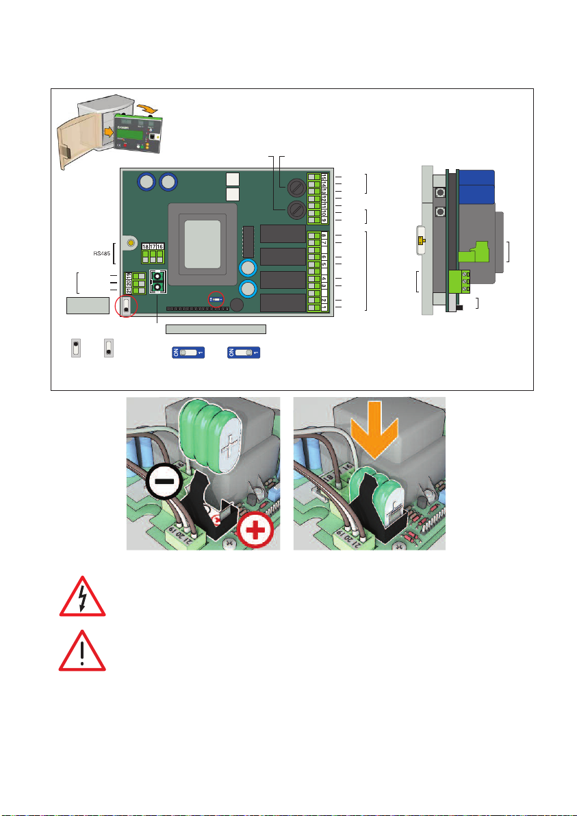
Back panel
To remove the electrical wiring base, turn it round and extract it from its housing.
Mixed outlet
sensors
Temperature
Thermal shock
activation
Shock
enabled
Common
Return
disabled
(factory setting)
Shock
Battery
–
+
Battery connected
Mixing valve fuse
1 A - 250 V delayed
Battery connection
Battery disconnected
Appliance fuse
400 mA-250Vdelayed
Closes
Common
Opens
Earth
Earth
Neutral
Live
Relay 4
Relay 3
Relay 2
Relay 1
PIN code
disabling button
valve
Mixing
Reset button
24 V
supply
Electric
Screw to close
the front cover
with hole
for lead-sealing
Temperature
sensor terminal
Relay contacts
PIN
disable
Reset
side view
Microswitch
for enabling
thermal shock
function
RS485
Interface
terminal
Connecting temperature sensors:
The cable connecting the mixed temperature outlet and return temperature sensors must be installed in a dedicated raceway. If the connection cable shares
the raceway with other live cables, an earthed shielded cable must be used.
In case of reverse polarity or power failure the system enters the BATTERY
ALARM STATUS, see “Alarms” section.
Buttons and terminals on side view
The base has two buttons, which can be accessed by opening the front cover:
-Reset button
-PIN code disabling button
9
Page 10
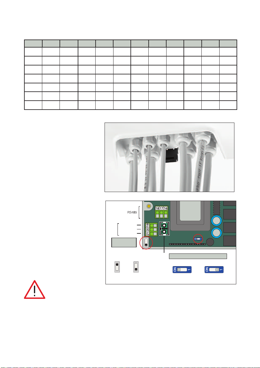
Temperature sensor resistance values
PIN
disable
Reset
Appliance fuse
400 mA-250Vdelayed
Mixing valve fuse
1 A - 250 V delayed
Relay contacts
Electric
supply
24 V
Mixing
valve
Relay 1
Relay 2
Relay 3
Relay 4
Closes
Common
Opens
Earth
Earth
Neutral
Live
PIN code
disabling button
Reset button
Screw to close
the front cover
with hole
for lead-sealing
Microswitch
for enabling
thermal shock
function
Temperature
sensor terminal
To remove the electrical wiring base, turn it round and extract it from its housing.
ºF ºC Ω ºF ºC Ω ºF ºC Ω ºF ºC Ω
-5 -20 100254 60 15 15310 130 54 3049 200 93 829
5 -15 72937 70 21 11882 140 60 2489 210 99 702
15 -10 53669 80 27 9297 150 65 2044 220 104 598
25 -4 39919 90 32 7333 160 71 1688 230 110 511
32 0 32648 100 38 5827 170 77 1402 240 115 439
40 4 26100 110 43 4664 180 82 1171 250 121 378
50 10 19900 120 49 3758 190 88 983
Location of cable connectors
When making the electrical
connections, follow this sequence
for wiring the terminal strip and
tightening the seals:
1. Power supply
2. Mixing valve control
3. Mixed outlet temperature sensor
7
5
4
3
1
2
9
6
8
4. Return temperature sensor
5. RS485
6. Relay 3
7. Relay 1
8. Relay 4
9. Relay 2
Strain relief cord connectors (white)
are provided for all 9 controller
housing holes. Clear plastic plugs
also provided for unused holes.
Enabling functionsDipswitch settings
-Thermal Shock enable/disable.
-Internal battery (do this during
installation)
ATTENTION: If the battery is not activated the battery alarm will be displayed.
CAUTION!
The controller is congured to automatically execute a daily rotation cycle to ensure efcient ball operation and cleaning. This occurs directly after the disinfection program, if
active, or after 24 hours have elapsed if disinfection is not active. Deactive this function
Mixed outlet
Common
sensors
Temperature
Thermal shock
activation
Shock
enabled
Return
Shock
disabled
(factory setting)
Battery
–
+
Battery connected
Battery connection
Battery disconnected
through the ANTI-CLOG setting by entering the release code 5566 and conrming with ON-
OFF. Eliminating this function increases the risk of deposits forming on moving parts of
valve. If it is necessary to eliminate the disinfection function as well, proceed as follows:
1. disable the ANTI-CLOG function; 2. eliminate the disinfection function.
10
Page 11
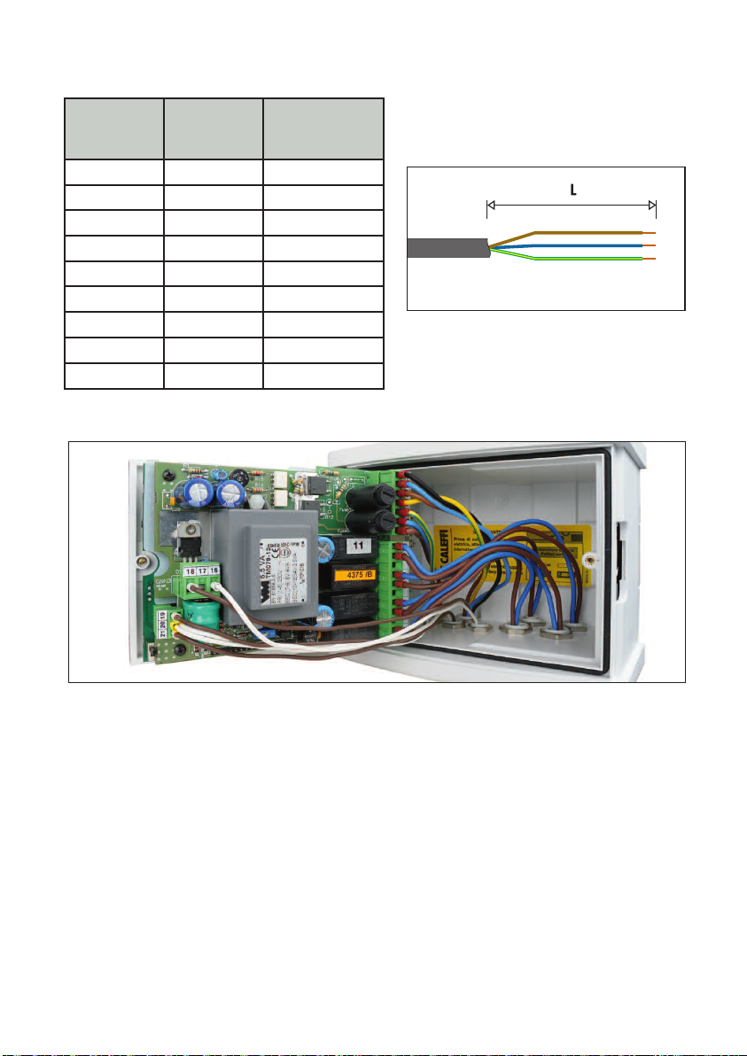
Connection cable cross-sections and lengths for circuit board wiring
Unsheathing
Cable seal No. Cable type
1 3 x AWG 16 5 / 130
2 6 x AWG 18 6 / 150
3 2 x AWG 18 8.25 / 210
4 2 x AWG 18 8.25 / 210
5 3 x AWG 18 8.25 / 210
6 2 x AWG 16 6.25 / 160
7 2 x AWG 16 6.25/ 160
8 2 x AWG 16 7 / 180
9 2 x AWG 16 6.25 / 160
(in/mm)
including stripping
(L)
Connection layout: connections must not create thrust stresses on the circuit board
11
Page 12
8 97
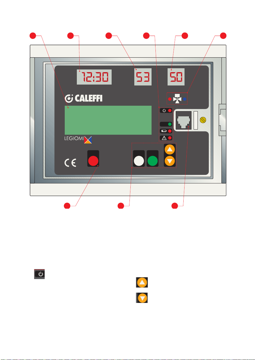
Front panel
1
Mixed °C Return ° C
THURSDAY 10/12/ 2017
M
T
127OF TR120OF
ADJUSTMENT
RUNNING
65432
Ok
OkMenuShock
Cut the wires of the auxiliary microswitch (if not used) and insulate electrically before
wiring (colors: white, green and red).
1. LCD display*
2. LED display: Time
3. LED display: Tmixed- Mixed Outlet
water temperature (°C only)
4. LED indicator
- ON
- Status OK
- Battery
- Alarm
*Tmixed and Treturn is displayed, default °F. Can be changed to °C in settings (Cels.-Fahr.)
5. LED display: Treturn - return water
(recirculation) temperature (°C only)
6. Mixing valve open/close LED
7. Thermal shock button
8. Navigation buttons
- Menu
- OK
- UP
- DOWN
9. RS 485 front connection
12
Page 13
Indication description
Return ˚C
Ok
Return ˚C
Ok
Return ˚C
TUESDAY
RUNNING
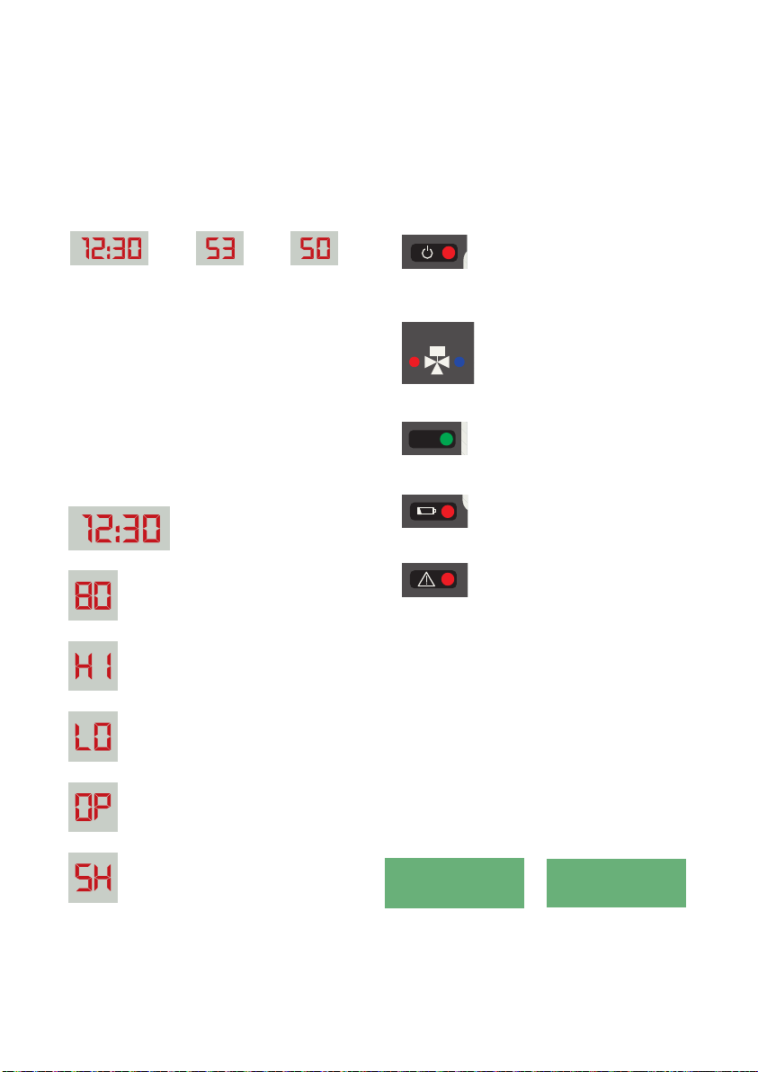
Indications on LED display
3 LED displays on the front of the controller
show the clock time and termperature of the
mixed outlet water temperature and return temperature sensors at all times.
Time
(24 hr clock)
Mixed
Outlet (°C)
Return
(Recirc) (°C)
The default setting for the temperatures is
OFF because the default temperature units
are ºF. If the units are changed to ºC, in the
configuration menu, these LEDs will read in
ºC. Also, if the recirculation sensor has been
set as “not present” in SETTINGS, or is faulty
in program 0, the related display remains
OFF. Temperatures are in ºC only, and can
not be changed to ºF.
Hour and minutes display
(24 hour system)
Sensor temperature
display (in ºC)
Resolution 1 ºC
Sensor warning display
“out of range” at top.
(blinking)
Sensor warning display
“out of range” at bottom.
(blinking)
Sensor warning display
“open”. (blinking)
Sensor warning display
“short circuit”. (blinking)
LED indicators
The following LED indicators are located on the front
of the controller:
Electric power supply LED:
red LED: steadily ON when
voltage is present.
Mixing valve LED:
Return ˚C
-red LED: on when opening
hot water.
-blue LED: on when opening
cold water.
Ok
Controller OK status LED: green
LED: steady ON when there are
no faults or active alarms.
Faulty battery LED:
red LED: on steady there is a
battery fault; otherwise it is Off.
Generic Alarm LED:
red LED: steadily ON when there
is an alarm (sensor fault, thermal
shock in progress, reset).
LCD indicators
Green backlit alphanumeric displays with 4 rows of
20 characters each, for setting parameters, scheduling operations, displaying error messages and machine status are on the front of the controller. Buttons
on the front panel (“MENU”, “UP”. “DOWN”, and
“OK”) can be used to scroll through the menu items
to configure the controller, set various parameters
and view the temperature log.
10/10/2017
M
T
127OF TR120OF
ADJUSTMENT
TUESDAY 1 / 02/ 2017
M
140OF TR135OF
T
DISINFECTION
RUNNING
13
Page 14

Operating status
n
w
,
C HE C K ON DIS IN FE C TI ON
Depending on the times and the programs that have been set, the controller may be in one of
the following operating modes.:
• Adjustment;
• Disinfection;
• Flushing;
• Thermal shock (this function has #1 priority over other modes)
In the event of trouble due to the LEGIOMIX or the system, the device manages and reports the
alarm and, depending on the situation, may maintain operation or not. Accordingly, a distinction
is made between the following:
• Active with alarm
• Inactive with alarm
The LEGIOMIX is equipped with a rechargeable battery that keeps the clock working and
maintains selected programmed settings during loss of power. In the event of blackout, to
ensure the longest battery life, the controller assumes the status:
• Inactive on Low Power
Adjustment (modulation)- default mode
LEGIOMIX measures the temperature of the mixed water at the valve outlet with temperature
sensor and adjusts (modulates) the mixing valve position to maintain the desired set temperature.
Disinfection
LEGIOMIX runs the disinfection phase, which consists of raising the water temperature to a preset value for a specific time duration, by operating the mixing valve as required.
Using the menu, set the days of the week for the disinfection phase to run.
At the end of disinfection, statistical data relating to the just concluded disinfection are logged.
This mode begins and ends automatically at a start time (Time ON) and end time (Time OFF)
that can be selected by the user in SETTINGS.
Safety measures must be in place before engaging disinfection mode. Anti-scald
protection devices, certied to ASSE 1016 or ASSE 1070, at all downstream xtures,
CONFIRMING DISINFECTION
Temp erature
t
1
SET2 - P R G1A
SET3 - P R G1B o r 2
tDIS= Σts> tM IN
Time ON Time OFF
NOTE: Graph is for reference only, not shown on display or logged data.
t
2
Time
14
Page 15

Conrming disinfection
If, within the time span (Time OFF - Time ON), the actual disinfection time reaches tDIS is greater than
the set tMIN, the disinfection is concluded with a positive outcome. It automatically exits this status
and returns to the adjustment (modulating) mode.
If the sufficient time tDIS is not reached, the disinfection phase ends at Time OFF.
Flushing
LEGIOMIX automatically enters this mode at the end of the disinfection phase, and is used to make
the water temperature return to the adjustment value (SET1 value) quicker, or to periodically clear (or
flush) the storage of impurities. This phase is ended after a time selected with the tFLUX parameter.
When flushing time has ended, relay 1, relay 4, and the controller returns to the “adjustment” mode.
Thermal shock
LEGIOMIX adjusts the mixed outlet water temperature at the set shock value (SETSH) for a selected
time duration (tSH). The Shock button on the front of the controller can be used then to initiate
thermal disinfection, the manual mode. This function is associated with activation of alarm 4 (AL4),
and illumination of the alarm LED. Thermal shock can be started by pressing the specific button on
the front panel (press and hold for at least 5 seconds) while the operating screen is displayed, or to
program it with the menu item for a delayed execution (countdown in minutes), or by remote control.
Thermal shock operation can be stopped, if needed, by pressing the shock button and
confirming with the “OK” button, or by remote control.
This is a potentially dangerous function so a jumper is provided on the printed circuit board to enable
it. If the jumper is closed, the Shock function can be used; if it is open, it is not available (see Back
Panel section).
At the end of the Thermal shock phase, the controller reverts to the “adjustment” (modulating) mode.
Low power
LEGIOMIX goes into low power mode with loss of power, and continues to run the internal date
clock. NOTE: in this condition there is no power for switching relays, so the controller does not
perform the adjustment or disinfection functions, sensor temperatures can not be acquired, and no
communication functionality is available. The mixing valve remains in the last state when power went
out. LCD and LED displays are off, all LEDs are off, except the “alarm” LED, which will be flashing.
When the power comes back on, the blackout is recorded in the log (alarm AL5) and the controller
returns to operating mode as programmed, unless the power failure lasts long enough to completely
run down the battery. In this case, LEGIOMIX will be reset to default values when the power is
restored.
In the event of a reset or extended power failure, factory settings are restored. If modifying the factory
settings, make a copy of the new settings.
ANTI-CLOG function
The LEGIOMIX controller is configured to execute a daily ball rotation cycle, to ensure efficient ball
operation and cleaning. This occurs after the disinfection program concludes, if active, or in any
case after 24 hours has elapsed when disinfection is not active. The ANTI-CLOG function can be
deactivated through the ANTI-CLOG step in the “SETTINGS” menu by entering the release code
5566 and confirming with ON-OFF. Eliminating this function increases the risk of deposits forming on
the moving parts of the valve.
If it is necessary to also eliminate the disinfection function, proceed in the following order: 1. eliminate
the ANTI-CLOG function, then 2. eliminate the disinfection function.
15
Page 16
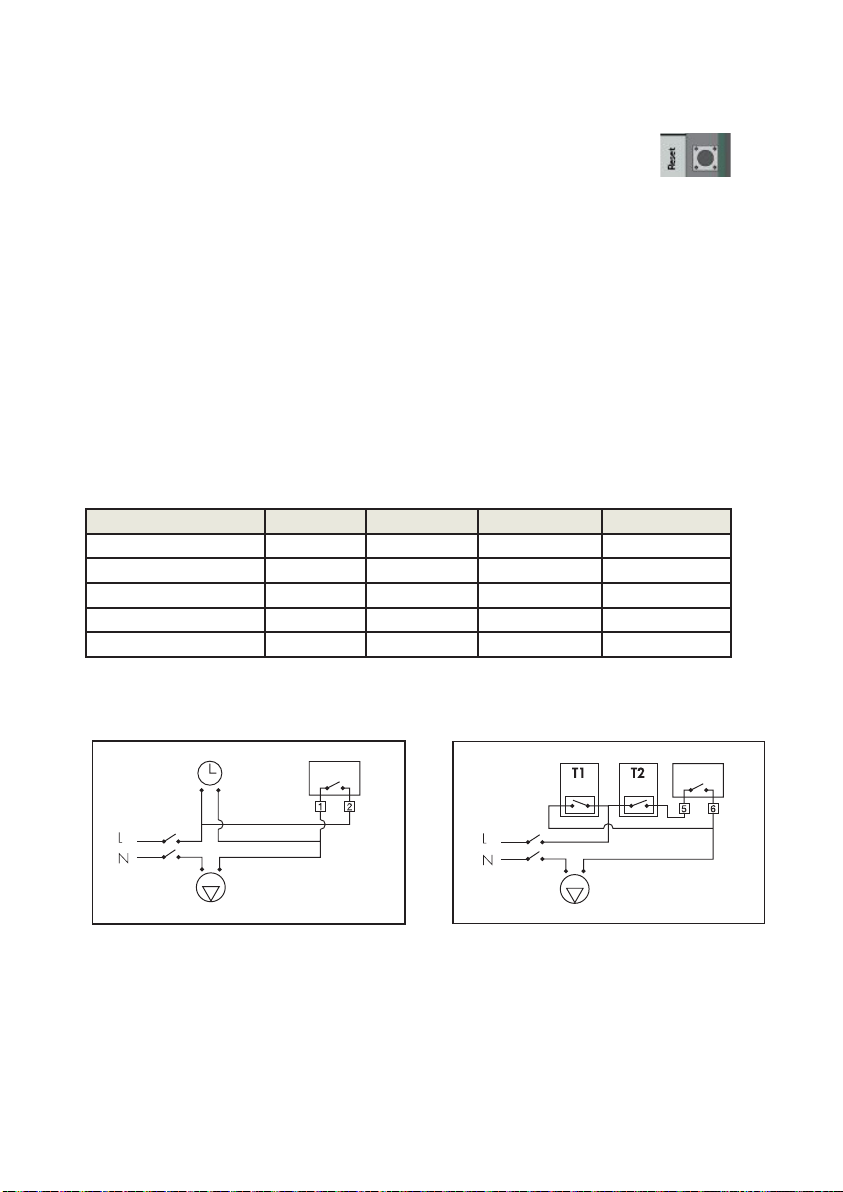
Reset
On the back panel, there is a specific reset button, in case it is necessary to retore the initial
settings.
If the date and time are not set after the reset, the controller will operate according to
the factory default settings.
Actuation relays
The circuit board and terminals show the relay contacts used to manage auxiliary equipment
and to report alarms.
• Relay 1: Circulation pump (active during disinfection) Connect Relay 1 in parallel to
time clock or aquastat contacts (whatever switch is controlling recirculation pump).
• Relay 2: Generic alarm (sensor fault, battery fault, blackout or clock failure).
• Relay 3: Second thermostat. Wire in parallel to High Temperature thermostat. Use to
increase hot water supply temperature for thermal disinfection.
• Relay 4: flushing valves
Summary of actuation relay status
Operating Status Adjustment Disinfection Flushing Thermal shock
Relay Contact status Contact status Contact status Contact status
Relay 1: recirc pump Open Closed Closed Closed
Relay 2: generic alarm Open Open Open Closed
Relay 3: second thermostat Open Cloase Open Closed
Relay 4: flush valves Open Open Closed Open
Wiring diagram of relay 1 with a clock for
managing the recirculation pump times.
Relay 1
Recirculation pump
Wiring diagram of relay 3 for connecting the
second thermostat on hot water storage.
140°F
160°F
Storage primary pump
16
Relay 3
Page 17

Programs
The operation of the controller during disinfection can be set according to different programs, selected
depending on the type of system and management of the system. Set the program, and the day and
time to turn on and turn off disinfection, in parameters in SETTINGS.
Program 0
Features continuous mixed outlet water temperature modulation with automatic disinfection in a time
band that can be set. Disinfection will run only when the Program Day (ProgDay) parameter has days
selected (default is no days) and the TimeOn and TimeOff parameters are filled in (default is 00:00 for
both). The return water temperature sensor is not used, but if present, it is used as a monitor only.
During the disinfection phase, the mixed outlet water temperature must remain above SET2 for a time
tDIS at least equal to tMIN, and if this occurs then disinfection has been successful. When this happens,
disinfection then stops. If disinfection is not successful, there is no alarm signal. If alarm indication for
unsuccessful disinfection is desired, use other programs.
Program 1A
Features continuous mixed outlet water temperature modulation with automatic disinfection in a time
band that can be set. Disinfection will run only when the Program Day (ProgDay) parameter has days
selected (default is no days) and the TimeOn and TimeOff parameters are filled in (default is 00:00 for
both). The return water temperature sensor is not used, but if present, it is used as a monitor only.
During the disinfection phase, the mixed outlet water temperature must remain above SET2 for a time
tDIS at least equal to tMIN, and if this occurs then disinfection has been successful. When this happens,
disinfection then stops. If the disinfection temperature is not reached or it cannot be maintained for a
sufficient period of time, the alarm for unsuccessful disinfection is generated. The alarm is recorded in
the log. The first time a button is pressed, the relay opens again. The other alarm indications are cleared
at the next successful disinfection.
Program 1B
This program can only be set if the return water temperature sensor is set at present. Identical to
the previous program (1A), the only difference is the successful outcome of the disinfection phase is
checked via the return water temperature sensor in relation to SET3 instead of via the mixed outlet
water temperature sensor in relation to SET2. As soon as conditions indicate successful disinfection,
disinfection then stops. If the disinfection temperature is not reached or it cannot be maintained fora
sufficient period of time, the alarm for unsuccessful disinfection is generated. The alarm is recorded in
the log. The first time a button is pressed, the relay opens again. The other alarm indications are cleared
at the next successful disinfection.
Program 2 (factory settings - default)
This program can only be set if the return water temperature sensor is used. By default, the disinfection
is not enabled (no days are selected). If days are selected during commissioning, it is identical to the
previous program (1B). The only difference is, if the return water temperature does not reach SET3
after a wait period (tWAIT) since the start of disinfection, the mixed outlet water temperature SET2 is
increased by a value equal to (SET3 - TR reached), considering that SET2 can not in any case exceed
the limit of SETMAX. This correction procedure (increasing only) of the disinfection SET is iterative: if
necessary, it is repeated in the time span defined by the TimeOn and TimeOff at each time interval
equal to tWAIT. As soon as conditions indicate successful disinfection, disinfection then stops. If the
disinfection temperature is not reached or it cannot be maintained for a sufficient period of time, the
alarm for unsuccessful disinfection is generated. The alarm is recorded in the log. The first time a
button is pressed, the relay opens again. The other alarm indications are cleared at the next successful
17
Page 18

Thermal disinfection
The temperatures and corresponding disinfection times for the network must be chosen according to
the type of system and the related intended use. The following criteria is generally followed, guided by.....
T = 160º F (70º C) for 10 minutes
T = 150º F (65º C) for 15 minutes
T = 140º F (60º C) for 30 minutes
Thermal disinfection is generally performed during times of reduced system usage, ie: nighttime. This
minimizes the potential for scald conditions to occur. Thermal disinfection is recommended to be run
every day and at least once per week.
Safety measures must be in place before engaging disinfection mode. Anti-scald protection
devices, certied to ASSE 1016 or ASSE 1070, at all downstream xtures, must be installed.
Interupting disinfection
Disinfection can be interupted while it is still in progress. On the working screen (showing the
message “disinfection in progress”), press the OK button once. The display shows the message “Cancel
disinfection?”; and at this point, the OK button can be pressed to stop the disinfection phase and return
to the adjustment function (without going through the flush phase). If the OK button is not pressed, after
a timeout of about 3 seconds, the display goes back to displaying the message “disinfection running”.
Table of thermal disinfection programs
Program # > 0 1A 1B 1B 2
type of
conrmation
Use of return
sensor
Return sensor
shown on LED
display
Adjustment
temperature
Disinfection
temperature
Alarm if
disinfection
unsuccessful
Recording in log
if disinfection
unsuccessful
Adjustment and
simple disinfection
without confirming
NO NO YES YES YES
As monitor only As monitor only YES YES YES
Flow*: (SET1)
68 - 185º F
Flow*: (SET2)
104 - 185º F
NONE YES YES YES YES
NONE YES YES YES YES
Adjustment
and disinfection
confirming on the
mixed outlet water
temperature
Flow*: (SET1)
68 - 185º F
Flow*: (SET2)
104 - 185º F
Adjustment and
disinfection check on
return temperature
to the central heating
system
Flow*: (SET1)
68 - 185º F
Recirculation: (SET3)
104 - 185º F
Continuous
disinfection
(max. 4 hours)
--
Recirculation:
(SET3)
104 - 185º F
- 24 hours
Adjustment
only (default).
If scheduled,
disinfection
confirming.
Flow*: (SET1)
68 - 185º F
Recirculation: (SET3)
104 - 185º F - with
adjustment of flow*
up to the max value
*mixed outlet water temperature
18
Page 19
Entering programs and settings
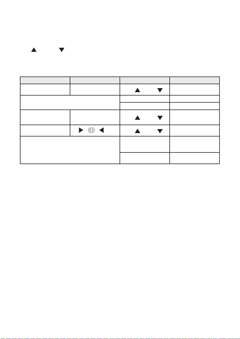
Controller operation is based on an internal clock with calendar and automatic time adjustment.
By navigating through the appropriate menu items and using the buttons on the front panel (“MENU”.
“UP” , “DOWN” , and “OK”), the user can configure the controller, set the various parameters,
and display the temperature log.
Functions of the conguration buttons
Description Display Button function Effect
Menu item - arrows beside
the row
Other rows available
-arrows in the screen margin
Parameter selection
-cursor flashing
“UP” , “DOWN”
+OK Opens the related submenue
Menu Go back to previous level
“UP” , “DOWN”
“UP” , “DOWN”
+OK
Menu
Moves the cursor to another
Increases or descreases the
Confirms the setting - cursor
row
Displays other rows in the
menu
parameter value
disappears and the value
becomes actual
Return to previous level
without making changes
Whatever status the controller is in (except Low Power), navigation around the various menus to read
the various settings and view the stored log data is always possible. However, for safety purposes, the
settings data can be modied only when the controller is in “Adjustment” mode. In particular,
parameters can not be modified while the controller is in “disinfection”, “flux” or “thermal shock” mode,
and when the controller is in the “inactive with alarm” status. The various options are made availalble,
depending on whether the return water temperature sensor has been enabled. To set programs 1B or
2, the return water temperature sensor must be set as Present. To be able to remove the return water
temperature sensor (i.e. set it as Present of Absent), program 0 or 1A must be set first.
Remote control
The controller can be controlled from a remote computer with the RS485 serial output connection, which
can be accessed by hard-wired terminals and through the connector on the front panel. Since the interface
is the multipoint bus type it is necessary for each controller connected on the bus to be identified by
an appropriate address to avoid identification conflicts. For a detailed description of the operations and
controls that are available from a remote location using this interface, refer to the relevant documentation.
Contact Caleffi for list of registers (points) for mapping LEGIOMIX information to ModBus. Configuation,
mapping, hardware (routers, modem, etc.), and software are customer/user responsibility. Code NA10520
Modbus-to-BACnet gateway is available separately for translating ModBus to BACnet.
19
Page 20
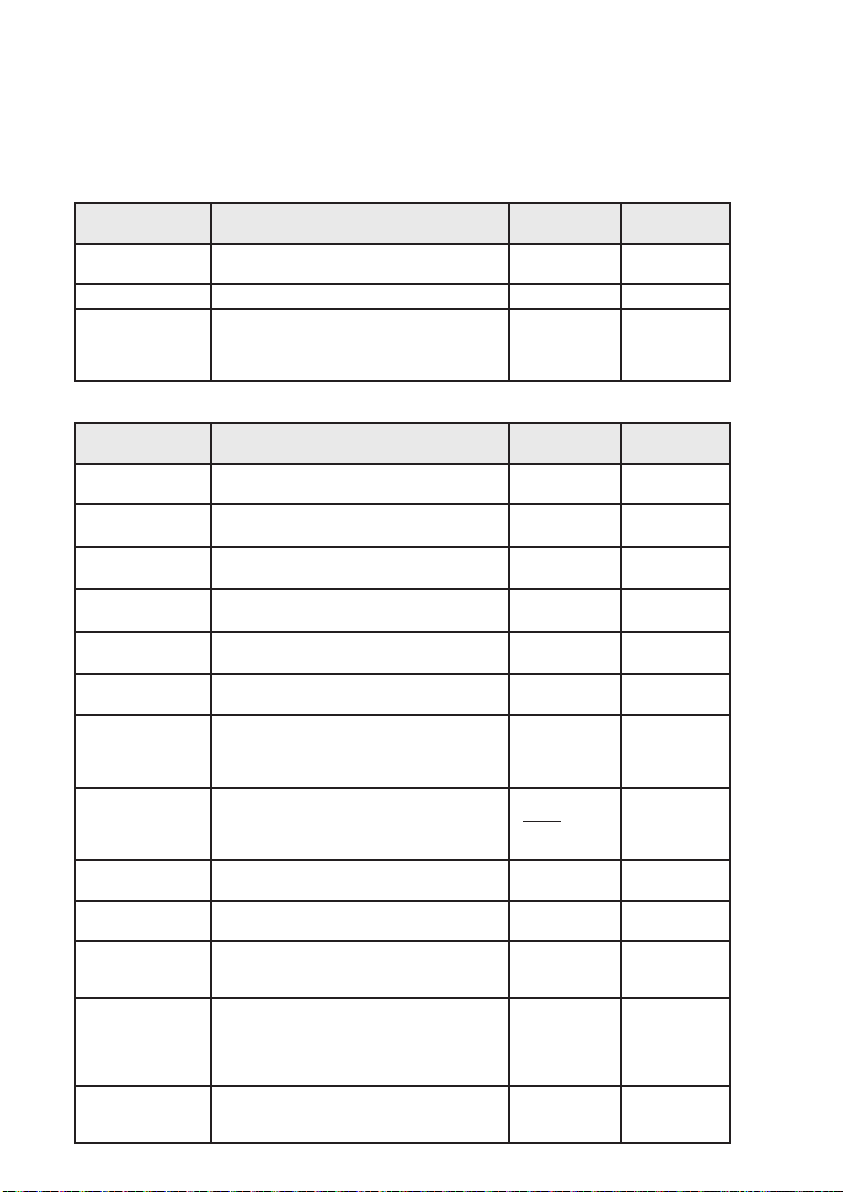
Operating parameters
The operating parameters can be set in the appropriate menus, and are summarized below:
Summary of parameters. Setting ranges and factory (default) conguration.
Parameter Description Setting Range
Language Language shown on LCD display
Date/Time For Disinfection phase and log entries MM/DD/YY 01/01/2005
Time change Daylight saving time setting
I-E-F-D-ES-P-NLSL-HR-SR-RO
USA
CUS.
NO
EUR
Factory (default)
conguration
ENGLISH
USA
Settings
Parameter Description Setting Range
LEGIOMIX “BUS iID”
SET_MAX
SET1
SET2
SET3
Return sensor present
(Rec probe)
PGM program
ProgDay
TIME ON Start time for the programmed disinfection.
TIME OFF End time for the programmed disinfection.
tWAIT
tMIN
tFLUX
Number that identifies this appliance (device) among
those connected to the BUS.
Sets the max temperature limit: to protect the system.
None of the SET values can exceed SET MAX.
Setpoint for Ta (mixed outlet temperature) during
adjustment phase.
Setpoint for Ta (mixed outlet temperature) during
disinfection phase.
Setpoint for Ta (return temperature) during disinfection
phase, for programs 1B or 2.
The return sensor is analog (NTC).
To modify the working parameters for the disinfection
phase.
Disinfection is conducted on the selected days. Day
1 is Monday.
Represents the time considered necessary for the
system to bring the return water to a temperature
above SET3.
The minimum time for the temperature measured by
the mixed outlet water temperature sensor (program
1A) or the return water temperature sensor (programs
1B or 2) must remain above the disinfection setpoint
so that disinfection will be completed successfully.
Duration of the flushing phase that will start automatically when a disinfection phase is completed.
0 to 255 001
122 - 194°F
50 - 90°C
68 - 185°F
20 - 85°C
104 - 185°F
40 - 85°C
104 - 185°F
40 - 85°C
NO=absent
YES=present
PRGM 0=0
PRGM 1A=1A
PRGM=1B=2B
PRGM 2=2
1 2 3 4 5 6 7 or
BLANK for each
digit to disable
disinfection
HHMM
0000-2359
HHMM
0000-2359
1 to 255 min 002 min
0 to 254 min (max
4 hour 14 min)
from 0 to 2550
sec in 10 sec
steps
Factory (default)
conguration
149°F
113°F
140°F
135°F
YES
2
No days selected
0200
0300
030 min
000 sec
20
Page 21

Parameter Description Setting Range
tPLAY
tMOTOR
ANTI-CLOG
Cels.-Fahr. Temperature units.
Delay due to gap in mechanical components during
actuator movement, until the internal valve ball starts
to move in the opposite direction.
Time required for the actuator to move the valve from
the full closed to the fully open position. Default setting
is recommended for all applications, do not change.
Consult Caleffi otherwise. (This is NOT motor stroke
time)
Ball rotation cycle to clean deposit formation for
efficient operation. To deactivate enter release code
5566 and confirm with ON-OFF.
from 0 to 255 sec
in 1 sec steps
from 8 to 320 sec
in 2 sec steps
ON
OFF
°F
°C
Factory (default)
conguration
005 sec
100 sec
ON
°F
Thermal shock
Parameter Description Setting Range Factory (default)
SETSH
tSH
Countdown Countdown before activating thermal shock 0 to 999 min 0001 min
Activate countdown Enables activation of countdown before thermal shock
Setpoint for Ta (mixed outlet water temperature) during
shock phase.
Duration of thermal shock phase to be started manually by the user
86 - 185°F
30 - 85°C
1 to 4320 min 005 min
NO= not active
YES= active
conguration
140°F
NONE
Temperature History
Temperat. History, read only. See Log section, next.
21
Page 22

Log
But t ons Lock
But t ons Lock
RUNNING
The “log” is a FIFO (First In - First Out, loop buffer) that is continually updated and records parameters
relating to adjustment and disinfection phases that occurred during the day. Data are stored for the
last 40 days, after which the data for the first day are overwritten, etc.
The hourly average mixed outlet and return water termperatures are save to Eeprom every hour, and
alarms are saved at the time they occur. The average hourly values of the current day can be viewed
at any time. The disinfection data are saved when disinfection ends. The log (via specific menu item)
can be viewed on the display or remotely via the RS485 serial interface.
The parameters saved in the log are:
-Date (day, month, year)
-Set program. This is saved when disinfection starts.
-tDIS: actual disinfection time (in steps of minutes).
When the set program is 0 or 1A, this parameter is the time when the temperature of the mixed outlet
water was above SET2.
When the set program is 1B or 2, this parameter is the time when the temperature of the return water
was above SET3.
This is helpful when it is less than tMIN, to understand how much greater the span of TIME ON: TIME
OFF should be to complete the disinfection.
-TRMAX: Max. temperature of the return water sensor during disinfection (if a disinfection was completed
that day).
-TRMIN: Min. temperature of the return water sensor duriong disinfection (if a disinfection was completed that day). It is calculated from the time when the return water sensor measured a value greater
than SET3, beginning from the time when the disinfection starts being effective.
-ALARMS AL1, AL2, AL3, AL4, AL5, AL6, AL7 if they were activated on the day in question.
-24 hourly average values of the mixed outlet water temperature.
-24 hourly average values of the return water temperature.
If no disinfection was completed on that day, then the related fields will contain a default value.
If there have been any faults in one or both sensors, the hourly average data will be represented by
dashes. If there are any gaps or unavailable data due to a change of date, time, etc., the cells will
contain a default value and will be represented on the display by dashes.
Keyboard Lock (Access PIN code)
Menu navigation can be prevented by enabling the keypad lock function. The keypad is
then unlocked by entering a PIN code. If the lock function is enabled, the keypad is locked
automatically after a timeout of 10 minutes starting from the last button press. When the
keypad lock function is active, a padlock symbol appears on the LCD working screen (on the right).
Also, if the lock function is active and a button is pressed while the working screen is displayed, the PIN
code input screen appears: The code is entered by selecting the first digit using the “UP” and “DOWN”
buttons, then confirming by pressing OK. The second digit is entered in the same way, etc.
Tuesday 12/ 06/ 2016
TM127OF TR120OF
ADJUSTMENT
When the last digit is confirmed, if the code is correct, the user can access the menus; if the code is
incorrect, the PIN entry screen appears again. If the timeout elapses, the display shows the working
screen again.
If the PIN code is lost or misplaced, the lock function can be overridden (the PIN code is
forced to 0000) by pressing a button on the back of the panel (for 5 sec), or by sending a
special command through the RS485 interface.
PIN 0000
CONFIRM NO
PIN 2600
CONFIRM NO
22
Page 23

Deleting the Log
HISTORIC 06/ 04/ 2005
HISTORIC 06/ 04/ 2005
HISTORIC 06/ 04/ 2005
t DIS 060’ PGRM 1A
R
MAX 130° TR MIN 120 °
T
ALARM -- -4 5-7-
The log can be completely erased from the non-volatile memory, using this procdure:
Select the “temperat.history” menu item and press the OK button.
The display shows the data from the first log record available.
Now press and hold the Shock button for at least 1 second.
The display shows a blank screen, which is then gradually filled, indicating that the delete operation is
in progress; the LCD display then shows the menu selection screen (higher level), and the log has been
completely erased.
If you now go into the log submenu, the only record available will be the one for the present day; note
that the temperatures for all hours previous to the present one have also been deleted.
IMPORTANT: once initiated, the delete operation cannot be cancelled.
Battery
The controller has an integrated rechargeable battery (three 140 mAh cells), used to keep the internal
clock running and maintain the selected settings even if there is a power failure. While in operation,
the battery level of charge is checked periodically (about avery 24 h ours), and the recharge function is
activated if neeeded. When the battery recharge function is active, the “Btr” icon appears in the working
window (in the adjustment mode).
H 001 002 003 004
TM --- --- --- ---
R
--- --- --- ---
T
H 007 008 009 010
M
120 120 120 122
T
TR 116 116 116 116
Tuesday 12/ 06/ 2016 Tuesday 12/ 06/ 2016
M
127OF TR120OF
TM127OF TR120OF
ADJUSTMENT
RUNNING
T
BATTERY
ALARM
Battery charging Battery fault
If the parameter readings are not within the specified range, the battery is damaged and must be
replaced. If a battery fault is detected, the corresponding alarm appears (see the Alarms section):
In principle, a battery fault should not affect any of the controller functions, unless there is also a power
supply failure.
Battery replacment
When necessary, replace the battery by removing the depleted battery from its seat and inserting the
new battery per the correct polarity placement, shown in the figure.
–
+
23
Page 24

L e ve l 1 L e ve l 2 L e ve l 3 B u tt on fu nc t io ns
Menu structure table
L A NG U A G E S E L L A NG U A G E S E L
DA T E /T IM E D AT E /T I ME
S E T T I N G S E T T I N G
T H E R M AL S H O C K T H E R M AL S H O C K
I - E - F - D - E S - P - NL - UP D OWN + OK
Conrm the language when turning on the controller. If the language is not selected after 1 minute, the menu
goes directly to the date and time selection step. Use the “setting” menu to select language any time.
S L - H R - S R - RO
DAT E 01 -0 1-2 00 5 S et : da y/m ont h/y ea r UP D OWN + OK
T IM E 00: 00 S e t: ti me UP D OWN + OK
T IM E A DJ US T M EN T USA USA - CUS. - NO - EUR UP D OWN + OK
B us ID 001 f rom 0 to 25 5 U P DO WN + O K
S E T M AX 50 °C to 9 0° C UP D OWN + OK
S E T1 2 0 °C t o 85 °C U P DO WN + O K
S E T2 40 °C to 85 °C UP DO WN + O K
S E T3 UP D OWN + OK
R ec pr obe YES N O - YE S UP D OWN + OK
P R GM 2 0 - 1A - 1 B - 2 UP D OWN + OK
P rog .da y
T ime ON 02: 00 S e t tim e UP DO WN + OK
T ime OF F 0 3:00 S e t tim e UP DO WN + O K
tW AIT 00 2’ 1 t o 2 5 5 min ute s U P DO WN + O K
tM IN 030‘ 0 to 25 4 mi nut es UP DO WN + O K
tF LU X 000 0‘ fr om 0 to 2 55 0 s ec on ds UP DO WN + O K
tP L AY 005 ‘ f rom 1 to 25 5 s ec on ds U P DO WN + O K
tM OT OR 1 00‘ 8 t o 32 0 s ec ond s UP DO WN + O K
AN TI C LO G
S E TS H UP D OWN + OK
tS H 005’ f rom 1 to 43 20 min ute s UP D OWN + OK
C OU NT DO WN 00 1’ 0 t o 99 9 mi nut es UP DOW N + O K
AC T IVAT E co unt dow n NO NO - YE S UP DO WN + OK
149°F
113°F
140°F
135°F
_ _ _ _ _ _ _
ON ON - OF F (se e ins truc t. pa ge 14) U P DO WN + O K
140°F
122°F to 194°F /
68°F to 185°F /
104°F to 185°F /
104°F to 185°F /
S el ec t day(s) 1 2 3 4 5 6 7 OK
85°F to 185°F /
40 °C to 85 °C
30 °C to 85 °C
HISTORIC . V I E W T E MP E R A T UR E
T E M P E R AT U R E
MM/D D / YY UP-DOWN
K E Y P A D L O C K K E Y P A D L OC K
P IN 0 000 S el ec t c ode U P DO WN + O K
E NA BL E NO NO - Y E S UP DO WN + O K
L OG MM/D D / YY (Example)
tD IS 06 0’
P R GM 2
T R M AX
136°F
120°F
T R M IN
AL AR M 123 4567
h 0 1
02 03 02 4
TA 105 110 95 115
T R 100 105 90 110
24
UP D OWN + OK
Page 25

Operability after alarm (page 1)
Type of alar m P rog ram In dic ation by ala rm L ED I ndic ation by LE D d ispla y Di spla y o n L CD R eco rding in lo g
AL 1: f low probe
fau lty
R eturn pro be f ault
AL 2: r eturn pro be
fau lt
Dis infec tion not
co mplete d
AL 3: d isin fec tion
not com plete d
0 1 A 1B 2 Ge neric alarm L ED comes
0 1 A The alarm L ED remains Off
1B 2 G eneric alarm LED come s
0 The alarm LE D rema ins O ff
1A 1B 2 “G eneric ala rm” LE D c omes
On and S tatus O K LE D goe s
Off.
and the “S tatus OK ” LE D
remains On.
On and S tatus O K LE D goe s
Off.
and the “S tatus OK ” LE D
remains On.
On and “S tatus O K” LE D
goes Off.
Alarm shown on L ED disp lay.
(“HI , “L O”, “SH ”, “OP”
depe nding on c as e).
Re mains Off if prog ram 0,
and “HI, “LO ”, “ SH”, “O P”
disp layed (depend ing on
ca se) if progra m is 1A.
Alarm shown on L ED disp lay.
(“HI , “L O”, “SH ”, “OP”
depe nding on c as e).
NON E NON E N ONE
NON E “Dis infection incomplete”
“Flow p robe fault” a larm
disp layed on LC D.
NON E F ault is recorde d in the day
“R eturn probe fault” alarm on
LC D ( sc reen a lte rnates with
working s cree n).
alarm on LC D (sc reen
alternates with the working
sc reen).
YE S (AL1) S tored in the da y
log.
log.
YE S (AL2) S tored in the da y
log.
YE S (AL3) S tored in the da y
log.
AL 4: t herma l
sh ock in prog res s
AL 5: b lac kout
(ma ins powe r
failu re)
AL 6: a pplia nce
res et
AL 7: b atter y
dam age d
0 1 A 1B 2 Ge neric alarm c omes On
0 1 A 1B 2 The indicator L EDs rema in
0 1 A 1B 2 Ge neric alarm L ED comes
0 1 A 1B 2 “OK s tatus” L ED goes Off.
(but, if no other faults, the
Status OK L ED also remains
On).
Off. Only the generic alarm
flashe s.
On and “O K status” LE D O ff.
“B TR FAIL ” LE D comes On.
(The generic ala rm LE D is
not lit).
NON E “Therma l shoc k in p rogress ”
Tempe rature indica tors a nd
cloc k rema in Off.
Tempe ratures are not
ac quired.
Time display 00 : 00 blinking.
Time on the LC D.
NON E “B attery damage d” a ppears
alarm on the L CD displa y.
LC D re mains Off. R ecord ing of log data is
Entering sc reen dis played
Date and jus t set
Disp laying of 0 1/01/2005 in
the LC D date field.
on L CD displa y (a lte rnating
with the working s cree n).
YE S (AL4) S tored in the da y
log.
sus pended .
YE S (AL5) When power is
restored it is stored in the log.
YE S (AL6) S tored in the da y
log.
YE S (AL7) S tored in the da y
log.
25
Page 26

Operability after alarm (page 2)
R elay s tatus O pera ting sta tus
Re lay 2 clos ed ( if no ala rms,
the relay is normally open) .
Re lay 2 open.
The alarm re lay doe s not
cha nge s tatus.
Re lay 2 clos ed.
(if no alarms, the rela y is
normally ope n).
Re lay 2 open.
The alarm re lay doe s not
cha nge s tatus.
Re lay 2 clos ed.
(if no alarms, the rela y is
normally ope n).
Re lay 2 clos ed.
(if no alarms, the rela y is
normally ope n).
Re lay 2 clos ed.
(if no alarms, the rela y is
normally ope n).
No relay action.
Re lay 2 open.
The alarm re lay doe s not
cha nge s tatus.
In s afe mode. Mixing valve clos es, i.e. only c old water enters.
Adjus tment or d isinfection or thermal shoc k is ca ncelled .
All a larm indica tions are cleare d when the ca use of the ala rm has bee n removed.
All functions are ensured .
The return probe, if pres ent, is us ed a s a monitor only, since it does not gene rate an alarm if faulty.
No d isinfection, but adjus tment c ontinues and thermal shock is poss ible.
When the firs t button is pres sed , the relay re -opens; indica tion rema ins on the disp lay.
In a ll ca ses , a ll alarm indications are c leared when the caus e of the alarm has been removed.
Disinfec tion failure doe s not g enerate any a larms.
When the firs t button is pres sed , the relay re -opens; indica tion rema ins on the disp lay.
In a ll ca ses , a ll alarm indications are c leared when the caus e of the alarm has been removed, in this cas e when the next dis infection
is succ es sfully c ompleted.
Note: if program 0 is se t, any unresolved alarm indication d ue to incomp lete disinfec tion is c leared .
Alarms gene rated. The thermal shoc k function is potentially da ngerous for users of the s ystem.
When the firs t button is pres sed , the relay re -opens; indica tion rema ins on the disp lay.
In a ll ca ses , a ll alarm indications are c leared when the caus e of the alarm has been removed, in in this ca se when the s hock func tion
has ended and the ap pliance begins adjus tment a gain.
If there is a mains power failure, the bac k-up ba tte ry kee ps the applianc e’s internal clock running.
In this situation, a ll actuations are inhibite d (the relays ca nnot be opera ted), and therefore all the adjustment, d isinfection a nd thermal
shoc k progra ms. In this status, the ap pliance goes into Low Power mode in orde r to ens ure maximum autonomy.
The RS 485 inte rface is not available .
When power is res
programs ; there are no ala rm indica tions.
However, if the mains p ower failure lasts long enough for the ba tte ry to bec ome d ischa rged, there is a genera l rese t when power is
restored .
The printed c ircuit board has a button for hardwa re res et of the applianc e. This b utton ca nnot be op erated from the front panel, but
only by opening the door of the a pplianc e and ac ces sing the printed c ircuit boa rd.
If the applianc e is res et ac cidentally, or intentionally by press ing the s pec ial hidde n button, or by interference (lightning, e tc.), the
correc t time and date settings are lost.
Se ttings
made by the user are also lost, a nd the fa ctory values a re reloa ded for all pa rameters and settings.
Therefore, until the c orrect d ate and time are re-entered :
Applianc e re mains active in adjustment mode .
Disinfec tion is inhibited.
Thermal shoc k progra m is inhibite d (b ut thermal shoc k c an s till be force d manua lly or remotely).
When the c urrent da te and time have b een s et (manua lly or remotely), the d ev
normal ope ration. All a larm indic ations a re c leared.
While in operation, the level of c harge in the b attery is chec ked periodica lly (ab out eve ry 24 h), and the recha rge func tion is
ac tivated if nece ss ary. If the pa rameter re adings are not within the s pec ified rang e, it me ans the battery is da maged and must be
replac ed.
However, the a ppliance continues performing the s pec ified progra ms, sinc e a battery fault d oes not affect a ny of the applianc e
functions
(unless there is a blac kout).
NOT E: for the b attery replac ement opera tion refer to the proc edure desc ribed on pag e 20 .
tored, the blackout a larm (A L5) is s tored in the log , and the a ppliance res umes op eration as de fined in the
ice comes out of the a larm c ondition and re sumes
26
Page 27
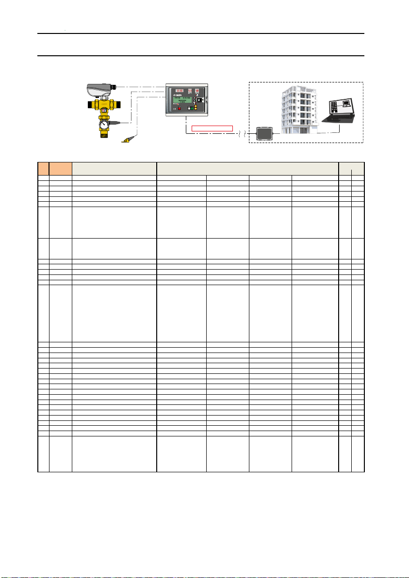
MODBUS Registers LEGIOMIX
0x03 0x06
x
1 0001 BUS address 1…247 x
2 0002 T mix (°C) x
x
4 0004 T mix (°F) x
1= regulation
3= ushing
4= thermal shock
x x
2= Program 1B
3= Program 2
x x
9 0009 MONTH 1…12 x x
10 000A YEAR 2017… x x
x x
13 000D LANGUAGE 0= IT x x
1= EN
2= FR
4= ES
7= SL
8= HR
9= SR
10= RO
x x
x x
x x
18 0012 TIME wait (time read ing recirc. Temp.) 1…255 (min) x x
19 0013 TIME min (MINIMUM DISINFECTION TIME) 0…254 (min) x x
20 0014 TIME ux (after ending the disinfection) 0…2550 (sec) x x
21 0015 TIME shock (time of duration shock) 1…4320 (min) x x
22 0016 SET REG - mixing regulation set temperature 20…85 (°C) x x
x x
26 001A SET Tmax - Maximum limit of range set temperature 50…90 (°C) x x
27 001B SET REG - mixing regulation set temperature 68…185 (°F) x x
28 001C SET DIS - disinfection set temperature 104…185 (°F) x x
29 001D SET REC - recirculation set temperature 104…185 (°F) x x
32 0020 Daily disinfection 0= Monday x x
2= Wednesday
3= Thursday
4= Friday
6= Sunday
H0002995
www.cale.com
®
40
60
20
80
0
°
C
RS485/MODBUS-RTU
VALUEREG (hex) DESCRIPTIONREG
0 0000 Product type Code to dene the product 6001
3 0003 T rec (°C)
5 0005 T rec (°F) x
6 0006 STATUS 0= - x
2= disinfection
7 0007 PROGRAM 0= Program 0
8 0008 DAY 1…31
11 000B HOUR 0…23
12 000C MINUTE 0…59 x x
14 000E TIME ON - h (Disinfection start hour) 0…23
15 000F TIME ON - min (Disinfection start minute) 0…59
16 0010 TIME OFF - h (Disinfection stop hour) 0…23 x x
17 0011 TIME OFF - min (Disinfection stop minute) 0…59
23 0017 SET DIS - disinfection set temperature 40…85 (°C) x x
24 0018 SET REC - recirculation set temperature 40…85 (°C) x x
25 0019 SET SHOCK - shock set temperature 30…85 (°C)
5= alarm
1= Program 1A
3= DE
5= P
6= NL
BMS
FUNCTION
30 001E SET SHOCK - shock set temperature 86…185 (°F) x x
31 001F SET Tmax - Maximum limit of range set temperature 122…194 (°F) x x
1= Tuesday
5= Saturday
27
Page 28
0x03 0x06
4= Friday
5= Saturday
6= Sunday
33 0021 Active functions b0: Presence of recirc. probe x x
b1: Anticlog
b2:0 b3:0 = Legal hour OFF b2:1 b3:0 = Legal hour EU b2:0 b3:1 = Legal hour US b2:1 b3:1 = Legal hour CUST
-
b5: LED display enable
34 0022 Forced activities 0= Shock activation x
1= Pin-code reset
2= Disinfection reset
3= Alarm reset
36 0024 TIME play - delay of time of actuator 1…255 (sec) x x
37 0025 START Sunday legal hour -3…3 x x
38 0026 START Month legal hour 1…12 x x
x x
40 0028 END Month legal hour 1…12
x x
4, month = 4 rejected if day = 31).
b4: Internatiol System of Unit
VALUEREG (hex) DESCRIPTIONREG
FUNCTION
35 0023 TIME motor - from close to full open 8…320 (sec) x x
39 0027 END Sunday legal hour -3…3
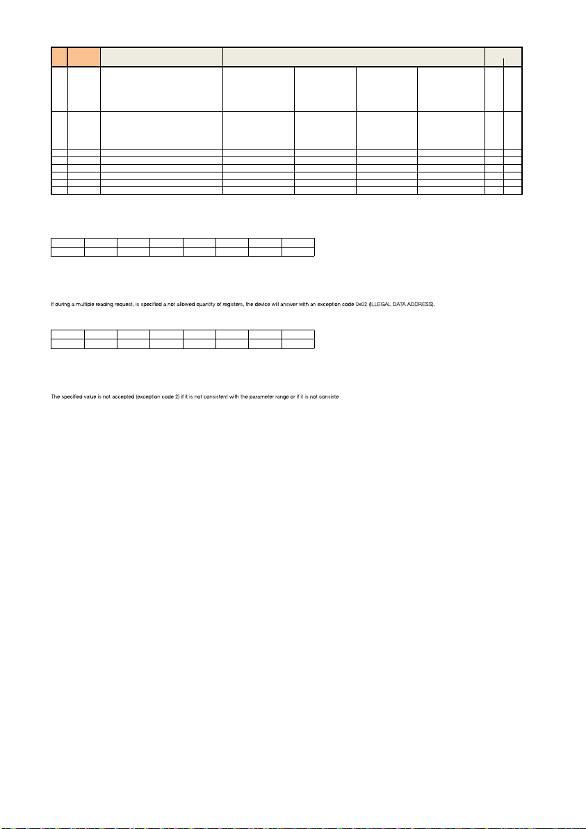
MODBUS functions:
Function 0x03 - Read Holding Registers
Used to read one or more parameters (the size of every parameter is 16 bit)
The frame has the following structure:
dev. Addr. func start addr H start addr L N.regs H N.regs L CRC16H CRC16L
HH 03 HH HH 00 HH HH HH
dev. Addr. – Address of the device on the RS485 net (1-247)
Func – Function code = 3
start addr H - MSByte of the address of the parameter:
start addr L - LSByte of the address of the parameter
N.regs H - MSByte of the number of registers to read (always 0)
N.regs L - LSByte of the number of registers to read
CRC16H - MSByte of CRC16
CRC16L - LSByte of
Function 0x06 - Write Single Register
Used to write a single parameter ( 16 bit )
The frame has the following structure:
dev. Addr. func Reg.addr H Reg.addr L Reg. val. H Reg. val. L CRC16H CRC16L
HH 06 HH HH HH HH HH HH
dev. Addr. - Address of the device on the RS485 net (1-247)
Func - Function code = 6
Reg. addr H - MSByte of the address of the parameter
Reg addr L - LSByte of the address of the parameter
Reg. val. H - MSByte of the value of the parameter
Reg val. L - LSByte of the value of the parameter
CRC16H - MSByte of CRC16
CRC16L - LSByte of CRC16
CRC16
4= Historical data reset
nt with the current state of the device (e.g. day = 31 rejected if month =
28
Page 29

Plumbing installation
∞
∞
∞
Before installing the LEGIOMIX electronic mixing valve, pipes must be flushed to prevent impurities in
the water from affecting performance. Always install strainers of appropriately sized capacity at the inlet
from the water main supply. Caleffi LEGIOMIX electronic mixing valves must be installed as shown below, conforming to applicable codes, and installed either vertically or horizontally, but the actuator must
never be oriented upside down.
System piping
Recirculation connections in hot water system should be located as near as possible to the fixtures they
serve.
Anti-scald mixing valves should be located at all points of use (i.e. sinks) to provide safe water temperature as specified in local codes or requirements.
All mixing valves should be identified and have their maximum discharge temperature measured and
documented on regular basis.
Where a mixing valve is installed within the hot water supply;
a) Precaution should be taken to prevent the buildup of high temperature water in piping during periods
of low or no use.
b) Check valves should be provided to prevent bypassing of hot and cold water through the mixing
valve.
The mixing valve body indicates with arrows, hot water inlet- red, cold water inlet - blue.
∞
∞
∞
Check valve
In systems with inlet pressure fluctuations, check valves should be installed to prevent backflows, as
is shown in the application diagrams. Check valves, code NA10366 (for 1” and 1¼” LEGIOMIX) and
NA10367 (for 1½” and 2” LEGIOMIX) may be used.
Commissioning
Due to the special purpose for electronic mixing valves, commissioning in accordance with current
regulations and by qualified personnel using suitable instruments is required. Check that the hot and
cold water supply pressures are within operating limits of the mixing valve, see technical specifications.
Check the temperature of the hot water coming from storage, greater than or equal to 140°F (60°C).
Record all parameters settings and measurements taken in the installation log book.
29
Page 30

TUESDAY
03/ 02/ 2006 TUESDAY 03/ 02/ 2006 TUESDAY 03/ 02/ 2006
Maintenance
During service, regularly monitor the performance of the LEGIOMIX electronic mixing valve since any
loss of performance may indicate maintenance is needed for the valve or the system. If the temperature
of the mixed water is found the have changed significantly compared to previous recordings, refer to
installation and commissioning sections. The following check points are recommended periodically, at
least every 12 months or more frequently, to ensure that the valve continues to deliver optimum levels
of performance:
1) Check and clean the filters installed in the system.
2) Check that any check valve installed at the inlet of the LEGIOMIX electronic mixing valve is functioning
correctly, and there are no leaks caused by dirt.
3) The internal components of the valve can be descaled by immersing in a suitable descaling fluid.
4) Follow commissioning procedure again after maintainable components have been checked.
5) Record all operations conducted on system log book.
Alarm management
To make it easier to resolve any functional faults that occur after installation and commissioning, the
controller is configured so that faults are indicated by special alarms and the appropriate action is taken.
The cause of the alarm is shown on the LCD display. If the alarm does not inhibit all the functions, the
alarm screen will alternate with controller status screen.
Alarm description
Alarm indicator Description
AL1 Mixed outlet water
AL2 Return water temperature
AL3 Disinfection failed
AL4 Thermal shock in progress
AL5 Main power failure
AL6 Controller reset
AL7 Battery default
MIXING PROBE
ALARM
RECIRCULATION
PROBE ALARM
ALARM
DISINFECTION
INCOMPLETE
TUESDA Y 03/ 02/ 2006
BATTERY PROBE
ALARM
Depending on the alarm type, certain actions occur,
relay statuses modified and information shown on
temperature sensor fault
sensor fault
the LED display, LCD display and LEDs on the front
panel.
30
Page 31
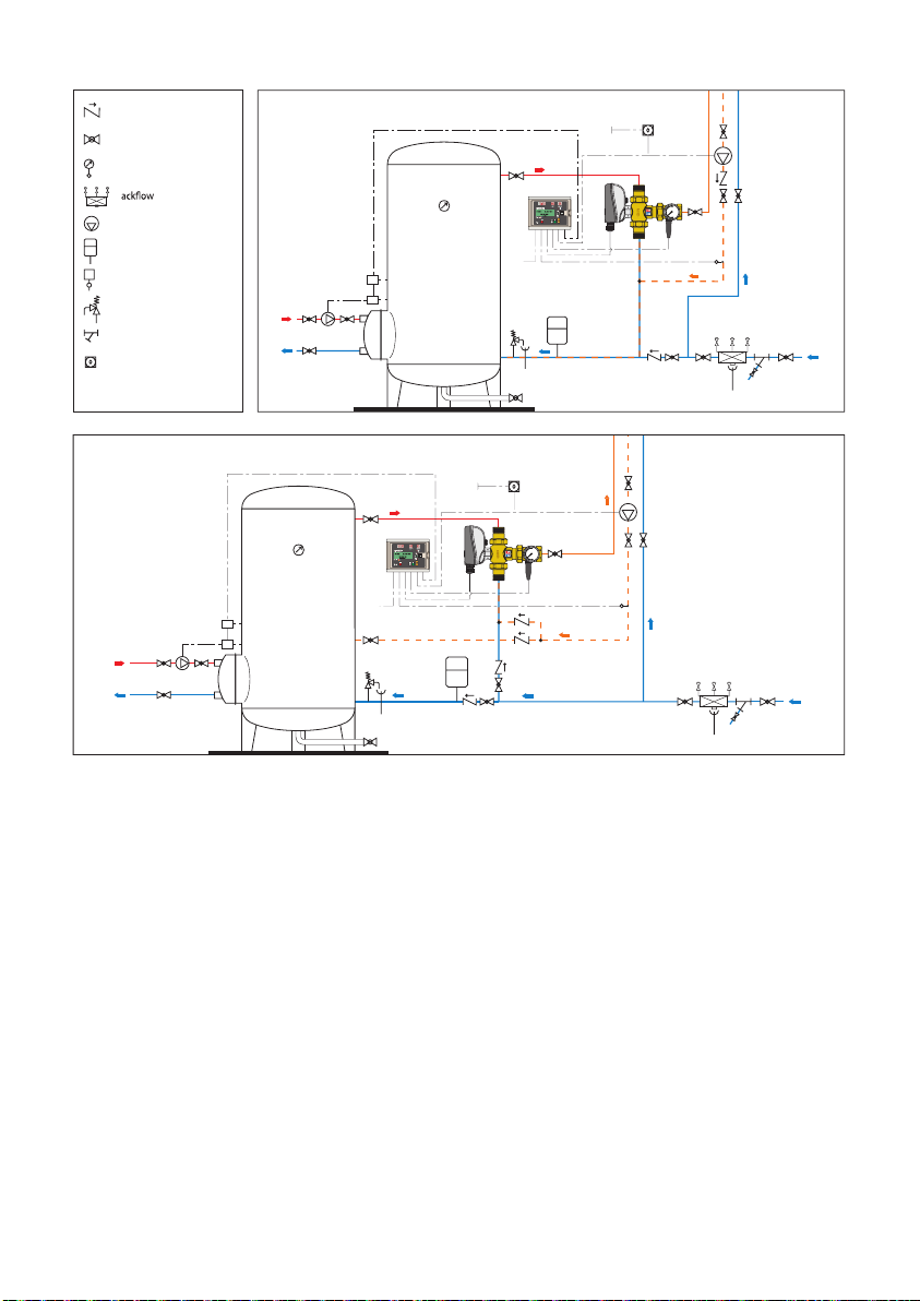
Application diagrams
Non-return valve
Ball valve
Temperature gauge
B
preventer
Pump
Expansion vessel
T
Thermostat
Safety relief valve
Strainer
Clock
Recirculation connected to tank
T2
T1
Recirculation not connected to tank
T2
T1
0
8
0
6
0
°C
4
20
0
0
8
60
0
°C
4
0
2
0
31
Page 32

The following information is provided in accordance with the
Electronic Code of Federal Regulations (FCC) PART 15 — RADIO
FREQUENCY DEVICES §15.105.
§15.105 Information to the user.
(a) For a Class A digital device or peripheral, the instructions furnished
the user shall include the following or similar statement, placed in a
prominent location in the text of the manual:
NOTE: This equipment has been tested and found to comply with the limits for a
Class A digital device, pursuant to part 15 of the FCC Rules. These limits are designed to
provide reasonable protection against harmful interference when the equipment is operated
in a commercial environment. This equipment generates, uses, and can radiate radio
frequency energy and, if not installed and used in accordance with the instruction manual,
may cause harmful interference to radio communications. Operation of this equipment in a
residential area is likely to cause harmful interference in which case the user will be required
to correct the interference at his own expense.
(b) For a Class B digital device or peripheral, the instructions furnished
the user shall include the following or similar statement, placed in a
prominent location in the text of the manual:
NOTE: This equipment has been tested and found to comply with the limits for a
Class B digital device, pursuant to part 15 of the FCC Rules. These limits are designed
to provide reasonable protection against harmful interference in a residential installation.
This equipment generates, uses and can radiate radio frequency energy and, if not
installed and used in accordance with the instructions, may cause harmful interference
to radio communications. However, there is no guarantee that interference will not occur
in a particular installation. If this equipment does cause harmful interference to radio or
television reception, which can be determined by turning the equipment o and on, the user
is encouraged to try to correct the interference by one or more of the following measures:
—Reorient or relocate the receiving antenna.
—Increase the separation between the equipment and receiver.
—Connect the equipment into an outlet on a circuit dierent from that to which the receiver
is connected.
—Consult the dealer or an experienced radio/TV technician for help.
THE LEGIOMIX 6000 SERIES POINT-OF-DISTRIBUTION (ASSE 1017) ELECTRONIC MIXING VALVE IS
INTENDED TO BE BUT ONE COMPONENT IN AN OVERALL RISK MANAGEMENT PLAN AS DESCRIBED
IN ANSI/ASHRAE STANDARD 188 “LEGIONELLOSIS: RISK MANAGEMENT FOR BUILDING WATER
SYSTEMS”. WHEN INSTALLED AND USED AS DESIGNED AND INTENDED, THE LEGIOMIX CAN
HELP REDUCE BACTERIA IN DOMESTIC HOT WATER RECIRCULATION SYSTEMS, HOWEVER DUE
TO SYSTEM-DEPENDENT VARIABLES, 100% ERADICATION CAN NOT BE GUARANTEED. CALEFFI
IS NOT RESPONSIBLE FOR ANY DAMAGES, CONSEQUENTIAL OR OTHER, THAT MAY ARISE FROM
LEGIONELLA ILLNESS WHEN USING THE LEGIOMIX ELECTRONIC MIXING VALVE.
Caleffi North America, Inc.
3883 West Milwaukee Road
Milwaukee, WI 53208
T: 414.238.2360 F: 414.238.2366
32
8-15-2021
 Loading...