

Page 1
www.caleffi.com
38467.05
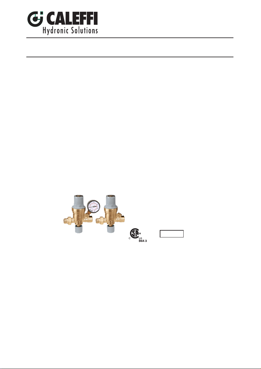
Pre-adjustable filling units
© Copyright 2018 Caleffi
Function
Product Range
The automatic filling valve is a device consisting of a pressure reducing valve with
compensating seat, visual system pressure setting indicator, an inlet filter, anti-scale
internal parts, a shut-off valve and a check valve.
It is installed on the water inlet piping in sealed heating systems, and its main function
is to maintain the pressure of the system stable at a set value, automatically filling up
with water as required.
This valve has been designed as pre-adjustable, which means that it can be
adjusted at the required pressure value before the system charging phase.
After installation, during the filling or topping-off phase, the water feed will stop when
the set pressure is reached filling 50% faster than other valves. There are no levers to
flip or valve to close.
Pre-assembled with the 573 series backflow preventer, the AutoFill™ Combo features
an atmospheric vent which is designed to protect drinking water systems from return
flow, caused by back-siphoning or back pressure, of contaminated fluids. The 573
series has been specifically certified to standards CSA B64.3 and ASSE 1012.
These items are designed for use in closed hydronic systems. Do not use in plumbing
applications. These items do not meet the low-lead plumbing standards of U.S. and
Canada.
553
553 Series
553542A ½” M NPT inlet x ½" FNPT outlet
553549A ½” sweat inlet x ½" FNPT outlet
553642A ½” M NPT inlet x ½" FNPT outlet / gauge
553649A ½” sweat inlet x ½" FNPT outlet / gauge
Technical
Specifications
Filling unit
Materials - body: brass
- cover: PA 66 GF 30
- seals: NBR
Performance
Suitable fluids: water, glycol solution
Max. percentage of glycol: 50%
Max. working pressure: 230 psi (16 bar)
Pressure setting range: 3–60 psi (0.2– 4 bar)
Factory setting: 15 psi (1.035 bar)
Indicator accuracy: ±2 psi (±0.15 bar)
Max. working temperature: 150°F (65°C)
Pressure gauge scale: 0-60 psi / 0-6 bar)
Connections - 553542A 1/2" NPT male inlet x 1/2" NPT female outlet
- 553549A 1/2" sweat inlet x 1/2" NPT female outlet
- 553642A 1/2" NPT male inlet x 1/2" NPT female outlet
- 553649A 1/2" sweat inlet x 1/2" NPT female outlet
1
ASSE 1012
Page 2
SAFETY INSTRUCTION
This safety alert symbol will be used in this manual to draw attention to safety related instructions.
When used, the safety alert symbol means ATTENTION! BECOME ALERT! YOUR SAFETY IS
INVOLVED! FAILURE TO FOLLOW THESE INSTRUCTIONS MAY RESULT IN A SAFETY
HAZARD.
WARNING: This product can expose you to chemicals including lead, which
is known to the State of California to cause cancer and birth defects or other
reproductive harm. For more information go to www.P65Warnings.ca.gov.
CAUTION: All work must be performed by qualified personnel trained in the
proper application, installation, and maintenance of systems in accordance
with all applicable codes and ordinances.
CAUTION: If the automatic filling unit is not installed, commissioned and
maintained properly, according to the instruction contained in the manual, it
may not operate correctly and may endanger the user.
CAUTION: Make sure that all the connecting pipework is water tight.
CAUTION: When making the water connections, make sure that the unit
connecting pipework is not mechanically over-stressed. Over time this could
cause breakages, with consequent water losses which, in turn, could cause
harm to property and/or people.
CAUTION: In the case of highly aggressive water, arrangements must be
made to treat the water before it enters the unit, in accordance with current
legistion. Otherwise the unit may be damaged and will not operate correctly.
LEAVE THIS MANUAL FOR THE USER
2
Page 3
CONSIGNE DE SÉCURITÉ
Ce symbole d'avertissement servira dans ce manuel à attirer l'attention sur la sécurité concernant
instructions. Lorsqu'il est utilisé, ce symbole signifie.
ATTENTION! DEVENEZ ALERTE ! VOTRE SÉCURITÉ EST EN JEU ! NE PAS SUIVRE CES
INSTRUCTIONS PEUT PROVOQUER UN RISQUE DE SECURITE.
AVERTISSEMENT:
le plomb, qui est connu dans l’État de Californie pour causer le cancer, dommages
à la naissance ou autre. Pour plus d’informations rendez-vous www.P65Warnings.
ATTENTION: Tous les travaux doivent être effectués par du personnel qualifié
formé à la bonne application, installation et maintenance des systèmes
conformément aux codes et règlements locaux.
ATTENTION:
service et entretenu correctement, selon les instructions contenues dans ce manuel,
il peut ne pas fonctionner correctement et peut mettre en danger l'utilisateur.
ATTENTION: S'assurer que tous les raccordements sont étanches.
ATTENTION: Lorsque vous effectuez les raccordements d'eau, assurez-vous
que la tuyauterie reliant réducteur de pression n'est pas mécaniquement
des overstressed. Au fil du temps, ceci pourrait causer des ruptures, avec
pour consequence des pertes en eau qui, à leur tour, peuvent causer des
dommages à la propriété et/ou les gens.
Ce produit peut vous exposer à des produits chimiques comme
Si le réducteur de pression, Série 535H, n'est pas installé, mis en
ATTENTION: Dans le cas de l'eau très agressive, des dispositions doivent
être prises pour traiter l'eau avant qu'elle entre dans l'unité, conformément
à l'legistion. Sinon l'appareil peut être endommagé et ne fonctionne pas
correctement.
LAISSEZ CE MANUEL AVEC L’UTILISATEUR
3
Page 4
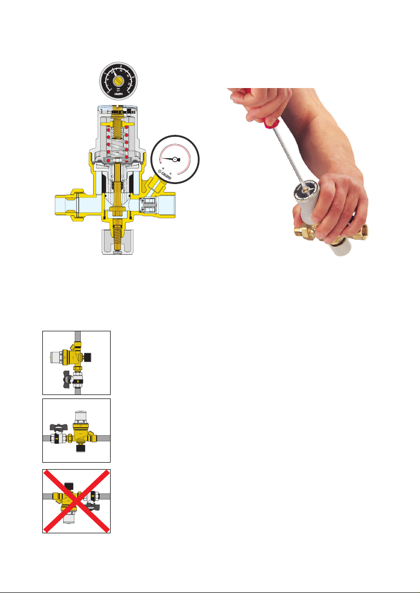
Construction details
Pre-calibration
This
model is
equipped
30
|
|
|
|
|
|
|
|
|
|
|
|
|
|
|
|
|
|
|
|
|
15
|
|
|
|
|
|
|
|
|
|
|
|
|
|
|
|
|
|
2
|
|
|
|
|
|
|
bar
|
|
|
|
|
|
|
|
|
|
0
0
psi
4
|
|
|
60
with a
|
|
|
|
|
|
|
|
|
|
|
|
|
|
|
|
|
|
|
|
|
pressure
|
|
|
|
|
|
|
|
|
|
|
45
|
|
|
|
|
|
|
|
setting indicator
|
|
|
|
|
|
|
|
|
|
|
|
|
|
|
|
|
|
|
|
for the
commissioning
operation. The
system charge
pressure can be
input by means of
the adjusting screw,
before the start of the
system filling phase.
Removable filter
cartidge
Installation
The cartridge containing the operating mechanisms, protected by a
large surface area strainer, is removable. This makes it very easy and
quick to carry out inspections, internal cleaning and even replacement
of the cartridge itself. Water intake is proportional to the air vented from
the system.
1. Filling unit can be installed in either horizontal or vertical position. It is,
however, vital that the unit is not installed upside down.
2. The special method of mechanical pre-adjustment with pressure setting
indicator makes it possible to set the unit to the required value in the system
before the beginning of the filling phase.
3. The unit is normally set at a pressure not less than that obtained by
adding the hydrostatic pressure and 4 psi (0,3 bar).
4. During filling, the internal mechanism will automatically regulate the
pressure until it reaches the required value, without the need to oversee
the filling operation itself. This prevents the system being charged to a
higher pressure than required.
5. Given the pre-calibrating function, the presence of the downstream
pressure gauge is not essential.
6. When the system is filled, the shut-off valve can be closed. In order to
restore the automatic topping-off condition, merely re-open the valve. The
pressure in the system will gradually return to the set pressure.
4
Page 5
D
A
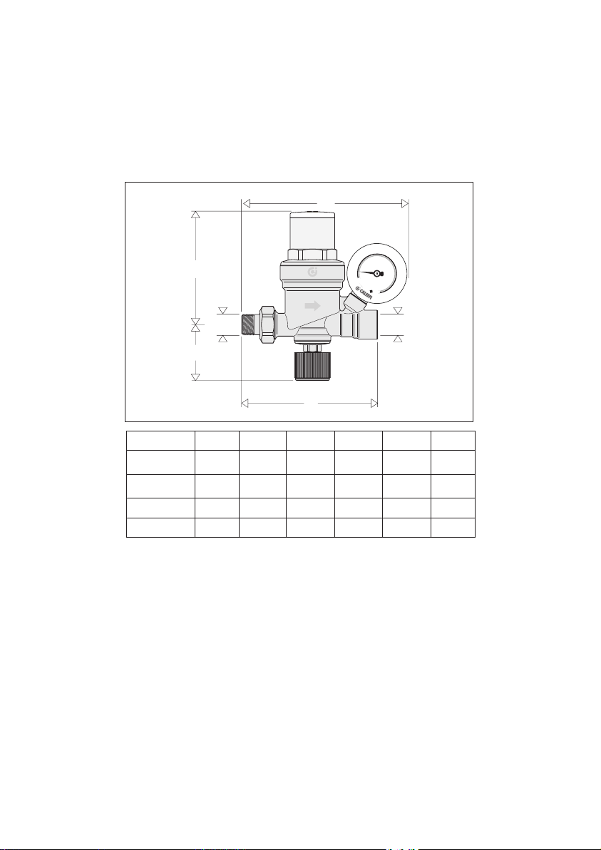
Dimensions
C
30
|
|
|
|
|
|
|
|
|
|
|
|
|
|
|
|
|
|
|
|
15
|
|
|
|
|
|
|
|
|
|
|
|
|
|
|
|
|
|
|
|
|
|
|
|
|
|
|
|
|
|
|
2
|
|
|
|
|
|
|
|
|
|
|
|
|
|
bar
|
|
|
|
|
|
|
|
|
|
|
|
|
|
|
|
|
|
|
|
E
|
|
|
45
|
|
0
|
|
|
0
|
|
|
|
|
|
|
|
psi
|
|
|
|
|
|
|
4
|
|
|
|
|
|
|
|
|
|
|
60
A
A´
D
B
Code A A´ B C D E
553542A1⁄2" NPT1⁄2" NPT 4 ¾"
553549A1⁄2" SWT1⁄2" NPT 4 ¾"
553642A1⁄2" NPT1⁄2" NPT 4 ¾" 5 ¾" 115⁄16" 4"
553649A1⁄2" SWT1⁄2" NPT 4 ¾" 5 ¾" 115⁄16" 4"
__
__
115⁄16" 4"
115⁄16" 4"
5
Page 6
Maintance
Replacement
parts
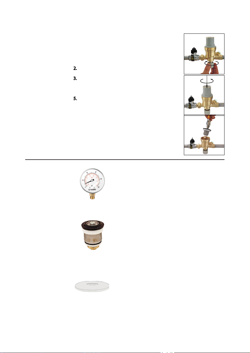
For cleaning, inspection or replacement of the
entire cartridge, proceed as follows:
1. Isolate the unit.
2. Open the lower control knob.
3. Unscrew the adjusting screw until it stops.
4. Remove the upper cover.
5. Extract the cartridge using pliers.
6. The entire unit, after inspection, can be
reassembled or replaced using a spare cartridge.
7. Re-adjust the equipment.
2
3
5
NA10363
F59650
NA10197
6
Replacement gauge 0-60 psi/0-4 bar, ¼" NPT
AutoFill™ 553 series replacement cartridge
AutoFill™ clear plastic disc cover
Page 7
|
|
|
|
|
|
|
|
|
|
|
|
|
|
|
|
|
|
|
|
|
|
|
|
|
|
|
|
|
|
|
|
|
|
|
|
|
|
|
|
|
|
|
|
|
|
|
|
|
|
|
|
|
|
|
|
|
|
|
|
|
|
|
|
|
|
|
|
|
|
|
|
|
|
|
|
|
|
|
|
|
|
|
|
|
|
|
|
|
|
|
|
|
|
|
|
|
|
|
|
|
|
|
|
|
|
|
|
|
|
|
|
|
|
|
|
|
|
|
1
5
30
60
0
4
2
p
s
i
bar
P
A
T
F
T
T
BACKFL
O
W
PREV
Series:
5
73
Sizes:
1/2”
- 3
/4”
S/
N
VENT
45
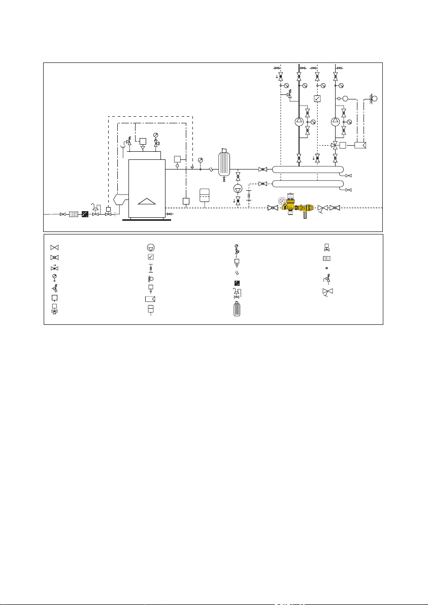
Application diagram
T
T
P
T
|
|
|
|
|
|
|
|
|
|
|
|
|
|
|
|
|
|
|
|
|
|
|
|
|
|
|
|
|
|
30
|
|
|
|
|
|
|
|
|
|
|
|
|
|
|
|
|
|
|
|
|
|
|
|
|
|
|
|
|
|
|
|
|
2
|
|
|
|
|
|
|
|
|
|
|
|
|
|
bar
|
|
|
|
|
|
|
|
|
|
|
|
|
4
|
|
60
|
|
|
|
|
|
|
5
|
|
|
1
i
|
|
s
|
|
p
|
|
|
A
F
|
|
0
|
|
|
|
|
|
|
|
/4”
PREV
W
- 3
O
73
5
1/2”
N
BACKFL
Series:
Sizes:
S/
45
VENT
Shut-off valve
Ball valve
BALLSTOP
Thermometer
Differential by-pass valve
F
Flow switch
Zone valve
Pump
FlowCal
Flow meter
T
Temperature probe
T
Safety thermostat
Regulator
Expansion vessel
™
P
Pressure switch
Control pocket
Gas filter
Gas regulator
Air separator
3-way valve
A
Fuel shut-off valve
Anti-vibration joint
Sensor pocket
Safety valve
Y-strainer
7
Page 8

Scan to view
·
553 AutoFill
Installation Tip
TM
Caleffi North America, Inc.
3883 West Milwaukee Road
Milwaukee, WI 53208
T: 414.238.2360 F: 414.238.2366
7-23-18
8
Page 9
www.caleffi.com
CALEFFI
Backflow preventer with intermediate atmospheric vent
38517.06
© Copyright 2018 Caleffi
573 Series
Installation, commissioning and servicing instructions
Function
The backflow preventer with atmospheric vent is designed to protect
drinking water systems from the return, caused by backsiphonage or
backpressure, of contaminated fluids.
The Caleffi 573 series Is certified by ICC-ES to be in compliance with
the International Plumbing Code (IPC), International Residential Code
(IRC), Uniform Plumbing Code (UPC), and standards ASSE 1012-
USC
ASSE 1012
Technical characteristics
Connections: 1/2”- 3/4” NPT female with union
1/2” SWT with union
1/2" press with union
Materials: Body: low lead brass
Filter: stainless steel
Check valve: PSU
Check valve stem: brass
Diaphragm: peroxide-cured EPDM
Seals: peroxide-cured EPDM
Maximum working pressure: 175 psi (12 bar)
Maximum working temperature: 210°F (99°C)
Emergency back pressure temperature: 250°F (121°C)
Medium: water
2009, and CSA B64.3-94. Additionally, it is also certified by ICC-ES
to be in compliance with standard NSF/ANSI 372-2011, Drinking
Water System Components – Lead Content Reduction of Lead
in Drinking Water Act, California Health and Safety Code 116875
S.3874, Reduction of Lead in Drinking Water Act.
Product range
573 series backflow preventer with atmospheric vent
size 1/2” sweat connection with union
size 1/2" press connection with union
size 1/2”- 3/4” NPT female threaded connection with union
Certified to: CSA B64.3-94 and ASSE 1012-2009
NSF/ANSI 372-2011, Drinking Water System Components-Lead Content
Reduction of Lead in Drinking Water Act, California Health and Safety
Code 116875 S.3874, Reduction in Drinking Water Act, certified by ICC-ES, file PMG-1360.
1
Page 10
SAFETY INSTRUCTION / CONSIGNE DE SÉCURITÉ
This safety alert symbol will be used in this manual to draw attention to safety related instructions.
When used, the safety alert symbol means ATTENTION! BECOME ALERT! YOUR SAFETY IS
INVOLVED! FAILURE TO FOLLOW THESE INSTRUCTIONS MAY RESULT IN A SAFETY
HAZARD.
Ce symbole d'avertissement servira dans ce manuel à attirer l'attention sur la sécurité concernant instructions. Lorsqu'il
est utilisé, ce symbole signifie ATTENTION ! DEVENEZ ALERTE ! VOTRE SÉCURITÉ EST EN JEU ! NE PAS
SUIVRE CES INSTRUCTIONS PEUT PROVOQUER UN RISQUE DE SECURITE.
WARNING: This product can expose you to chemicals including lead, which is known
to the State of California to cause cancer and birth defects or other reproductive
harm. For more information go to www.P65Warnings.ca.gov.
AVERTISSEMENT:
Ce produit peut vous exposer à des produits chimiques comme
le plomb, qui est connu dans l’État de Californie pour causer le cancer, dommages à
la naissance ou autre. Pour plus d’informations rendez-vous www.P65Warnings.ca.gov.
CAUTION: All work must be performed by qualified personnel trained in the proper application,
installation, and maintenance of systems in accordance with all applicable codes and ordinances.
ATTENTION: Tous les travaux doivent être effectués par du personnel qualifié formé à la bonne
application, installation et maintenance des systèmes conformément aux codes et règlements locaux.
CAUTION: If the backflow preventer is not installed, commissioned and maintained properly, according
to the instructions contained in this manual, it may not operate correctly and may endanger the user.
ATTENTION: Si Disconnecteur n'est pas installé, mis en service et entretenu correctement, selon les
instructions contenues dans ce manuel, il peut ne pas fonctionner correctement et peut mettre en danger
l'utilisateur.
CAUTION: Make sure that all the connecting pipework is water tight.
ATTENTION: S'assurer que tous les raccordements sont étanches.
CAUTION: When making the water connections, make sure that the backflow preventer connecting
pipework is not mechanically over-stressed. Over time this could cause breakages, with consequent
water losses which, in turn, could cause harm to property and/or people.
ATTENTION: Lorsque vous effectuez les raccordements d'eau, assurez-vous que la tuyauterie reliant
disconnecteur n'est pas mécaniquement des overstressed. Au fil du temps, ceci pourrait causer des
ruptures, avec pour conséquence des pertes en eau qui, à leur tour, peuvent causer des dommages à
la propriété et/ou les gens.
CAUTION: Water temperatures higher than 100°F can be dangerous. During the installation,
commissioning and maintenance of the backflow preventer, take the necessary precautions to ensure
that such temperatures do not endanger people.
ATTENTION: Les températures de l'eau supérieure à 100°F peut être dangereux. Au cours de l'installation,
mise en service et l'entretien de la disconnecteur, prendre les précautions nécessaires afin de s'assurer
que de telles températures ne compromettent pas les gens.
CAUTION: In the case of highly aggressive water, arrangements must be made to treat the water before
it enters the backflow preventer, in accordance with current legislation. Otherwise the valve may be
damaged and will not operate correctly.
ATTENTION: Dans le cas de l'eau fortement agressifs, des dispositions doivent être prises pour traiter
l'eau avant qu'elle ne pénètre dans le disconnecteur, conformément à la législation actuelle. Sinon la
soupape pourrait être endommagée et ne fonctionnent pas correctement.
LEAVE THIS MANUAL FOR THE USER
LAISSEZ CE MANUEL AVEC L’UTILISATEUR
2
Page 11
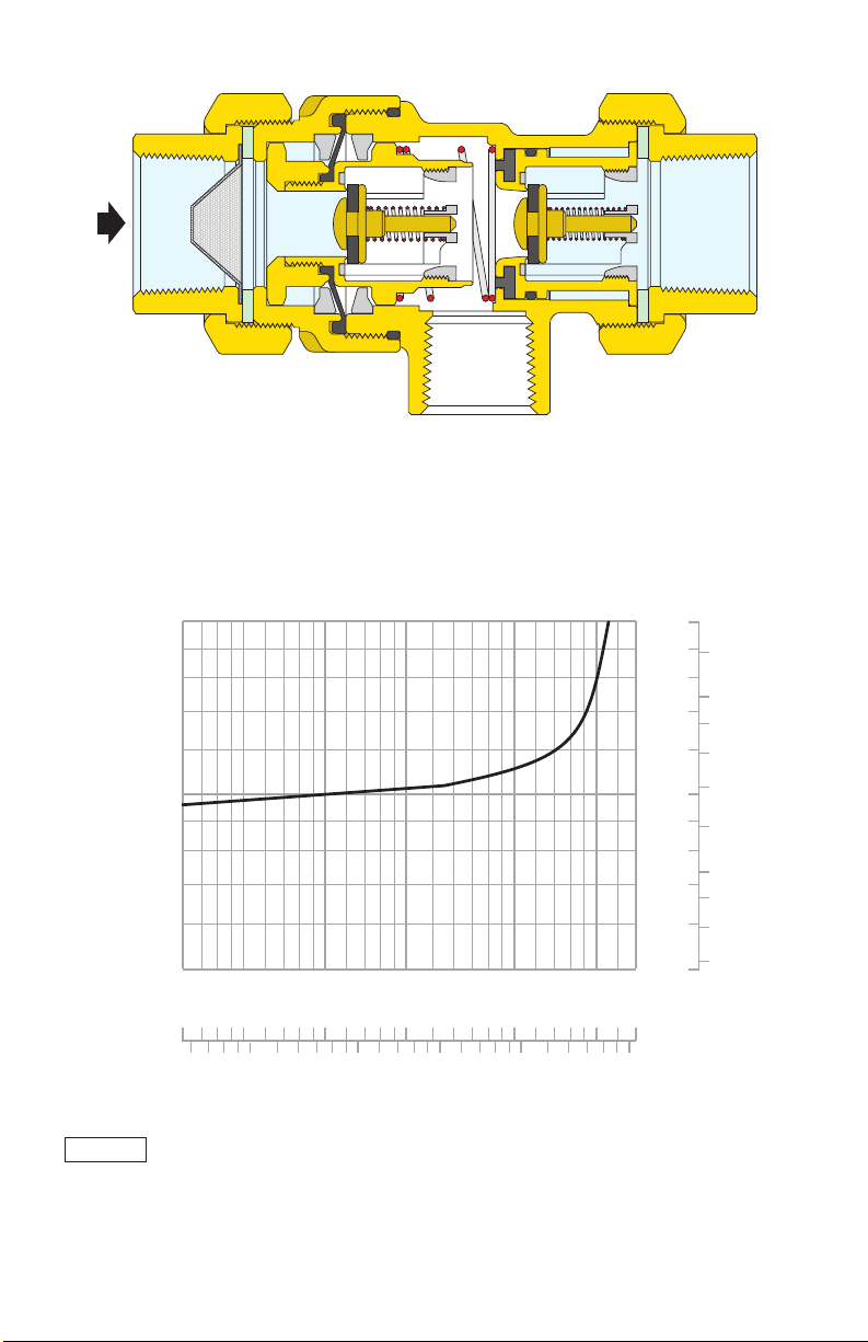
Flow rate graph
(l/min)
VENT
Cv = 0.7
∆p (psi)
20
10
5
.3
0
.5
0
(psi) (bar)
20
1
10
0.5
5
)
1
2
2
5
10
5
20
10
15
50
gpm
(
G
3
Page 12

Installation
The Caleffi 573 series backflow preventer with atmospheric vent must be installed in accordance
with the diagrams contained in this instruction manual taking into account all the applicable Codes
and Regulations.
Before installing a Caleffi 573 series backflow preventer, the system must be thoroughly flushed to
remove impurities or any debris which may have accumulated during installation. Failure to remove
dirt or debris may affect performance and the manufacturer’s guarantee.
The Caleffi 573 series backflow preventer must be installed preferably horizontally and following
the flow direction indicated by the arrow on the valve body.
The Caleffi 573 series backflow preventer must be installed with one isolating valve and a strainer
upstream and one isolating valve downstream.
The Caleffi 573 series backflow preventer must be installed in an accessible location to facilitate
testing and servicing.
The Caleffi 573 series backflow preventer must be installed with the vent port connected via an
air gap to a discharge line, in accordance with the plumbing code requirements and keeping a
minumum distance of 12” from the floor.
Do not install where the discharge can could cause damage.
If field testing is required by code, it must be installed in accordance with the relevant diagram in
this instruction manual.
Scan to view
Installation Tip
·
573 Backflow Preventer
4
Page 13
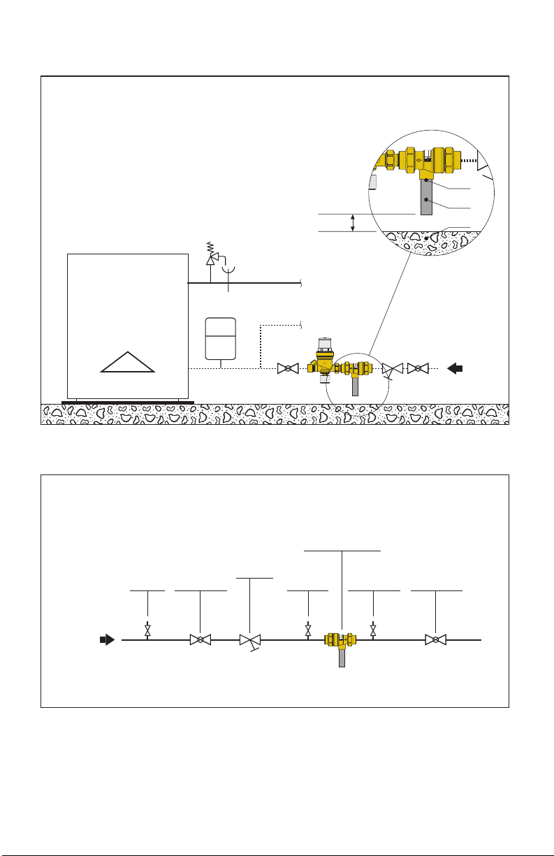
Installation diagram
BACKFL
O
W
PREVE
VENT
Heating system application
Air gap
/4”
- 3
73
5
1/2”
N
Series:
Sizes:
S/
Vent
Drain
Floor
/4”
PREV
W
- 3
O
73
5
1/2”
N
BACKFL
Series:
Sizes:
S/
VENT
MAINS
SUPPLY
Field testing installation
Backflow preventer
573 series
Inlet test
cock
Upstream
shut-off valve
Y-strainer
MAINS
SUPPLY
Upstream
5
test cock
Downstream
test cock
/4”
PREV
W
- 3
O
73
5
1/2”
N
BACKFL
Series:
Sizes:
S/
VENT
Downstream
shut-off valve
Page 14

Field testing procedure
1) Check operation of the discharge. When inlet water pressure drops to atmospheric, the valve
must open the vent port and discharge the contained amount of water in the valve body.
a. -close shutoff valves upstream and downstream.
b. -open the upstream test cock
The water contained in the body must be discharged, indicating that the diaphragm has opened
the vent port.
2) Check for tightness of the internal second check valve. When backpressure is applied to the
downstream side of the valve, the internal second check valve must close back drip tight on its
seat.
a. -close shutoff valves upstream and downstream.
b. -open the upstream test cock
c. -install a removable bypass hose connecting inlet test cock to downstream test cock and open
them for admitting pressure to the downstream side of the internal second check valve
Water must not drip from the vent port indicating that the second check valve is not leaking.
Service
The internal parts of the backflow preventer are replaceable. Spare parts are available upon
request.
Caleffi North America, Inc.
3883 West Milwaukee Road
Milwaukee, WI 53208
T: 414.238.2360 F: 414.238.2366
6-6-18
 Loading...