

Page 1
USC
www.caleffi.com
CALEFFI
Backflow preventer with intermediate atmospheric vent
Installation, commissioning and servicing instructions
Function
The backflow preventer with atmospheric vent is designed to
protect drinking water systems from the return, caused by
backsiphonage or backpressure, of contaminated fluids.
The Caleffi 573 series has been specifically certified to standards
CSA B64.3 and ASSE 1012.
Product range
ASSE
1012
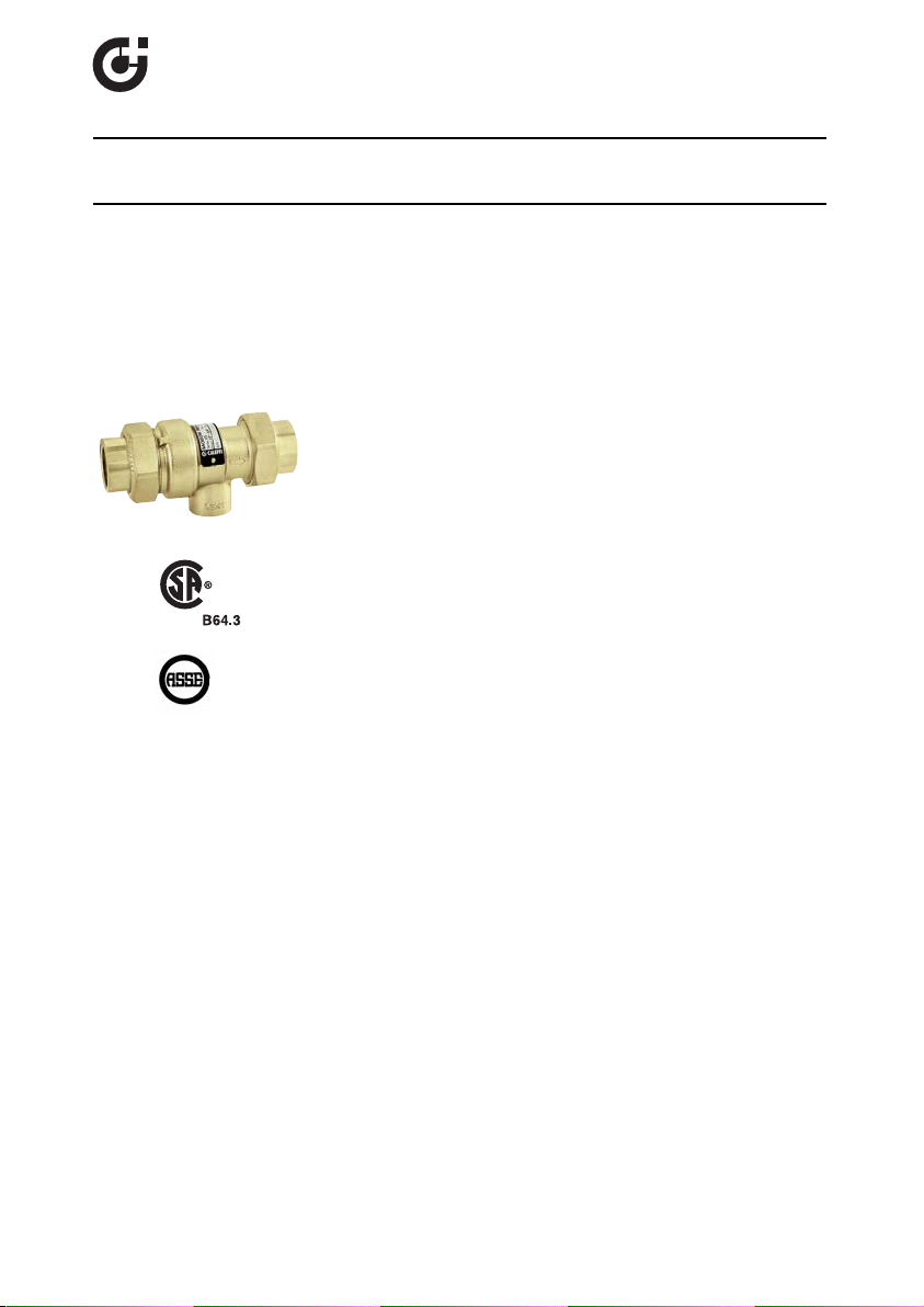
573 series backflow preventer with atmospheric vent
size 1/2”- 3/4” NPT female threaded connection with union
size 1/2” sweat connection with union
38517.04
573 Series
Technical characteristics
Connections: 1/2”- 3/4” NPT female with union
Materials: Body: brass
Maximum working pressure: 175 psi (12 bar)
Maximum working temperature: 210°F (99°C)
Emergency back pressure temperature: 250°F (121°C)
Medium: water
Certified to: CSA B64.3 and ASSE 1012
Filter: stainless steel
Check valve: PSU
Check valve stem: brass
Diaphragm: EPDM
Seals: EPDM
1
1/2” SWT with union
Page 2
SAFETY INSTRUCTION
This safety alert symbol will be used in this manual to draw attention to safety related
instructions. When used, the safety alert symbol means ATTENTION! BECOME ALERT!
YOUR SAFETY IS INVOLVED! FAILURE TO FOLLOW THESE INSTRUCTIONS MAY
RESULT IN A SAFETY HAZARD.
CAUTION: All work must be performed by qualified personnel trained in the
proper application, installation, and maintenance of systems in accordance
with all applicable codes and ordinances.
CAUTION: If the backflow preventer is not installed, commissioned and
maintained properly, according to the instructions contained in this
manual, it may not operate correctly and may endanger the user.
CAUTION: Make sure that all the connecting pipework is water tight.
CAUTION: When making the water connections, make sure that the
backflow preventer connecting pipework is not mechanically overstressed. Over time this could cause breakages, with consequent water
losses which, in turn, could cause harm to property and/or people.
CAUTION: Water temperatures higher than 100°F can be dangerous.
During the installation, commissioning and maintenance of the backflow
preventer, take the necessary precautions to ensure that such
temperatures do not endanger people.
CAUTION: In the case of highly aggressive water, arrangements must be
made to treat the water before it enters the backflow preventer, in
accordance with current legislation. Otherwise the valve may be
damaged and will not operate correctly.
Leave this manual for the user.
2
Page 3

Flow rate graph
10
2
5
10
5
20
50
∆p (psi)
G (l/min) (
gpm
)
20
10
5
(psi) (bar)
20
1
0
.5
10
2
5
15
1
0.5
0.3
VENT
Cv = 0.7
3
Page 4

Installation
The Caleffi 573 series backflow preventer with atmospheric vent must be installed in
accordance with the diagrams contained in this instruction manual taking into account all the
applicable Codes and Regulations.
Before installing a Caleffi 573 series backflow preventer, the system must be thoroughly
flushed to remove impurities or any debris which may have accumulated during installation.
Failure to remove dirt or debris may affect performance and the manufacturer’s guarantee.
The Caleffi 573 series backflow preventer must be installed preferably horizontally and
following the flow direction indicated by the arrow on the valve body.
The Caleffi 573 series backflow preventer must be installed with one isolating valve and a
strainer upstream and one isolating valve downstream.
The Caleffi 573 series backflow preventer must be installed in an accessible location to
facilitate testing and servicing.
The Caleffi 573 series backflow preventer must be installed with the vent port connected via
an air gap to a discharge line, in accordance with the plumbing code requirements and
keeping a minumum distance of 12” from the floor.
Do not install where the discharge can could cause damage.
If field testing is required by code, it must be installed in accordance with the relevant diagram
in this instruction manual.
4
Page 5
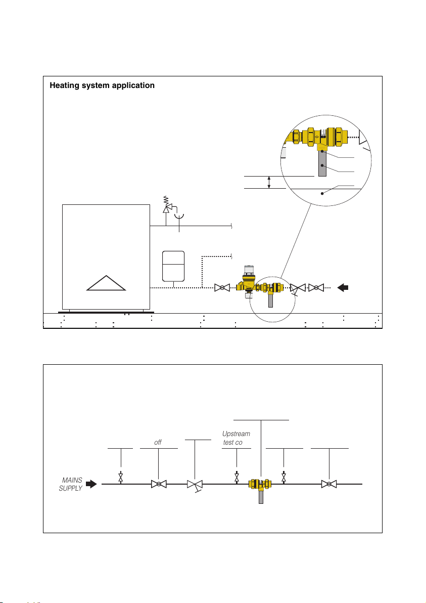
Installation diagram
MAINS
SUPPLY
Drain
Vent
Floor
Air gap
a
a
a
a
a
a
a
BACKFL
O
W
PREVENTER
Series:
5
73
Sizes:
1/2”
- 3
/4”
S/
N
VENT
aa
a
a
a
a
a
a
a
a
a
a
a
aa
a
aa
a
a
a
a
a
a
BACKFL
O
W
PREVENTER
Series:
5
73
Sizes:
1/2”
- 3
/4”
S/
N
VENT
MAINS
SUPPLY
Upstream
test cock
Upstream
shut-off valve
Downstream
shut-off valve
Downstream
test cock
Inlet test
cock
Backflow preventer
573 series
Y-strainer
BACKFL
O
W
PREVENTER
Series:
5
73
Sizes:
1/2”
- 3
/4”
S/
N
VENT
Heating system application
Field testing installation
5
Page 6

Field testing procedure
CALEFFI
1) Check operation of the discharge. When inlet water pressure drops to atmospheric, the
valve must open the vent port and discharge the contained amount of water in the valve body.
a. -close shutoff valves upstream and downstream.
b. -open the upstream test cock
The water contained in the body must be discharged, indicating that the diaphragm has
opened the vent port.
2) Check for tightness of the internal second check valve. When backpressure is applied to
the downstream side of the valve, the internal second check valve must close back drip tight
on its seat.
a. -close shutoff valves upstream and downstream.
b. -open the upstream test cock
c. -install a removable bypass hose connecting inlet test cock to downstream test cock and
open them for admitting pressure to the downstream side of the internal second check valve
Water must not drip from the vent port indicating that the second check valve is not leaking.
Service
The internal parts of the backflow preventer are replaceable. Spare parts are available upon
request.
Caleffi North America, Inc.
3883 West Milwaukee Road
Milwaukee, WI 53208
T: 414.238.2360 F: 414.238.2366
 Loading...