

Page 1
Pre-adjustable filling units
R
E
G
I
S
T
E
R
E
D
BSI EN ISO 9001:2000
Cert. n° FM 21654
UNI EN ISO 9001:2000
Cert. n° 0003
USC
& backflow preventer
series 553 - 573
CALEFFI
01061/08 NA
Replaces 01061/04 NA
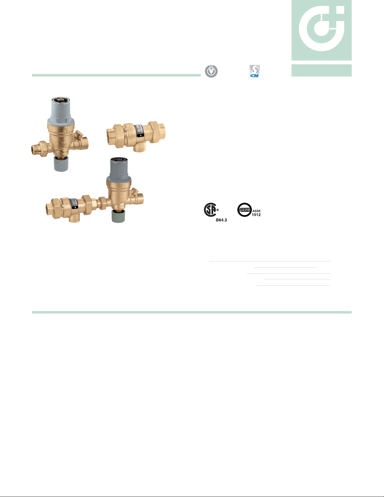
Function
The automatic filling unit is a device consisting of a pressure
reducing valve with compensating seat, an inlet filter, a shut-off
valve and a check valve.
It is installed on the water inlet piping in sealed heating systems,
and its main function is to maintain the pressure of the system
stable at a set value, automatically filling up with water as required.
This product has the characteristic of being pre-adjustable,
which means that it can be adjusted at the required pressure
value before the system charging phase.
After installation, during the filling or topping-off phase, the water
feed will stop when the set pressure is reached.
A pre-assembled version is also available, complete with upstream
backflow preventer.
Product range
Code 553542A Filling unit with pressure gauge and pressure setting indicator Size 1/2”
Series 573 Backflow preventer with intermediate atmospheric vent with threaded connections Size 1/2” - 3/4”
Series 573 Backflow preventer with intermediate atmospheric vent with sweat connections Size 1/2”
Code 573002A Charging unit complete with backflow preventer 573 series with threaded connections Size 1/2”
Code 573009A Charging unit complete with backflow preventer 573 series with sweat connections Size 1/2”
Technical specification
Filling unit
Material: Body: brass
Cover: PA 66 GF 30
Seals: NBR
Maximum Working Pressure: 230 psi (16 bar)
Pressure setting range: 3÷60 psi (0.2÷4 bar)
Factory setting: 15 psi (1.035 bar)
Indicator accuracy: ±2 psi (±0.15 bar)
Maximum Working Temperature: 150°F (65°C)
Connection: Inlet: 1/2” NPT Male
with union tailpiece
Outlet: 1/2” NPT Female
Backflow preventer
Material: Body: brass
Filter: stainless steel
Check valve: PSU
Check valve stem: brass
Diaphragm: EPDM
Seals: EPDM
Maximum working pressure: 175 psi (12 bar)
Maximum working temperature: 210°F (99°C)
Medium: water
Certified to: CSA B64.3 and ASSE 1012
Connections: 1/2”-3/4” NPT female with union
1/2” sweat with union
Page 2
0
1
2
3
4
0
10
20
30
40
50
CALEFFI
bar
psi
Dimensions
E
DC
A
Code
553542A
A
1/2"
4
B
13/16
PREVE
/4”
W
-3
O
73
5
1/2”
N
BACKFL
Series:
Sizes:
A’
1/2”
3/4”
1/2”
SWT
NPT
VENT
C
B
S/
1/2”
1/2”
1/2”
1/2”
A’
PREV
/4”
W
-3
O
73
5
1/2”
N
BACKFL
Series:
Sizes:
1/2"
1/2”
S/
VENT
B
C
A
A’
1/2"
SWT
1/2”
NPT
B
1/2”
1/2”
C
9
3/16
“
1/8
“
9
A
D E
D
C
B
1
4
3/4
“
3/8
“
5/8
“
3/8
“
Code
“
573002A
“
573009A
4
4
4
11/16
5/8
1
1
“
3/8
“
3/8
1
A’
D
E
1
3/8
“
4”
1
3/8
“
4”
A
D
A
Code
B
573403A
573503A
573409A
“C1
15/16
“D4”
573493A
1/2”
3/4”
1/2”
1/2”
A
SWT
1/2”
SWT
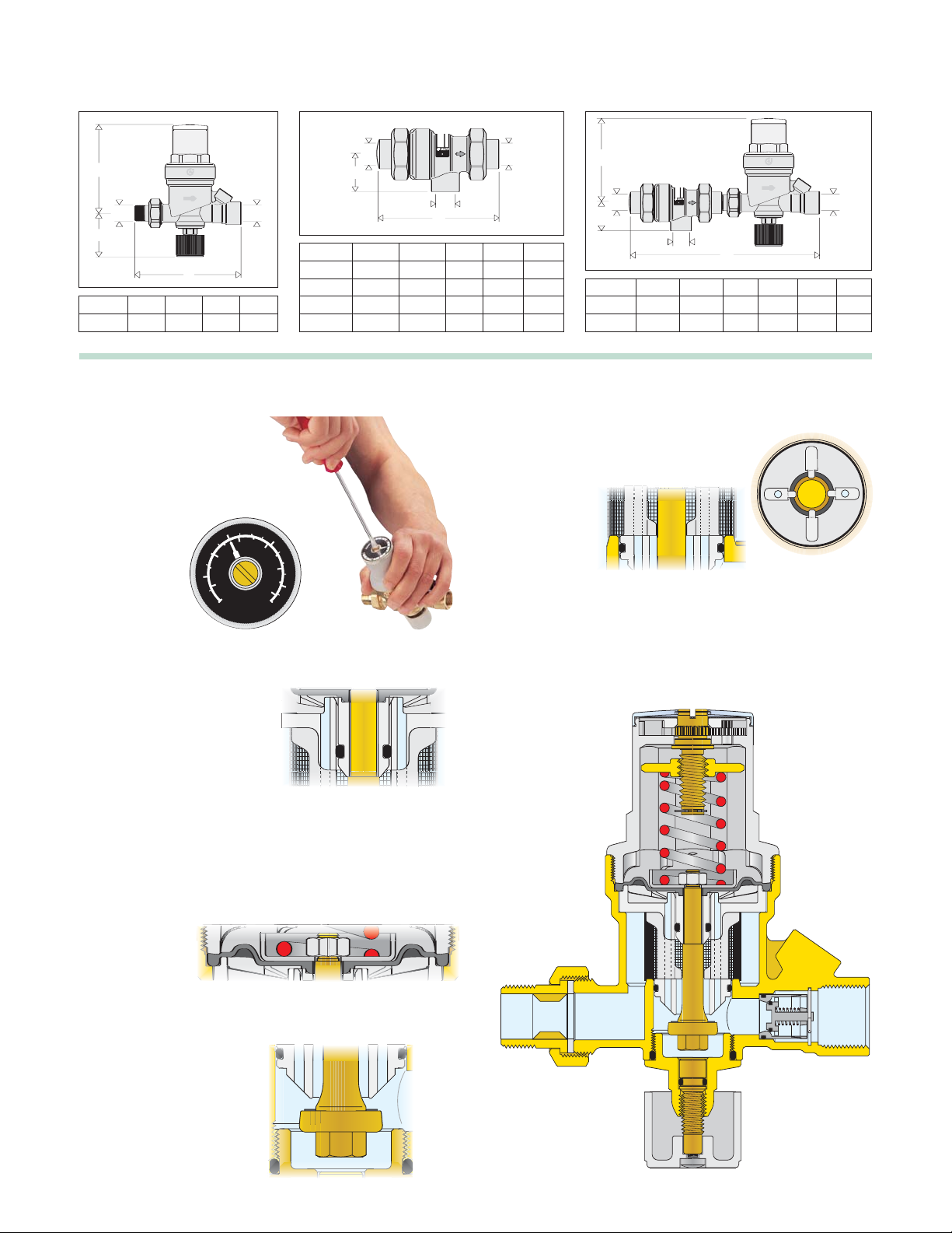
Construction details
Pre-calibration
This model is equipped with a
pressure setting indicator for
the commissioning operation.
The system charge pressure
can be input by
means of the
adjusting screw,
before the start
of the system
charging phase.
Anti-stick materials
The central housing containing
the moving parts and the internal
compensating spindle are made
of a low adhesion coefficient
plastic. This material minimises
the risk of for
mation of scale
deposits, the main cause of
malfunctions.
Diaphragm-seat seal
Spindle guide
In order to reduce the frictional
surfaces, the spindle unit guide has
been positioned in the upper part of
the device.
It consists of four
spokes formed
directly on the
plastic central
support.
Removable filter cartridge
The cartridge containing the operating mechanisms, protected by
a large surface area strainer, is removable. This makes it very easy
and quick to carry out inspections, internal cleaning and even
replacement of the cartridge itself.
The useful working surface of the diaphragm is particularly
large, in order to guarantee greater precision and sensitivity
when working with minimum pressure differences.
This feature is also
useful in that it
gives greater power
to the sliding of
the spindle and
overcomes friction.
In view of the low flow rates involved, the filling unit seat has been
designed with the smallest possible diameter.
➩
This factor, combined with
the extended surface of
the diaphragm, creates an
optimum dimensional ratio
for a piece of equipment
which must maintain its
operating characteristics
unchanged over time.
Page 3

Installation
10
2
5
10
5
20
50
Δp
(psi)
G
(l/min) (
gpm
)
20
10
5
(psi) (bar)
20
1
0.5
10
2
5
15
1
0.5
0.3
Cv = 0.7
Maintenance
Filling unit can be installed in either horizontal
1.
It is, however, vital that the unit is not installed
2. The special method of mechanical pre-adjustment with pressure
setting indicator makes it possible to set the unit to the required value
in the system before the beginning of the filling phase.
3. The unit is normally set at a pressure not less than that obtained by
adding the hydrostatic pressure and 4 psi (0,3 bar).
4. During filling, the internal mechanism will automatically regulate the
pressure until it reaches the required value, without the need to
oversee the filling operation itself. This prevents the system being
charged to a higher pressure than required.
5. Given the pre-calibrating function, the presence of the downstream
pressure gauge is not essential.
6. When the system is filled, the shut-off valve can be closed. In order
to restore the automatic topping-off condition, merely re-open the
valve. The pressure in the system will gradually return to the set
pressure.
or vertical position.
upside down.
For cleaning, inspection or
replacement of the entire
cartridge, proceed as follows:
1. Isolate the unit.
2. Open the lower control
knob.
3. Unscrew the adjusting
screw until it stops.
4. Remove the upper cover.
5. Extract the cartridge using
pliers.
6. The entire unit, after
inspection, can be
reassembled or replaced
using a spare cartridge.
7. Re-adjust the equipment.
2
3
5
Backflow preventer
The backflow preventer with atmospheric vent is designed to
protect drinking water systems from the return, caused by
backsiphonage or backpressure, of contaminated fluids.
The Caleffi 573 series has been specifically certified to standards
CSA B64.3 and ASSE 1012.
➩
VENT
Flow rate graph
Code 573002A - 573009A
Charging unit consists of:
- Backflow preventer with intermediate atmospheric vent,
573 series
- Filling unit, 553 series
Page 4

Application diagram
V
TT
P
T
Shut-off valve
Ball valve
Ballstop
Thermometer
Differential by-pass valve
F
Flow switch
Zone valve
F
A
Pump
Autoflow
Flow meter
T
Temperature probe
T
Safety thermostat
Regulator
Expansion vessel
3-way valve
P
Pressure switch
Control pocket
Gas filter
Gas regulator
Air separator
PRE
/4”
W
-3
O
73
5
1/2”
N
BACKFL
Series:
Sizes:
S/
VENT
A
Fuel shut-off valve
Anti-vibration joint
Sensor pocket
Safety valve
SPECIFICATION SUMMARIES
Code 553542A
Filling unit with pressure gauge connection and pressure setting indicator. 1/2” NPT Male with union x Female threaded
connection. Brass body. Nylon plastic cover. Sliding surfaces in anti-stick plastic. Diaphragm and seals in NBR. Cartridge
removable for maintenance operations. Maximum working temperature 150°F. Maximum inlet pressure 230 psi. Setting range
3÷60 psi. Pressure indicator for pre-adjustment of device, accuracy ±2 psi. Complete with isolating valve, filter and check valve.
Series 573
Backflow preventer with atmospheric vent. Certified to CSA B64.3 and ASSE 1012. 1/2” (3/4”) NPT female threaded
connection with union or 1/2” sweat with union. Brass body, filter in stainless steel, check valve in PSU, diaphragm and
seals in EPDM. Maximum working pressure 175 psi. Maximum working temperature 210°F.
Code 573002A - 573009A
Charging unit complete with backflow preventer 1/2” NPT Female threaded with union or 1/2” sweat with union inlet connection
and 1/2” NPT Female threaded outlet connection. Maximum working temperature 150°F. Maximum inlet pr
We reserve the right to change our products and their relevant technical data, contained in this publication, at any time and without prior notice.
essure 175 psi.
CALEFFI
3883 West Milwaukee Road / Milwaukee, WI 53208
Tel: 414.238.2360 / Fax: 414.238.2366 / www.caleffi.us
Caleffi North America, Inc.
© Copyright 2008 Caleffi
 Loading...