

Page 1
www.caleffi.com
CALEFFI
38456.06
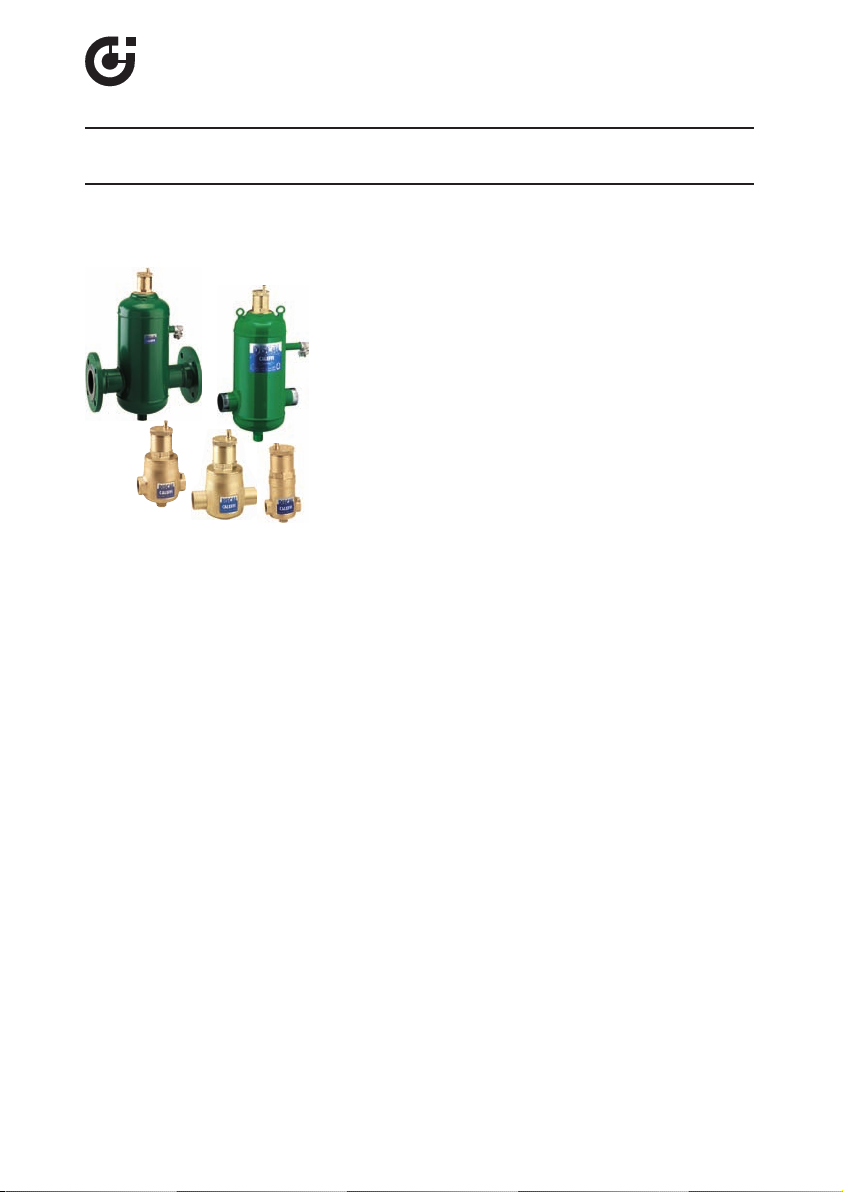
DISCAL®air separator 551 Series
Installation, commissioning and servicing instructions
Function
Air separators are used to continuously remove the air contained
in the hydronic circuits of heating and cooling systems. The air
discharge capacity of these devices is very high. They are
capable of removing automatically all the air present in the
system down to micro-bubble level.
The circulation of fully de-aerated water enables the equipment
to operate under optimum conditions, free from any noise,
corrosion, localized overheating or mechanical damage. Microbubbles, fusing with each other, increase in volume (get larger)
until they become large enough to rise to the top where they are
automatically released.
Product range
Series 551 DISCAL air separator compact, sizes 3/4” Sweat; 3/4” NPT female - 1/2” female drain
Series 551 DISCAL air separator with 1/2” female drain, sizes 3/4” - 1” - 1 1/4” - 1 1/2” - 2” NPT female
Series 551 DISCAL air separator with 1/2” female drain, sizes 1” - 1 1/4” - 1 1/2" - 2" Sweat
Series 551 DISCAL air separator with flanged connections, sizes 2” - 6” ANSI
Series 551 DISCAL air separator with male thread connections, sizes 2” - 4” NPT
Technical specifications
Brass body air separators
Connections: - Main: compact 3/4” sweat; 3/4” NPT female
Materials: - body: brass
Suitable fluids: water, glycol solution
Max percentage of glycol: 50%
Max working pressure: 150 psi (10 bar)
Temperature range: 32–250°F (0–120°C)
Steel body air separator
Connections: - Flanged: 2”–6” ANSI 150 CLASS
Materials: - body: epoxy resin painted steel
Suitable fluids: water, glycol solution
Max working pressure: 150 psi (10 bar)
Max percentage of glycol: 50%
Temperature range: 32–250°F (0–120°C)
- Drain: 1/2” NPT female
- int. element: stainless steel (compact version)
- seal: EPDM
- Threaded 2” - 4” NPT male
- Drain: 1” NPT male
- int. element: stainless steel
- seal: EPDM
3/4” - 1” - 1 1/4” - 1 1/2” - 2” NPT female
1
1” - 1 1/4” - 1 1/2" - 2" sweat
PA66G30
Page 2
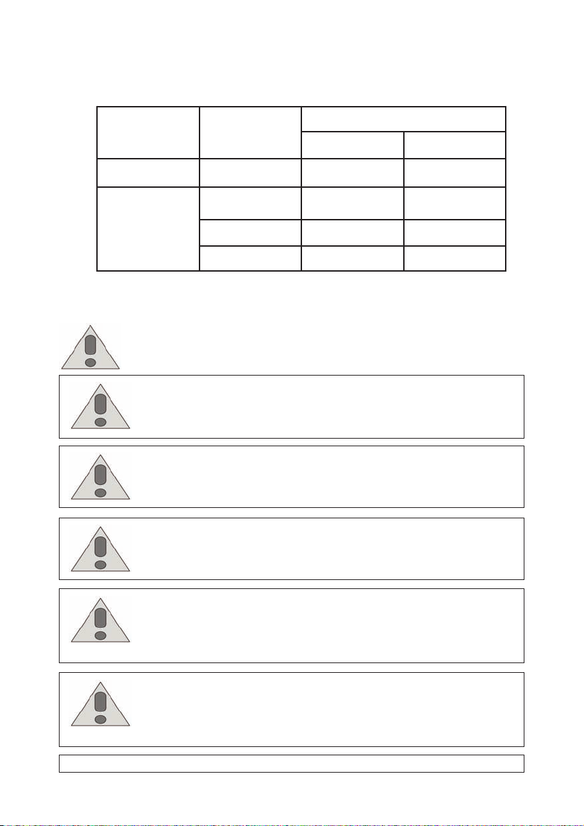
Working Pressure & Temperature Limits
(Solder Type Limits Per ASTM Std. B16.18-1979)
FLOW-CONTROL
STYLE
NPT
SWEAT
SAFETY INSTRUCTION
This safety alert symbol will be used in this manual to draw attention to safety
related instructions. When used, the safety alert symbol means.
ATTENTION! BECOME ALERT! YOUR SAFETY IS INVOLVED! FAILURE TO
FOLLOW THESE INSTRUCTIONS MAY RESULT IN A SAFETY HAZARD.
CAUTION:
proper application, installation, and maintenance of systems in accordance
with all applicable codes and ordinances.
CAUTION: If the DISCAL valve is not installed, commissioned and
maintained properly, according to the instructions contained in this
manual, it may not operate correctly and may endanger the user.
TYPE OF
SOLDER
-
95-5
Tin-Antimony
50-50 tin-Lead 125 150
60-40 tin-Lead 75 250
All work must be performed by qualified personnel trained in the
MAXIMUM LIMITATIONS
PRESSURE PSI TEMPERATURE °F
150 250
150 250
CAUTION: Make sure that all the connecting pipework is water tight.
CAUTION: When making the water connections, make sure that the
pipework connecting the DISCAL is not mechanically over-stressed. Over
time this could cause breakages, with consequent water losses which, in
turn, could cause harm to property and/or people.
CAUTION: Water temperatures higher than 100°F (38°C) can be
dangerous. During the installation, commissioning and maintenance of the
DISCAL valve, take the necessary precautions to ensure that such
temperatures do not endanger people.
Leave this manual for the user.
2
Page 3

2
G (m
3
/h) (gpm)
0,5
(
mm wtr
)
10
1
5
0,6
0,7
0,8
0,9
1,2
1,4
1,6
1,8
2,533,544,5
678
9
12141618254045
20
30
35
50
3/4"
1"
1 1/4"
1 1/2"
2” Steel
2 1/2”
100
607080
90
3”
4”
3/4" C
120
140
160
180
200
5”
6”
2”
0.
1
0.
05
0.09
0.08
0.07
0.06
0.035
0.04
0.045
0.12
0.14
0.16
0.18
0.25
0.3
0.35
0.
2
1
00
1
0
2
0
5
0
90
80
70
60
12
14
16
18
25
30
35
40
45
120
140
160
180
250
300
200
1
0.
5
0.9
0.8
0.7
0.6
0.45
0.4
9
8
7
6
0.025
0.03
0.02
(
ft of wtr
)
∆
P (
ft of wtr
)
100
2
10520
50
10
0
0
200
500
0.
1
0.
05
0.09
0.08
0.07
0.06
0.035
0.04
0.045
0.12
0.14
0.16
0.18
0.25
0.3
0.35
0.
2
1
0.
5
0.9
0.8
0.7
0.6
0.45
0.4
0.025
0.03
0.02
678
9
1214161825
3
0
35
4045
60708090
120
140
160
180
250
400
45
0
300
35
0
600
7008
00900
3
3.544.5
2.5
Hydronic characteristics
Optimal
(4.0 f/s)
FLOW CAPACITY
BRASS STEEL
3/4” C
6.0
1.4
14.3
3.2
11.6
3/4”
8.0
1.4
19.0
4.3
19.1
1”
9.3
2.1
22.1
5.0
32.5
1 1/4”
15.3
3.5
36.4
8.3
56.4
1 1/2”
23.9
5.4
56.8
12.9
73.1
2”
36.1
8.2
86.0
19.5
81
2”
37.3
8.5
88.8
20.2
87
2 1/2”
63.0
14.3
150.1
34.1
174
3”
95
21.7
227.4
51.6
208
4”
149
33.9
355.3
80.7
324
5”
259
58.8
616.4
140.0
520
6”
380
86.2
903.6
205.2
832
Size
GPM
m
3
/h
GPM
m
3
/h
Cv
Max.
(10.0 f/s)
The fluid velocity at connections for Discal 551 series air separators is
recommended to not exceed 10.0 f/s. Above this speed, heavy internal
turbulance and noise can occur and air elimination efficiency begins to fall
measurably. Optimal air elimination performance occurs at fluid velocities of
4.0 f/s or less. See the flow capacity chart.
3
Page 4

Installation
CHILLER
DISCAL units may be used in both heating and cooling systems, to ensure the
progressive removal of air which is continuously formed. The units should
preferably be installed after the boiler and on the pump suction side, as these are
the points where the formation of micro-bubbles is greatest. DISCAL air separators
must be installed vertically. In installation conditions where inspection is not
possible, it is recommended that the venting valve cap is replaced by a Caleffi
part number R59681 hygroscopic safety cap.
4
Page 5

Construction details
DISCAL devices are constructed in such a way as to allow maintenance and
cleaning operations to be carried out without having to remove the valve body
from the pipework. All valves are fitted with a bottom connection for installing a
drain valve. All internal air release control components are fully accessible in all
the models.
The automatic air release valve, located at the top of the units, has a long
chamber for the movement of the float. This feature prevents any debris present
in the water from reaching the sealing seat.
-
The moving parts
control the air venting
accessed
removing
the upper cover.
that
are
simply by
-
When cleaning, simply
unscrew the portion of the
body containing the
automatic air vent valve.
Code 59829
Replacement
Code 59756
5
Page 6

The air eliminators with flanged
A
B
CALEFFI
connections have an integral drain
point (A), which has two functions:
1. To aid the removal of air while
filling the system during the
commissioning stage.
2. To aid the removal of any debris
that may float within the air
eliminator.
A 1/2" drain port fitted to the base of
the device (B) provides the capability
to remove any debris that has settled
at the bottom of the air eliminator with
drain valve part number 538402 FD.
Accessories
Check valve code 561402A for expansion tanks. 1/2” NPT connections.
Hygroscopic safety vent cap code R59681.
Small anti-vacuum vent cap code 562100.
Replacement Discal air vent cap code 59119.
Caleffi North America, Inc.
3883 West Milwaukee Road
Milwaukee, WI 53208
T: 414.238.2360 F: 414.238.2366
 Loading...