

Page 1
38804.04
www.caleffi.com
SEP4™ combination hydraulic, air, dirt and magnetic
separator
© Copyright 2018 Caleffi
Installation, commissioning and servicing instructions
Function
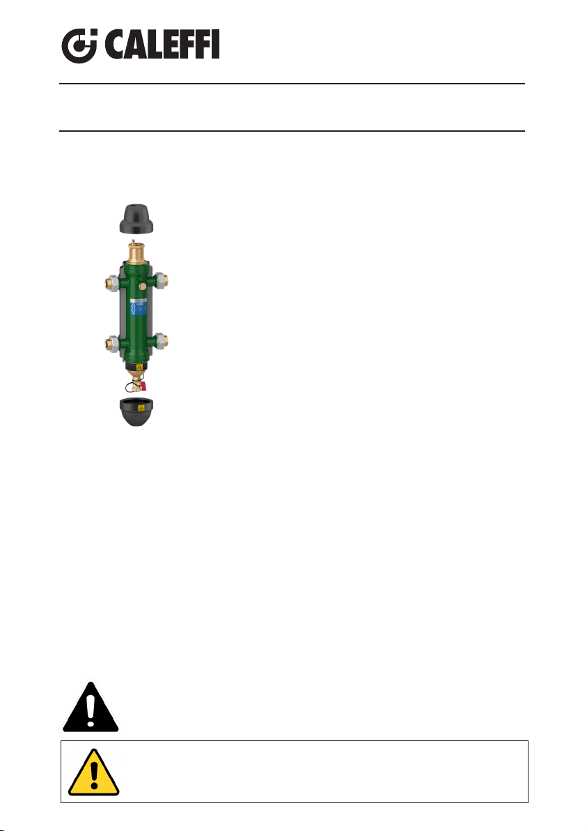
The Caleffi SEP4™ combination separator is a device that
incorporates four critical functions for hot or chilled water systems. It combines high performance air and dirt (magnetic and
non-magnetic) removal into the hydraulic separation function
which makes the primary and secondary circuits connected to
it hydraulically independent. The SEP4™ features an internal
coalescing element that continuously and automatically eliminates
air micro-bubbles with the simultaneous removal of dirt particles
as tiny as 5 microns. The air discharge capacity is very high, with
the capability of automatically removing all the air present in the
system down to the micro-bubble level. The 4-in-1 high performance functionality of the SEP4™ saves system installation and
maintenance costs as there is no need to include separate air
and dirt separators. In addition to removing solid impurities in the
system without isolating the separator or shutting down the system, the added powerful removable external magnet belt (union)
or probe(s) (flanged) in the lower body removes up to 100% of the
ferrous impurities, including magnetite, that can form in a hydronic
system. The SEP4™ has 2½ times the ferrous impurities removal
performance of standard air and dirt separators.
These items are designed for use in closed hydronic systems. Do not use in plumbing applications. These
items do not meet the low-lead plumbing standards of U.S. and Canada.
Product range
54950 series SEP4™ hydraulic, air, dirt and magnetic separator in steel with union connections,
drain and insulation: connections 1", 1¼", 1½", 2" NPT female union
54956 series SEP4™ hydraulic, air, dirt and magnetic separator in steel with union connections,
drain and insulation: connections 1", 1¼", 1½", 2" press union
54959 series SEP4™ hydraulic, air, dirt and magnetic separator in steel with union connections,
drain and insulation: connections 1", 1¼", 1½", 2" sweat union
5495 Series
SAFETY INSTRUCTION
This safety alert symbol will be used in this manual to draw attention to safety
related instructions. When used, the safety alert symbol means.
ATTENTION! BECOME ALERT! YOUR SAFETY IS INVOLVED! FAILURE
TO FOLLOW THESE INSTRUCTIONS MAY RESULT IN A SAFETY
HAZARD.
WARNING: This product can expose you to chemicals including lead, which is known
to the State of California to cause cancer and birth defects or other reproductive harm.
For more information go to www.P65Warnings.ca.gov.
1
Page 2
CAUTION: All work must be performed by qualified personnel
trained in the proper application, installation, and maintenance of
systems in accordance with all applicable codes and ordinances.
CAUTION: If the SEP4™ is not installed, commissioned and
maintained properly, according to the instructions contained
in this manual, it may not operate correctly and may endanger the user.
CAUTION: Make sure that all the connecting pipework is water tight.
CAUTION: When making the water connections, make sure
that the connecting pipework is not mechanically over-stressed.
Over time this could cause breakages, with consequent water
losses which, in turn, could cause harm to property and/or people.
CAUTION: Water temperatures higher than 100°F (38°C) can be
dangerous. During the installation, commissioning and maintenance
of the hydraulic separator, take the necessary precautions
to ensure that such temperatures do not endanger people.
Leave this manual for the user
Technical specications
Materials - body: epoxy resin coated steel
- air vent body: brass EN 12165 CW617N
- air vent hydraulic seal: peroxide-cured EPDM
- air vent float: PP
- air vent float linkages: stainless steel
- air vent float guide pin: stainless steel
- internal element: HDPE
- drain valve body: brass EN 12165 CW617N
- magnet: neodymium rare-earth
- insulatoin: closed-cell expanded PE-X
Performance
Suitable fluids: . water, glycol solution
Max. percentage of glycol: . 50%
Max. working pressure: 150 psi (10 bar)
Temperature range: without insulation 32–230°F (0 –110°C)
with insulation 32–210°F (0 –100°C)
Particle separation capacity: to 5 µm (0.2 mil)
Air sepration efficiency: 100% removal to microbubble level
Ferrous impurities separation efficiency: up to 100% removal
Connections
Main connections: 1", 1¼", 1½", 2" NPT female with unions
1", 1¼", 1½", 2" press with unions
Thermowell tap connection: ½" F straight thread
Lay length (press connection):
size 1 inch: 8¾"; size 1¼ inch: 9¾"; size 1½ inch: 11
Drain valve: ¾" garden hose connections
1", 1¼", 1½", 2" sweat with unions
5
⁄8"; size 2 inch: 12½"
2
Page 3
Technical specications of insulation
Material: closed-cell expanded PE-X
Thickness: 13/16" (20 mm)
Density: - inner part: 1.9 lb/ft3 (30 kg/m3)
- outer part: 5.0 lb/ft3 (80 kg/m3)
Conductivity (ISO 2581): at 32°F (0°C); .16 BTU/in (0.038 W/(m·K)
at 105°F (40°C); .26 BTU/in (0.045 W /(m·K)
Water vapor resistance coefficient (DIN 52615): > 1,300
Temperature range: 32–212°F (0–100°C)
Fire resistance (DIN 4102): class B2
Insulation
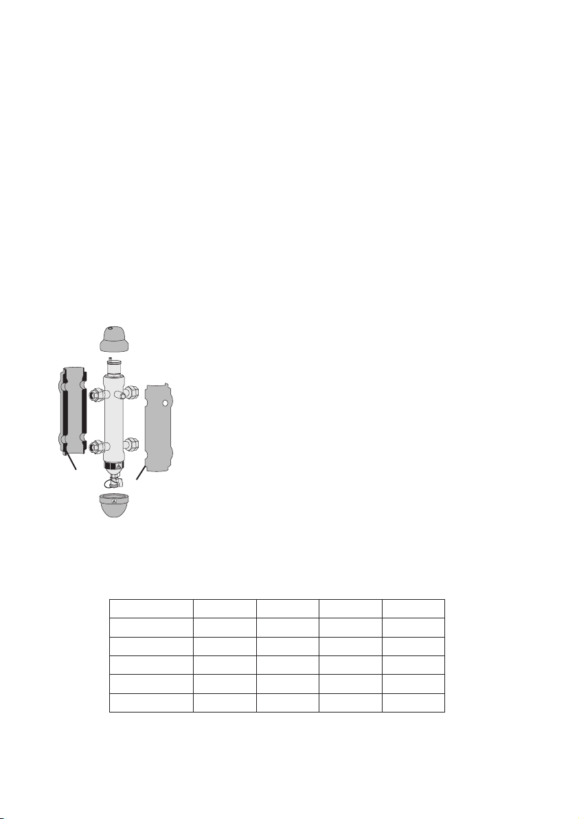
The SEP4™ comes standard with a preformed insulation shell. Theinsulation is made of a shell in
closed-cell expanded PE-X foam. This insulation ensures not only perfect heat insulation but also the
tightness required to prevent atmospheric water vapors from entering the unit. Forthese reasons,
this type of insulation can also be used in cooling water circuits, as it prevents the formation of condensate on the surface of theseparatorbody.
Procedure for installation and insulation assembly
1. Remove the two black head covers at the ends.
2. Open the two side sections.
3. Install the separator in the system.
4. For cooling applications, consider using a silicon caulk or sealant
by spreading a thin layer of sealant over the surfaces A and B. Wait
for solvent to evaporate (approx. 10 minutes). Note that once the
sealant dries it may be difficult to remove the insulation shell in the
future without destroying portions of the insulation.
A
5. Reassemble the two side sections.
B
6. Finish the assembly with adhesive tape (not supplied).
7. Complete by assembling back in place the two black head covers.
Hydraulic characteristics
The SEP4™ should be sized according to the maximum flow rate at the inlet. The selected value is
the primary circuit flow rate, or secondary circuit flow rate, whichever is largest.
Size 1" 11⁄4" 11⁄2" 2"
gpm 11 18 26 37
m3/h 2.5 4.0 6.0 8.5
l/s 0.7 1.1 1.6 2.3
Gallons 0.5 0.7 1.3 3.5
liters 2.0 2.6 5.0 13.2
3
Page 4
Installation
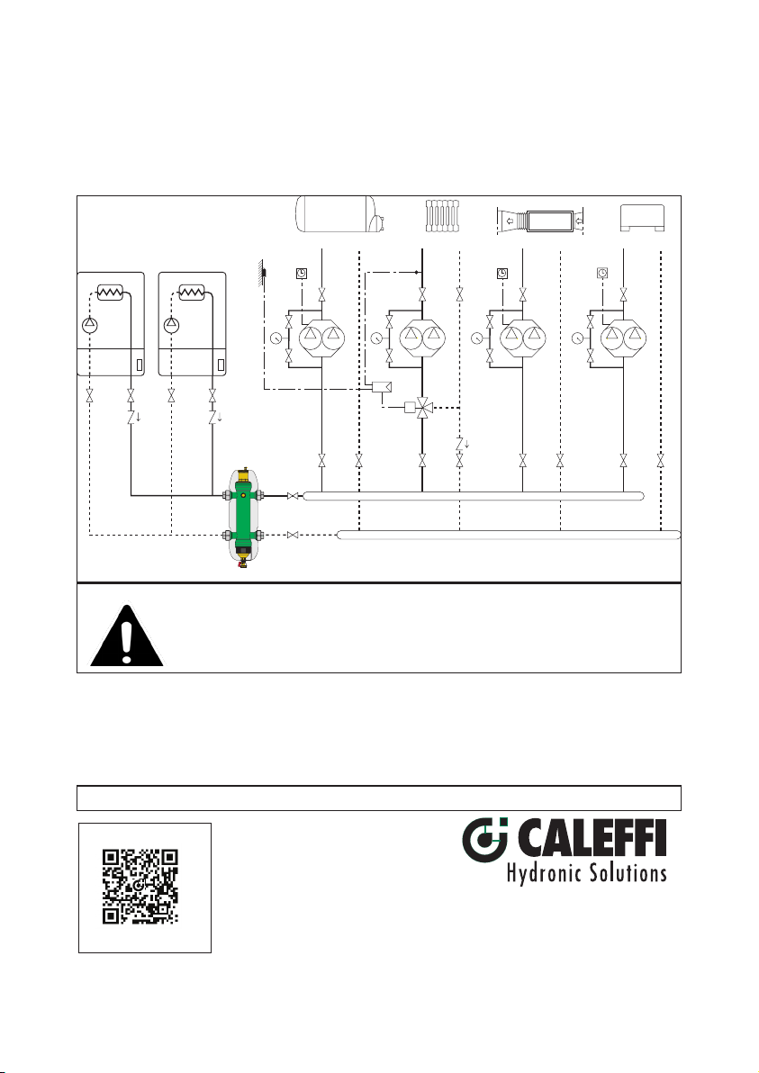
The SEP4™ should be installed only by qualified personnel in accordance with current local codes
and legislation. The SEP4™ is installed between the primary and secondary circuits, always in a
vertical position.
CAUTION: Corrosion or leakage can cause damage or injury. Periodically
inspect for signs of corrosion or leakage. If corrosion or leakage is noted,
the vent must be replaced. Failure to follow these instructions could result in
property damage and/or personal injury.
Service instructions
There is no service required for the SEP4™ combination air, hydraulic, dirt and magnetic separator.
Leave this manual at the service of users for their use
Scan to view
·
548, 549 & 5495
Caleffi North America, Inc.
3883 W. Milwaukee Road
Installation Tip
Milwaukee, WI 53208
T: 414.238.2360 F: 414.238.2366
7-19-18
4
 Loading...