

Page 1
www.caleffi.com
CALEFFI
Hydro Separator
38505.05
© Copyright 2018 Caleffi
Function
The hydraulic separator is a device which makes the primary and
secondary circuits connected to it independent, and can be
used on hot or chilled water systems.
The separator is supplied with an air-vent and check valve
assembly to permit automatic discharge of the air in the circuits,
and a drain valve for removing any impurities deposited in the
bottom of the unit.
These items are designed for use in closed hydronic systems.
Do not use in plumbing applications. These items do not meet
the low-lead plumbing standards of U.S. and Canada.
Product range
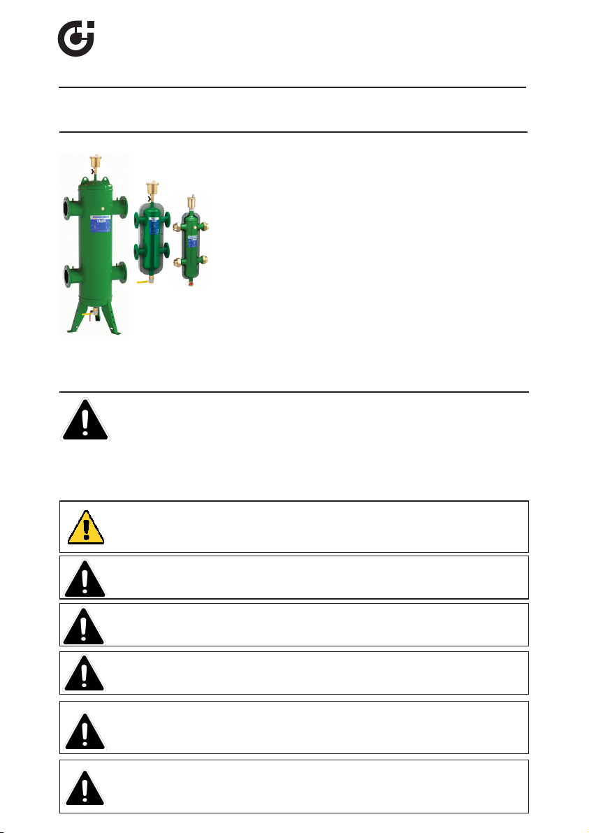
Series 548 Sizes:
Series NA548 Sizes:
8”-14” flanged connections ANSI 150 CLASS (ASME), with floor supports
SAFETY INSTRUCTION
This safety alert symbol will be used in this manual to draw attention to safety related
instructions. When used, the safety alert symbol means ATTENTION! BECOME ALERT!
YOUR SAFETY IS INVOLVED! FAILURE TO FOLLOW THESE INSTRUCTIONS MAY
RESULT IN A SAFETY HAZARD.
WARNING: This product can expose you to chemicals including lead, which
is known to the state of California to cause cancer and birth defects or other
reproductive harm. For more information go to www.P65Warnings.ca.gov.
1”, 1 1/4”, 1 1/2”, 2” NPT female union connections
1”, 1 1/4”, 1 1/2", 2" sweat union connections
1”, 1 1/4”, 1 1/2", 2" press union connections
2”- 4” flanged connections ANSI 150 CLASS
2”-6” flanged connections ANSI 150 CLASS (ASME)
548 Series
CAUTION: All work must be performed by qualified personnel trained in the
proper application, installation, and maintenance of systems in accordance
with all applicable codes and ordinances.
CAUTION: If the hydronic separator is not installed, commissioned and
maintained properly, according to the instructions contained in this
manual, it may not operate correctly and may endanger the user.
CAUTION: Make sure that all the connecting pipework is water tight.
CAUTION: When making the water connections, make sure that the
hydronic separator connecting pipework is not mechanically overstressed. Over time this could cause breakages, with consequent water
losses which, in turn, could cause harm to property and/or people.
CAUTION: Water temperatures higher than 100°F (38°C) can be
dangerous. During the installation, commissioning and maintenance of the
hydronic separator, take the necessary precautions to ensure that such
temperatures do not endanger people.
Page 2

Technical specifications of hydronic separator
Union connections
Separator:
1”, 1 1/4”, 1 1/2”, 2” NPT Female union
1”, 1 1/4”, 1 1/2”, 2” sweat union
1”, 1 1/4”, 1 1/2”, 2” press union
Drain valve:
Materials: - Separator body:
- Unions:
- Air vent body:
- Air vent hydraulic seal:
- Air vent float:
- Shut-off and drain valve body
Epoxy resin painted steel
3/4” NPT Male
Brass
Brass
peroxide-cured EPDM
PP
Brass
Medium: Water and non-hazardous glycol solutions up to 50%
Max operating pr
essure:
Temperature range:
Temperature gauge front connection:
Flanged connections
Separator:
150 psi (10 bar)
32 - 250°F (0÷120°C)
1/2”
2”- 4” ANSI 150 CLASS
2”- 14” ANSI 150 CLASS (ASME)
Air vent relief:
Drain valve:
Materials: - Separator body:
- Air vent body:
- Shut-off and drain valve body:
- Air vent seal:
- Air vent float:
Epoxy resin painted steel
3/8” Female
1 1/4” NPT Female
Brass
Brass
VITON
Stainless steel
Medium:Water and non-hazardous glycol solutions up to 50%
Max operating pressure: 150 psi (10 bar)
Temperature range:
32 - 250°F (0 - 120°C)
Technical
specifications
of insulation on union models
Inner part
Material: Closed-cell expanded PE-X
Thickness: 13/16” (20 mm)
Density: Inner part; 1,9 lb/ft
Outer part; 3,1 lb/ft
3
(30 kg/m3)
3
(50 kg/m3)
Conductivity (ISO 2581): - at 32°F (0°C); .16 BTU/in (0.038 W/(m·K)
- at 105°F (40°C); .26 BTU/in (0.045 W/(m·K)
Water vapour resistance coefficient (DIN 52615):
> 1.300
Temperature range:
Fire resistance (DIN 4102):
Technical
specifications
of insulation on flanged models (only for
0 - 210°F (0 - 100°C)
Class B2
2” to 4” sizes)
Inner part
Material:
Thickness:
Density:
Conductivity (ISO 2581):
Temperature range:
part
Outer
Material:
Thickness:
Fire resistance (DIN 4102):
rigid closed cell expanded polyurethane foam
2 3/8” (60 mm)
3 lb/ft3 (45 kg/m3)
0.16 BTU/in (0.023 W/(m·K)
32 - 220°F (0 - 105°C)
Embossed aluminium
7-mil (0.70 mm)
Class 1
Head covers
Heat formed material:
PS
Page 3
Hydraulic
characteristics
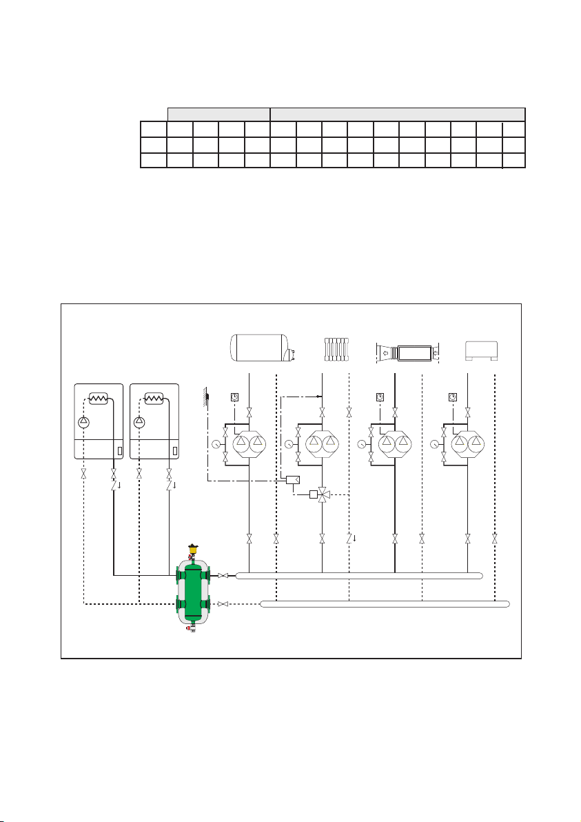
The hydraulic separator should be sized according to the maximum flow
rate value foreseen at the inlet. The selected value must be either that of
the primary circuit or of the secondary, whichever is the greatest.
UNION FLANGED
Size
gpm
m3/h
1 1/4” 1 1/2”
1”
2”
2”
3” 4” 5” 6” 8” 10” 12”
2 1/2”
11 18 26 37 60 80 124 247 300 484 792 1330 1850
2.5 4 68.4 13.6 18 28 56 68 110 180 302 420
14”
2500
568
Installation
The installation of hydraulic separator should only be done by qualified
personnel in accordance with current legislation.
The hydraulic separator is installed between the primary and secondary
circuits, always in a vertical position.
Page 4
Procedure for installation and insulation
assembly on union models
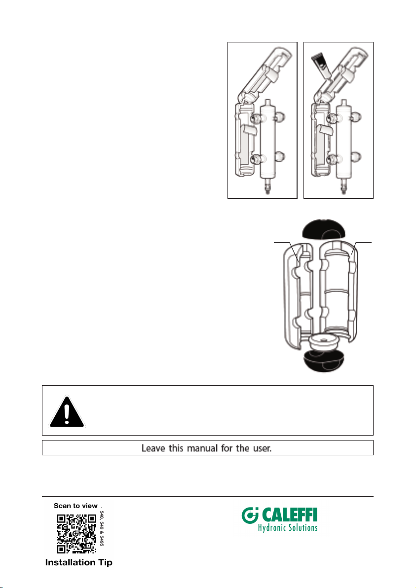
1.
Remove the protective strip from the adhesive
surface. Re-close the insulation shells.
2. If the hydraulic separator is used with chilled
water spread a thin layer of sealant on the edge
of the insulation and wait until the solvent
evaporates (10 minutes approx
it again.
Procedure for installation and insulation assembly
(only for 2” to 4” sizes)
1. Remove the two black head covers at the ends.
2. Open the two side sections and the lower cap.
3. Install the separator in the system.
4. Spread a thin layer of sealant over surfaces A and B.
Wait for the solvent to evaporate (approx. 10 minutes).
5. Reassemble the two side sections, fitting the lower cap into
one of the two sections and then connecting the other.
6. Finish the assembly with the adhesive tape provided in the box.
7. Complete with the two black head covers.
8. Fit the automatic air vent and the drain valve.
)
and the close
A
B
CAUTION:
Periodically inspect for signs of corrosion or leakage. If corrosion or
leakage is note, the vent must be replaced. Failure to follow these
instructions could result in property damage and/or personal injury.
Service Instructions
There is no service required for the hydraulic separator.
Corrosion or leakage can cause damage or injury.
7-19-18
Caleffi North America, Inc.
3883 West Milwaukee Road
Milwaukee, WI 53208
T: 414.238.2360 F: 414.238.2366
 Loading...