

Page 1
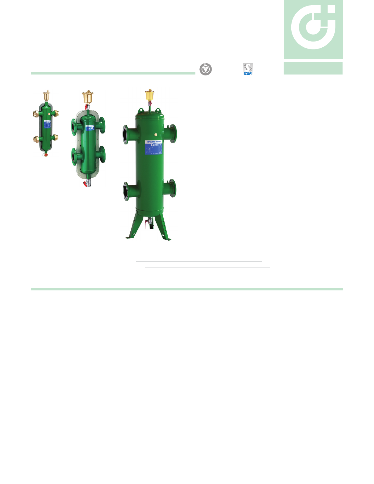
Hydro Separator
series 548
CALEFFI
Function
This device consists of several different functional components,
each of which meets specific requirements, typical of the circuits
used in heating and air-conditioning systems.
· Hydronic separator
To keep connected hydronic circuits totally independent from
each other.
· Dirt remover
To permit the separation and collection of any impurities present
in the circuits. Provided with a valved connection with discharge
piping.
· Automatic air vent valve
For automatic venting of any air contained in the circuits.
Provided with a valved connection for maintenance purposes.
Product range
Series 548 NPT F hydronic separator with insulation sizes 1”, 1
1/4
”, 1
1/2
” and 2” NPT F union
sizes 2”, 2
1/2
”, 3“ and 4” ANSI Flangenoitalusni htiw rotarapes cinordyh degnalF 845 seireS
Technical specification
R
E
G
I
S
T
E
R
E
D
BSI EN ISO 9001:2000
Cert. n° FM 21654
UNI EN ISO 9001:2000
Cert. n° 0003
01076/08 NA
Replaces 01076/06 NA
sizes 1” and 1
Series NA548 Flanged hydronic separator without insulation sizes 5”, 6”, 8”, 10” and 12” ASME ANSI Flange
*NA prefix indicates ASME tagged and registered with the National Board of Boiler and Pressure Vessel Inspectors
1/4
” sweat unionSeries 548 Sweat hydronic separator with insulation
Threaded and sweat union connections
Materials: - Body: epoxy resin painted steel
- Drain and shut-off valve: brass
- Air vent body: brass
Suitable fluids: water, glycol solution
Max percentage of glycol: 50%
Max working pressure: 150 psi (10 bar)
Temperature range: - with insulation: 32÷210°F (0÷100°C)
- without insulation: 32÷250°F (0÷120°C)
Connections: - Main: 1” & 1 1/4“ sweat & NPT and 1 1/2” & 2” NPT union
- Drain: 3/4“ hose
- thermometer pocket: 1/2“
Flanged connections
Materials: - Body: epoxy resin painted steel
- Drain and shut-off valve brass
- Air vent body brass
Suitable fluids: water, glycol solution
Max percentage of glycol: 50%
Max working pressure: 150 psi (10 bar)
Temperature range: - with insulation: 32÷220°F (0÷105°C)
- without insulation: 32÷250°F (0÷120°C)
Connections: - Flanged: 2” ÷ 12” ANSI 150 CLASS
- Drain: 1 1/4” & 2” NPT F
Technical specifcation of insulation for union connection versions
- Material: double density closed cell expanded PEX
- Thickness: 3/4” (20 mm)
- Density: - internal part: 2 lb/ft (30 kg/m3)
- external part: 3 lb/ft (50 kg/m3)
- Thermal conductivity: 32ºF (0°C): 9 BTU/in (0.038 W/m·K)
-40ºF (-40°C): 11 BTU/in (0.045 W/m·K)
- Coefficient of resistance to the diffusion of vapor: > 1.300
- Temperature range: 32-210ºF (0 -100ºC)
- Reaction to fire (DIN 4102) : class B 2
Technical specifcation of insulation for fanged versions up to 4”
Internal part
- Material: rigid closed cell expanded polyurethane foam
- Thickness: 2 3/8” (60 mm)
- Density: 3 lb/ft (45 kg/m3)
- Thermal conductivity: 6 BTU/in (0.023 W/m·K)
- Temperature range: 32-220 º F (0 – 105°C)
External cover
- Material: embossed aluminium
- Thickness: 7.0-mil (0.7 mm)
- Reaction to fire: class 1
Head covers
- Heat moulded material: PS
Page 2
Dimensions
AA
HYDRO-SEPARATOR
Serie 548
max
max
T
250°F
T
220°F
max
max
P
150 psi
P
D EC
150 psi
A
A
C D E
B
C
A
2”
2 1/2”
3”
4”
5”
6”
1 1/4"
1 1/4"
1 1/4"
1 1/4"
1 1/4"
1 1/4"
B
13”
13”
15”
15”
15”
15”
Code
548006A/96A
548007A/97A
548008A
1 1/4”
1 1/2”
548009A 2"
Code
548052A
B
8 3/4”
9 3/8”
10 7/8”
C
6 1/4”
7 3/8”
7 3/4”
10 1/8”
8 5/8”
9 1/2”
10 1/4”
11 7/8”
8”
8 3/8”
8 3/4”
9 1/2”
7.5
8.3
12.5
26.012”
(gal)
0.5
11
18
0.7
26
1.3
3.5
37
A
1"
Volume
Flow (gpm)
Weight (lb)
E
D
548062A
548082A
548102A
NA548120A*
NA548
NA548150A*
* without insulation
NA prefix indicates ASME tagged and registered with the National
Board of Boiler and Pressure Vessel Inspectors.
Add NA prefix to 2” to 4” flanged connection for ASME approved.
For larger ASME sizes consult with factory.
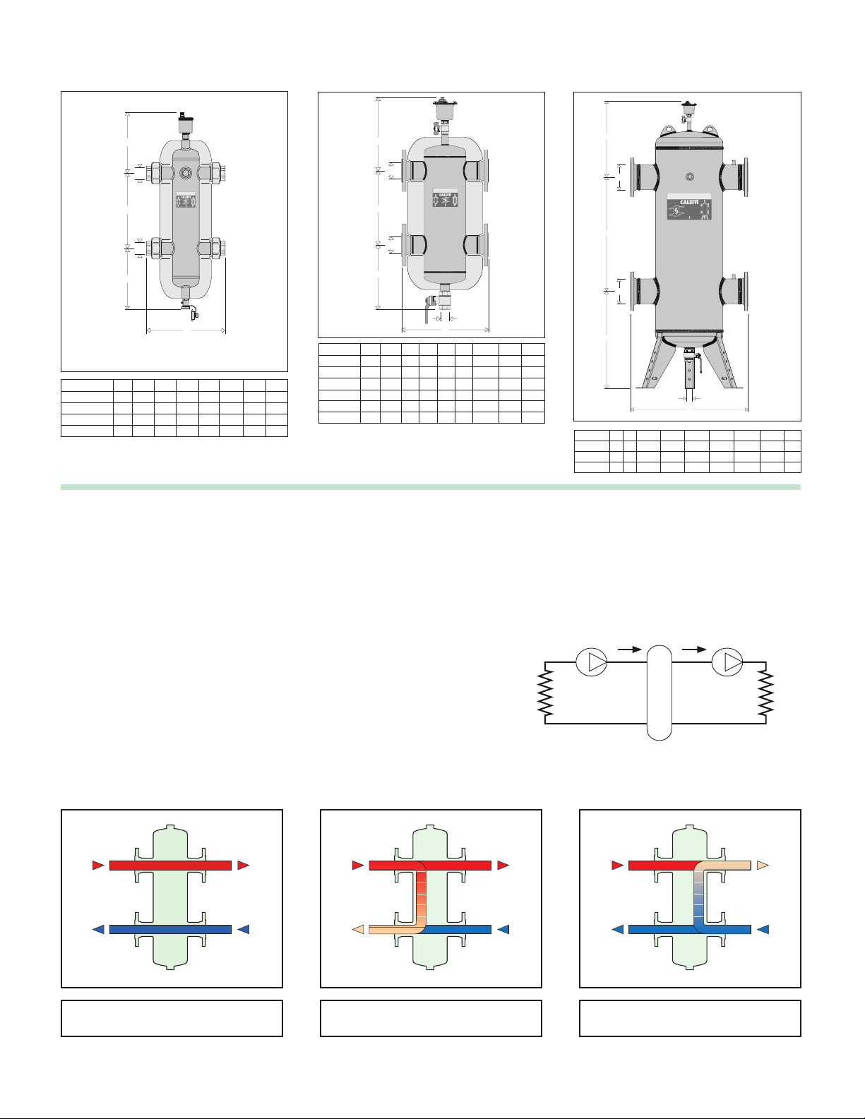
Operating principle
When a single system contains a primary production circuit, with its own
pump, and a secondary user circuit, with one or more distributions pumps,
operating conditions may arise in the system whereby the pumps interact,
creating abnormal variations in circuit flow rates and pressures.
The hydronic separator creates a zone with a low pressure loss, which
enables the primary and secondary circuits c on ne ct ed t o it t o be
hydraulically independent of each other;
the flow in one circuit does
not create a flow in the other if the pressure loss in the common
section is negligible.
HYDRO-SEPARATOR
Serie 548
T
250°F
T
220°F
max
max
P
150 psi
P
150 psi
max
max
HYDRO-SEPARATOR
Serie 548
T
250°F P
max
max
150 psi
C ED
AA
B
F
13”
13”
18”
18”
22”
22”
Weight (lb)
E
D
F
14”
14”
18”
18”
25”
25”
73
79
108
117
220
231
15”
15”
17”
17”
19”
19”
Flow (gpm)
40
80
124
247
300
484
Volume
4.0
4.0
8.0
8.0
22.5
23.2
(gal)
B
F
A
B
C
D
E
Code
NA548
NA548
NA548
200A
250A
300A
8”
2”
39
3/8
”
33
10”
2”
12”
2”
7/8
43
5/16
”
35
7/8
47
1/4
”
37
7/8
F
”
27
”
30”
”
31
Weight
1/2
”
35
1/2
”
41
3/4
”
1/2
”
47
3/4
”
1,100
When the secondary pump is off, there is no circulation in the secondary
circuit; the whole flow rate produced by the primary pump is by-passed
through the separator.
With the hydronic separator, it is thus possible to have a primary production
circuit with a constant flow rate and a secondary distribution circuit with
a variable flow rate; these operating conditions are typical of modern
heating and cooling systems.
Gp Gs
550
725
Flow
792
1,330
1,850
Volume
(gpm)(lb)
(gal)
95
175
255
In this case, the flow rate in the respective circuits depends exclusively
on the flow rate characteristics of the pumps, preventing reciprocal
influence caused by connection in series.
Therefore, using a device with these characteristics means that the flow
in the secondary circuit only circulates when the relevant pump is on,
permitting the system to meet the specific load requirements at that time.
Primary Secondary
G
primary
= G
secondary
sGpG
Primary Secondary
Gp Gs
G
primary
primary secondary
Three possible hydronic balance situations are shown below.
Primary Secondary
Gp Gs
> G
secondary
G
primary
< G
secondary
Page 3

Construction details
Isolating the air vent valve
In flanged separators, the air vent is
isolated manually, using a shut-off ball
valve. In union separators, however, the
air vent body is automatically isolated by
the check valve, which closes when the
air vent body is removed.
Dirt removing element
A vital function of the hydronic separator
is carried out by the dirt removing element
inside the device.This makes it possible
to separate and collect any impurities
which may be present in the system.
These impurities are removed by means
of the drain valve, which can be connected
to a discharge pipe, placed at the bottom
of the separator.
Insulation
Hydronic separators are available complete with a hot preformed
insulation shell. In the flanged series, u p to 4 ”, t he i ns ul at io n is
mad e of a shell in expanded polyurethane foam covered w ith a n
aluminium layer. In the threaded version the insulation is made of a
pre-formed shell in double density closed cell expanded PEX.
This insulation ensures not only perfect heat insulation but also the
tightness required to prevent atmospheric water vapors from entering
the unit. For these reasons, this type of insulation can also be used in
cooling water circuits, as it prevents the formation of condensate on the
surface of the separator body.
Hydraulic characteristics
The hydronic separator should be sized according to the maximum
flow rate value at the inlet.The selected design value must be the
greatest between the primary circuit and the secondary circuit.
Size Flow gpm (m
3
/h)
1” 11 (2.5)
1 1/4” 18 (4.0)
1 1/2”
26 (6.0)
Size Flow gpm (m3/h)
2” 40 (9)
2
1/2
” 80 (18)
3” 124 (28)
4” 247 (56)
5” 300 (75)
6” 484 (110)
Union connections
Flanged connections
Union connections Flanged connections
2” 37 (8.5)
8” 792 (180)
10” 1,330 (302)
12” 1,850 (420)
Page 4

Hydronic separator. Sweat and NPT connections with unions, 1” , 1 1/4“ , 1 1/2” , and 2” NPT . Epoxy resin painted steel body.
Temperature range 32 - 210°F (0 -100°C) with insulation or 32 - 250°F (0 -120°C) without insulation. Max. working
pressure 150 psi (10 bar). Supplied with: Automatic air vent valve 1/2” M connection with automatic check valve.
Brass body. Drain valve. Hose connection thread. Brass body. Pre-formed insulation shell is double density closed
cell expanded PEX.
SPECIFICATION SUMMARIES
Series 548
Hydronic separator. ANSI Flanged connections 2," 2 1/2", 3", 4", 5”, 6”, 8”, 10” and 12” . Epoxy resin painted steel body.
Temperature range of 32 - 220°F (0 -105°C) with insulation. Max. working pressure 150 psi (10 bar). Supplied with:
Automatic air vent with 3/8” F outlet connection and brass body. Brass body shut-off valve for air vent. Drain valve
brass body with 1 1/2” or 2” F connection. Rigid closed cell expanded polyurethane foam shell insulation with external
embossed aluminium cover. Sizes 5”, 6”, 8”, 10”, and 12” are ASME tagged and registered with the National Board of
Boiler and Pressure Vessel Inspectors, without insulation and temperature range of 32 - 250°F (0 -120°C).
Series 548
Application diagram
We reserve the right to change our products and their relevant technical data, contained in this publication, at any time and without prior notice.
CALEFFI
Caleffi North America, Inc.
3883 W. Milwaukee Rd. / Milwaukee, WI 53208
Tel: 414.238.2360 / Fax: 414.238.2366 / www.caleffi.us
© Copyright 2008 Caleffi North America, Inc.
 Loading...