

Page 1
www.caleffi.com
CALEFFI
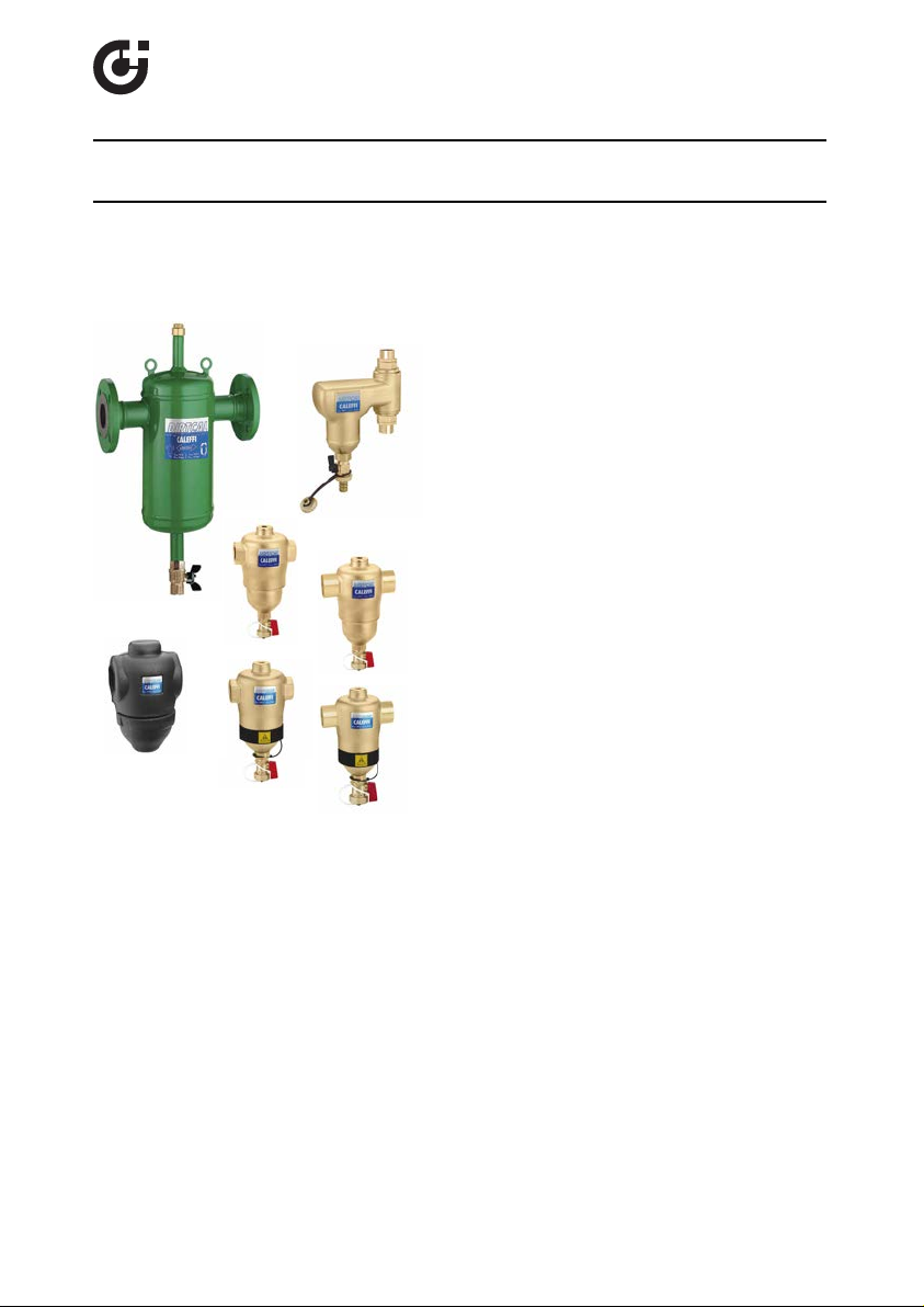
DIRTCAL®dirt separator
38643.05
© Cop y rig h t 2 0 12 Ca l ef f i
5462 - 5469 Series
Installation, commissioning and servicing instructions
Function
In heating and air conditioning control systems,
the circulation of water containing impurities may
result in rapid wear and damage to components
such as pumps and control valves. It also causes
blockages in the heat exchangers, heating
elements and pipes, resulting in a lower thermal
efficiency within the system. The dirt separator
separates off these dirt particles, which are mainly
made up of particles of sand and rust, collecting
them in a large collection chamber, from which
they can be removed even while the system is in
operation. This device is capable of efficiently
removing even the smallest particles, with
extremely limited head loss.
The sweat connection product is available in
versions for horizontal and vertical pipe
installations. The magnetic dirt separator is
available with NPT threaded or sweat connections
in versions for horizontal pipes only. Insulation
shells are available separately for field installation
for horizontal versions of the DIRTCAL®and
DIRTMAG®dirt separators.
Product range
5462 Series
5462 Series DIRTCAL dirt separator for horizontal pipes with sweat connections, sizes 1”–1
5463 Series DIRTMAG magnetic dirt separator for horizontal pipes with NPT threaded
5463 Series DIRTMAG magnetic dirt separator for horizontal pipes with sweat connections,
5465 Series Steel DIRTCAL dirt separator for horizontal pipes with ANSI flanged connections,
5469 Series DIRTCAL dirt separator for vertical pipes with sweat connections, sizes 3/4”–1”
NA5465 Series Steel DIRTCAL dirt separator for horizontal pipes with ANSI flanged connections
CBN5462 Series
DIRTCAL dirt separator for horizontal pipes with NPT threaded connections, sizes
3/4”–2”
1/4” - 1 1/2" - 2"
connections, sizes 1”–2”
sizes 1”–2”
sizes 2"–4"
(ASME and CRN Registered), sizes 2"–2 1/2"–3"–4"–5”–6"
Insulation shells for DIRTCAL series 5462 and DIRTMAG series 5463, sizes 3/4"-2".
1
Page 2
SAFETY INSTRUCTION
This safety alert symbol will be used in this manual to draw attention to safety
related instructions. When used, the safety alert symbol means.
ATTENTION! BECOME ALERT! YOUR SAFETY IS INVOLVED! FAILURE TO
FOLLOW THESE INSTRUCTIONS MAY RESULT IN A SAFETY HAZARD.
CAUTION: All work must be performed by qualified personnel trained in the
proper application, installation, and maintenance of systems in accordance
with all applicable codes and ordinances.
CAUTION: If the DIRTCAL®dirt separator is not installed, commissioned
and maintained properly, according to the instructions contained in this
manual, it may not operate correctly and may endanger the user.
CAUTION: Make sure that all the connecting pipework is water tight.
CAUTION: When making the water connections, make sure that the
pipework connecting the DIRTCAL®is not mechanically over-stressed.
Over time this could cause breakages, with consequent water losses
which, in turn, could cause harm to property and/or people.
CAUTION: Water temperatures higher than 100°F (38°C) can be
dangerous. During the installation, commissioning and maintenance of the
DIRTCAL®dirt separator, take the necessary precautions to ensure that
such temperatures do not endanger people.
Leave this manual for the user
Technical specifications
Brass body dirt separators
Connections: - Main: 3/4”, 1”, 1 1/4”, 1 1/2”, 2” NPT female
- Top: 1/2” F (with plug)
- Drain: 3/4” garden hose connection
Materials: - Body, dirt collection chamber and top plug: brass
- Internal element: glass reinforced nylon PA66G30
- Hydraulic seal: EPDM
- Drain cock: brass
Suitable fluids: water, glycol solution
Max percentage of glycol: 50%
Max working pressure: 150 psi (10 bar)
Temperature range: 32–250°F (0–120°C)
Particle separation capacity: to 5 µm (0.2 mil)
2
1”–1 1/4” - 1 1/2" - 2" sweat
vertical: 3/4" - 1" sweat
vertical: hose connection
(stainlesss steel, 5469 series)
Page 3

Steel body dirt separators
(kPa)
1"
1 1/4"
1 1/2"
2”
2 1/2”3”4”
3/4"
5”
6”
2”
0.
1
0.
05
0.09
0.08
0.07
0.06
0.035
0.04
0.045
0.12
0.14
0.16
0.18
0.25
0.3
0.35
0.
2
1
0
.1
0
0.2
0
0.5
0.9
0.8
0.7
0.6
0.12
0.14
0.16
0.18
0.25
0.3
0.35
0.4
0.45
1.2
1.4
1.6
1.8
2.5
3
2.0
1
0.
5
0.9
0.8
0.7
0.6
0.45
0.4
0.09
0.08
0.07
0.06
0.025
0.03
0.02
(
ft of water
)
∆p(ft of water
)
100
2
10
5
20
50
1000
200
500
0.
1
0.
05
0.09
0.08
0.07
0.06
0.035
0.04
0.045
0.12
0.14
0.16
0.18
0.25
0.3
0.35
0.
2
1
0.
5
0.9
0.8
0.7
0.6
0.45
0.4
0.025
0.03
0.02
678
9
1214161825
3
0
35
4045
60708090
120
140
160
180
250
400
45
0
300
35
0
600
7008009
00
3
3.544.5
2.5
BRASS BODY
STEEL BODY
G (l/s) (gpm)
2
0.5
10
1
5
0.6
0
.70.80.91.2
1
.4
1
.6
1
.82.5
3
3
.5
4
4
.5
678
9
12141618254045
20
30
355060
70
0.25
0.40
0.45
0.20
0.30
0.35
3/4" - 1”
Vertical
Connections: - Main: 2", 2 1/2", 3", 4", 5”, 6" ANSI B16.5 150 CLASS RF
Flanged (ASME & CRN registered)
2", 2 1/2", 3", 4" ANSI B16.5 150 CLASS RF Flanged
- Top: 3/4” M (with plug)
- Drain: 1” NPT
Materials: - Body: epoxy resin painted steel
- Int. element: stainless steel
- Hydraulic seal: non-asbestos fiber
- Drain cock: brass
Suitable fluids: water, glycol solution
Max percentage of glycol: 50%
Max working pressure: 150 psi (10 bar)
Temperature range without insulation: 32–250°F (0–120°C)
Particle separation capacity: to 5 µm (0.2 mil)
Hydraulic characteristics
3/4”
18.8
3/4”-1” *
19.91”32.6
Size
Cv
* Vertical versions
The maximum fluid velocity recommended at the unit connections is~4 f/s.
The following table shows the maximum flow rates to comply with this condition.
3/4”
6
0.4
3/4”-1” *
9.0
0.57
Size
gpm
l/s
* Vertical versions
BRASS BODY STEEL BODY
BRASS BODY STEEL BODY
1”
9.3
0.6
1 1/4”
56.6
1 1/4”
15.3
1.0
1 1/2”
73.3
1 1/2”
23.9
1.5
2”882 1/2”
2”
81
2”
2”
37
36
2.35
2.28
3
1763”2114”3285”520
2 1/2”
62
3.9
3”
4”
94
148
5.9
9.3
5”
259
16.3
6”
842
6”
376
23.7
Page 4

CHILLER
Tmax110∞C
P
max10bar
Tmax105∞C
P
max10bar
BI-DIRECTIONAL
Tmax 110∞C
P
max 10bar
Tmax 105∞C
P
max 10bar
BI-DIRECTIONAL
Tmax110∞C
P
max10bar
Tmax105∞C
P
max10bar
BI-DIRECTIONAL
Tmax110∞C
P
max10bar
Tmax105∞C
P
max10bar
BI-DIRECTIONAL
Installation
The dirt separator must always be installed in a vertical position, preferably on the return
circuit upstream of the boiler (or chiller). This enables it to intercept dirt particles already
present in the circuit, particularly when it is first started, before they reach the boiler (or chiller).
Flow direction for the DIRTCAL and DIRTMAG dirt separators is bi-directional; flow in either
direction is permitted.
4
Page 5

1
1
Draining off dirt
The dirt separator collection
chamber has a ball drain
cock. Using the handle
provided it is possible to drain
off the accumulated dirt
particles even with the system
in operation.
Procedure for removing insulation and draining dirt
particles in the DIRTMAG series 5463
WARNING: The symbol shown
on the removable ring indicates the
presence of magnets that generate a
strong magnetic field. This could cause
damages to electronic devices kept in
its proximity.
1. Remove the insulation by taking off
the bottom casing of the collection
chamber first, and if necessary, the
top insulation casing later.
2. Remove the magnetic ring
containing the two magnets, that
during operation attracted the
ferrous particles.
3. Flush out the ferrous and nonferrous
debris by turning the handle to open
the drain valve.
4. When finished, replace the insulation
shells.
Maintenance
To perform maintenance, simply use
a 26 mm hexagon wrench (1) to
unscrew the dirt collection chamber,
to which the inner mesh element is
connected for removal and for
cleaning.
5
Page 6

CALEFFI
Use of top connector
Tmax110∞C
P
max10bar
Tmax 105∞C
P
max10bar
BI-DIRECTIONAL
The connector on top of the dirt separator can be used for
optional installation of an automatic air vent valve, Caleffi code
C
502243A for the threaded or sweat versions- 5462 Series (A),
replacing the standard 1/2" NPT Male plug (pn NA10044).
Use Caleffi code 501502A for the flanged version 5465 Series (C)
-replacing the standard 3/4" NPT
End Cap (pn 41525).
Use bottom connector
The dir t separators come
complete with drain valves
A
B
installed on the bottom port:
Caleffi code 538402 FD for
horizontal
threaded or sweat
versions- 5462 series (A),
538400 for vertical versions5469 series, code NA39753 for
the flanged version - 5465
series (C).
Safety
The dirt separator must be installed by a licensed plumber in accordance with
national regulations and/or relevant local requirements.
Make sure that all connecting joints are water tight.
When making pipe connections take care not to damage the thread in the body of the valve by over
tightening. Take care not to apply too much force to the body of the valve when making pipe
connections.
Water temperatures greater than 120°F may cause serious burns. When installing, using and
maintaining dirt separators take appropriate measure to ensure that these temperatures do not
cause harm to persons.
Leave this manual at the service of users for their use
Caleffi North America, Inc.
3883 W. Milwaukee Road
Milwaukee, WI 53208
T: 414.238.2360 F: 414.238.2366
6
 Loading...