

Page 1
www.caleffi.com
CALEFFI
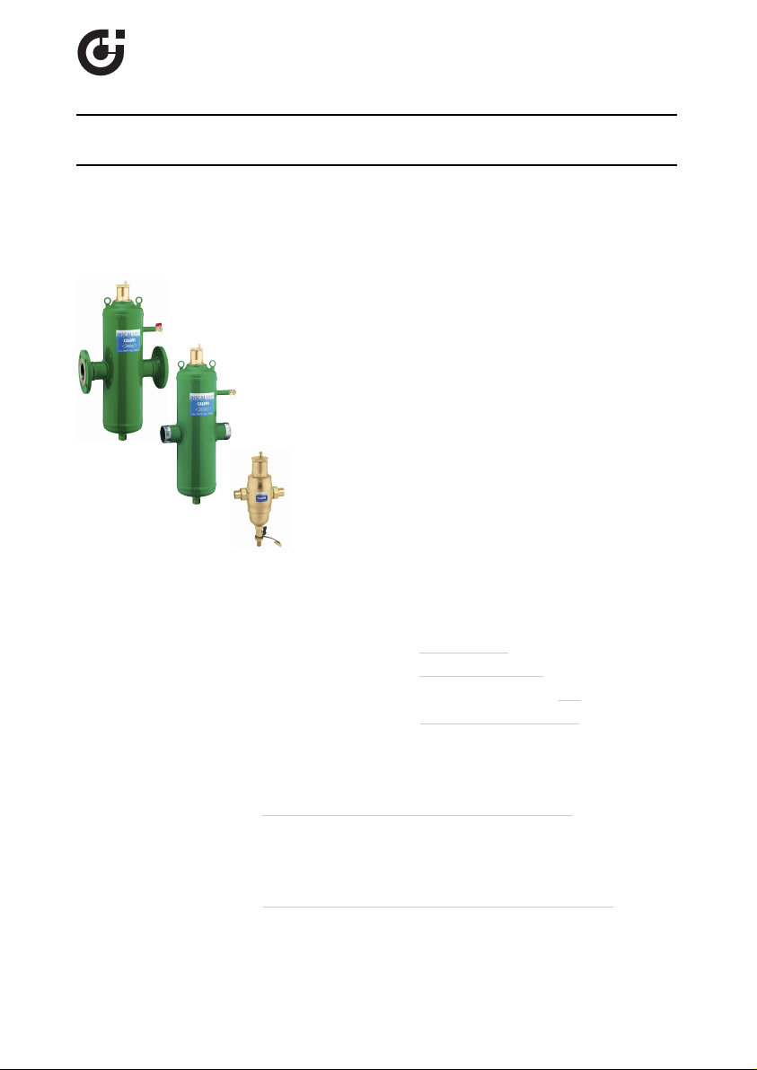
DISCALDIRT®air and dirt separator
Installation, commissioning and servicing instructions
Function
Air and dirt separators are used to continuously remove the
air and debris contained in the hydronic curcuits of heating
and cooling systems. The air discharge of these devices is
very high. They are capable of automatically removing all of
the air present in the system down to the micro-bubble level.
The DISCALDIRT
solid impurities in the system. The impurities collect at the
bottom of the device and can be removed through the drain
pipe for the steel versions, to which a separately sourced
drain valve can be mounted, or drain shut-off valve for the
brass version. The circulation of fully de-aerated and
cleaned water enables the equipment to operate under
optimum conditions, free from noise, corrosion, localized or
mechancial damage.
38557.02
546 Series
®
air and dirt separator also separates any
Product range
Series 546 DISCALDIRT air and dirt separator in brass Sizes 3/4” and 1” sweat union
Series 546 DISCALDIRT air and dirt separator in brass Size 1” NPT male union
Series 546 DISCALDIRT air and dirt separator in steel with flanged connections Sizes 2”–6” ANSI
Series 546 DISCALDIRT air and dirt separator in brass Size 1-1/4" sweat
Series NA546 DISCALDIRT air and dirt separator in steel with flanged connections
Series NA546 DISCALDIRT air and dirt separator in steel with threaded connections
designed and built in accordance with Section VIII, Division 1 of the
ASME Boiler and Pressure Vessel Code and tagged and registered
with the National Board of Boiler and Pressure Vessel Inspector;
CRN registered Sizes 2”–12” ANSI
designed and built in accordance with Section VIII, Division 1 of the
ASME Boiler and Pressure Vessel Code and tagged and registered
with the National Board of Boiler and Pressure Vessel Inspector;
CRN registered Sizes 2”–4”
1
Page 2

Technical specification
Brass DiscalDirt
Materials: - Body, Dirt separation chamber and Automatic air vent body: brass
Suitable fluids: water, glycol solution
Max percentage of glycol: 50%
Max working pressure: 150 psi (10 bar)
Temperature range: 32–230°F (0–110°C)
Particle separation capacity: to 5 µm (0.2 mil)
Connections: - Main: 3/4” and 1” sweat union; 1” NPT male union; 1 1/4” sweat
Steel DiscalDirt
Materials: - Body: epoxy resin painted steel
Suitable fluids: water, glycol solution
Max percentage of glycol: 50%
Max working pressure: 150 psi (10 bar)
Temperature range: 32–250°F (0–120°C)
Particle separation capacity: to 5 µm (0.2 mil)
Connections: - Flanged (ASME & CRN Registered): 2”–12” ANSI B16.5 150 CLASS RF
- Internal element: glass reinforced nylon, PA66GF30
- Float: PP
- Float guide and Stem: brass
- Float lever and Spring: stainless steel
- Seals: EPDM
- Drain shut-off valve: brass
- Drain shut-off valve: hose connection
- Automatic air vent body: brass
- Internal element: stainless steel
- Float: PP
- Float guide and Stem: brass
- Float lever and Spring: stainless steel
- Seals: EPDM
- Side drain shufoff valve: brass
- Flanged: 2”–6” ANSI B16.5 150 CLASS RF
- Threaded (ASME and CRN Registered): 2”–4”
- Drain pipe: 2”–6” : 1” NPT male
8”–12” : 2” NPT male
2
Page 3
SAFETY INSTRUCTION
This safety alert symbol will be used in this manual to draw attention to safety related
instructions. When used, the safety alert symbol means ATTENTION! BECOME ALERT!
YOUR SAFETY IS INVOLVED! FAILURE TO FOLLOW THESE INSTRUCTIONS MAY
RESULT IN A SAFETY HAZARD.
CAUTION: All work must be performed by qualified personnel trained in the
proper application, installation, and maintenance of systems in accordance
with all applicable codes and ordinances.
CAUTION:
commissioned and maintained properly, according to the instructions contained
in this manual, it may not operte correctly and may endanger the user.
CAUTION: Make sure that all the connecting pipework is water tight.
CAUTION: When making the water connections, make sure that the
pipework connecting the DISCALDIRT air and dirt separator mechanically
overstressed. Over time this could cause breakages, with consequent
water losses which, in turn, could cause harm to property and/or people.
CAUTION: Water temperatures higher than 100°F (38°C) can be
dangerous. During the installation, commissioning and maintenance of the
DISCALDIRT air and dirt separator, take the necessary precautions to
ensure that such Temperatures do not endanger people.
If the DISCALDIRT air and dirt separator is not installed,
Leave this manual for the user.
3
Page 4

Operating principle
The air and dirt separator uses the combined action of several physical principles. The active
part consists of an assembly of concentric metal mesh surfaces. These elements create the
whirling movement required to facilitate the release of micro-bubbles and their adhesion to these
surfaces.
The bubbles, fusing with each other, increase in volume until the hydrostatic thrust is such as to
overcome the adhesion force to the structure. They rise towards the top of the unit from which
they are released through a float-operated automatic air vent valve. When the impurities present
in the water collide with the metal surfaces of the internal element they become separated and
precipitate to the bottom of the separator body.
4
Page 5

0.56
G (l/s) (gpm)
(kPa)
2.8
1.4
0.33
0.39
0.44
0.50
0.69
0.83
0.97
1.1
1.25
1.7
1.9
2.2
2.5
3.3
3.9
4.4
5.0
6.9
11
12
5.6
8.3
9.7
14
2”
2 1/2”
28
171922
25
3”
4”
333944
50
56
5”
6”
0.1
0.05
0.09
0.08
0.07
0.06
0.035
0.04
0.045
0.12
0.14
0.16
0.18
0.25
0.3
0.35
0.2
1
0
.
1
0
.
2
0
.
5
0.9
0.8
0.7
0.6
0.12
0.14
0.16
0.18
0.25
0.3
0.35
0.4
0.45
1.2
1.4
1.6
1.8
2.5
3
2
1
0.5
0.9
0.8
0.7
0.6
0.45
0.4
0.09
0.08
0.07
0.06
0.025
0.03
0.
0
2
(ft of water)
∆
P
(ft of water)
100
10
5
20
50
1000
200
500
0.1
0.05
0.09
0.08
0.07
0.06
0.035
0.04
0.045
0.12
0.14
0.16
0.18
0.25
0.3
0.35
0.2
1
0.5
0.9
0.8
0.7
0.6
0.45
0.4
0.025
0.03
0.
0
2
678
9
1214161825
3
0
35
4
0
45
60708090
120
140
160
180
250
400
45
0
300
35
0
600
7008009
00
1.2
1.4
1.6
1.8
2
6
4.5
1.2
1.4
1.6
1.8
2
698397
111
125
2000
1200
1400
1600
1800
4
3.5
5
12”
10”
8”
4.3
4.0
3.5
3.0
2.7
2.2
0.27
0.25
0.22
0.19
0.17
0.14
1”
3/4”
1 1/4”
Optimal
(≤4.0 f/s)
FLOW CAPACITY
2”
37.3
2.4
88.8
5.6
87
2 1/2”
63.0
4.0
150.1
9.5
174
3”
95
6.0
227.4
14.3
208
4”
149
9.4
355.3
22.4
324
5”
259
16.3
616.4
38.9
520
6”
380
24.0
903.6
57.0
832
Size
GPM
l/s
GPM
l/s
Cv
Max.
(10.0 f/s)
8”
625
40.0
1,570
100.0
1,109
10”
980
62.0
2,450
155.0
1,387
12”
1,410
89.0
3,530
222.0
1,664
1 1/4”
10.0
0.63
25.0
1.6
40.0
3/4”
8.0
0.5
19.0
1.2
19.1
BRASS STEEL
1”
9.3
0.6
22.1
1.4
32.5
Hydraulic characteristics
Flow Capacity
The fluid velocity at connections for DISCALDIRT 546 and NA546 series air and dirt separators
is recommended to not exceed 10.0 f/s. Above this speed, heavy internal turbulence and
noise can occur and air and dirt elimination efficiency begins to fall measurably. Optimal air
and dirt separation performance occurs at fluid velocities of 4.0 f/s or less. See the flow
capacity chart.
5
Page 6

Installation
CHILLER
DISCALDIRT units may be
used in both heating and
cooling systems, to ensure
continuous air and dirt
elimination. The units should
be installed after the boiler
and on the pump suction
side, as these are the points
where the formation of
micro-bubbles is greatest.
DISCALDIRT air and dirt
separators must be installed
vertically. In installation
conditions where inspection
is not possible, it is
recommended that the
venting valve cap is
replaced by a Caleffi part
number R59681
hygroscopic safety vent.
The standard replacement
cap code number is 59199.
6
Page 7

Maintenance
3
1
2
4
5
2
1
3
4
8
7
6
The DISCALDIRT air and dirt separator is designed to be maintained and cleaned without
removing it from system piping.
The automatic air vent, located at the top of the device, has a long chamber for float movement
(2). This prevents any impurities in the water from reaching the seal seat. The non-corroding
stainless steel pinned linkage and PP float can be accessed by removing the upper cover (1). The
float guide pin (4) prevents the float from jamming against the inside housing in non-vertical
installations or from boiler
residue buildup. Unscrew the top
part of the casing (3) to clean the
entire air venting system.
The air venting system in both
brass and steel DISCALDIRT air
and dirt separators features a
pinned float. Steel DISCALDIRT
air and dirt separators with
flanged and threaded
connections have an integral
side drain port (5), which has two
functions:
1. Air removed while filling the
system during system
commissioning.
2. Remove debris that float
within the air separator.
A separately-sourced drain valve installed to the drain pipe at the base of the steel DISCALDIRT
air and dirt separator (8) can be used to remove any debris that has settled at the bottom of the
separator, even with the system is in operation.
To inspect the internal element of brass DISCALDIRT air and dirt separators, unscrew the large dirt
separation chamber (6) with a 26 mm hexagon wrench. The internal element can be removed for
cleaning. Additionally, the brass
air and dirt separator has a
lever-operated shut-off drain
valve and hose attachment with
plug (7), to drain accumulated
debris as needed.
7
Page 8

CALEFFI
Caleffi North America, Inc.
3883 W. Milwaukee Road
Milwaukee, WI 53208
T: 414.238.2360 F: 414.238.2366
 Loading...