

Page 1
www.caleffi.com
Scan to view
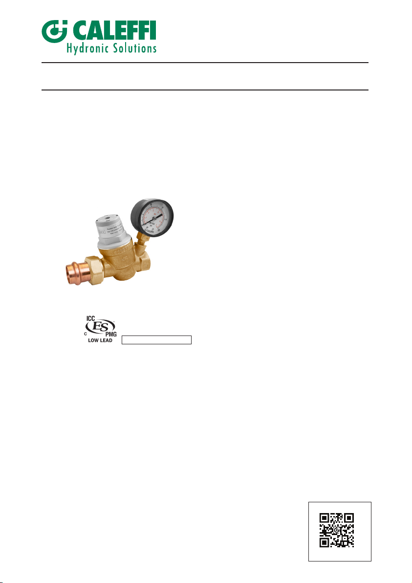
PresCal™ Compact pressure reducing valve
NA10617.02
© Copyright 2020 Caleffi
Installation, commissioning and servicing instructions
NSF/ANSI/CAN 61
533H Series
Function
Pressure reducing valves are devices which, when
installed on water systems, reduce and stabilize the
pressure of the water entering from the water supply
main. This pressure, in general, is too high and
variable for domestic systems to operate correctly.
PresCal™ Compact 533H series pressure reducing
valves, ideal for small system applications, is constructed
of a DZR low-lead forged brass body and incorporates a
unique noise reducing and high flow seat design. It can
be easily serviced with a replaceable cartridge and has
an integral stainless steel filter (35 mesh), suitable
for water systems that may contain sediment and
debris. A tamper-resistant cap is included to replace the
standard cap to hide the adjustment screw to prevent
set point tampering.
The valve complies with NSF/ANSI 61 (180°F/82°C
Commercial Hot) as certified by ICC-ES, and complies
with NSF/ANSI 372, low lead, and codes IPC, IRC, NPC
and UPC for use in accordance with the US and
Canadian plumbing codes, as certified by ICC-ES.
Product range
5333H Series
5336H Series
5337H Series
5338H Series
5339H Series
PresCal Compact pressure reducing valve with or without pressure gauge, connections
NPT female threaded union inlet and NPT female outlet...........................sizes ½" and
PresCal Compact pressure reducing valve with or without pressure gauge, connections
press union inlet and NPT female outlet................................................................sizes
PresCal Compact pressure reducing valve with or without pressure gauge, connections
PEX crimp union inlet and NPT female outlet........................................................sizes
PresCal Compact pressure reducing valve with or without pressure gauge, connections
PEX expansion union inlet and NPT female outlet.................................................sizes
PresCal Compact pressure reducing valve with or without pressure gauge, connections
sweat union inlet and NPT female outlet...................................................sizes ½" and
¾”
¾”
¾”
¾”
¾”
·
533H PresCal™ Compact
Installation Tip
1
Page 2
SAFETY INSTRUCTION
This safety alert symbol will be used in this manual to draw attention to safety related
instructions. When used, the safety alert symbol means.
ATTENTION! BECOME ALERT! YOUR SAFETY IS INVOLVED! FAILURE TO
FOLLOW THESE INSTRUCTIONS MAY RESULT IN A SAFETY HAZARD.
WARNING: This product can expose you to chemicals including lead, which is known
to the State of California to cause cancer and birth defects or other reproductive harm.
For more information go to www.P65Warnings.ca.gov.
CAUTION: All work must be performed by qualified personnel trained in the
proper application, installation, and maintenance of systems in accordance
with all applicable codes and ordinances.
CAUTION: If the PresCal 533H series compact pressure reducing valve is not
installed, commissioned and maintained properly, according to the instructions
contained in this manual, it may not operate correctly and may endanger the user.
CAUTION: Make sure that all the connecting pipework is water tight.
CAUTION: When making the water connections, make sure that the
connecting pipework is not mechanically over-stressed. Over time this could
cause breakages, with consequent water losses which, in turn, could cause
harm to property and/or people.
CAUTION: Water temperatures higher than 100°F (38°C) can be dangerous.
During the installation, commissioning and maintenance of the 533H PRV,
take the necessary precautions to ensure that such temperatures do not
endanger people.
Caleffi shall not be liable for damages resulting from stress corrosion, misapplication or misuse of it products.
Leave this manual for the user
2
Page 3
CONSIGNE DE SÉCURITÉ
Ce symbole d'avertissement servira dans ce manuel à attirer l'attention sur la
sécurité concernant instructions. Lorsqu'il est utilisé, ce symbole signifie.
ATTENTION! DEVENEZ ALERTE ! VOTRE SÉCURITÉ EST EN JEU ! NE
PAS SUIVRE CES INSTRUCTIONS PEUT PROVOQUER UN RISQUE DE
SECURITE.
AVERTISSEMENT:
plomb, qui est connu dans l’État de Californie pour causer le cancer, dommages à la
naissance ou autre. Pour plus d’informations rendez-vous www.P65Warnings.ca.gov.
ATTENTION: Tous les travaux doivent être effectués par du personnel
qualifié formé à la bonne application, installation et maintenance des systèmes
conformément aux codes et règlements locaux.
ATTENTION:
service et entretenu correctement, selon les instructions contenues dans ce manuel,
il peut ne pas fonctionner correctement et peut mettre en danger l'utilisateur.
ATTENTION: S'assurer que tous les raccordements sont étanches.
ATTENTION: Lorsque vous effectuez les raccordements d'eau, assurez-
vous que la tuyauterie reliant réducteur de pression n'est pas mécaniquement
des overstressed. Au fil du temps, ceci pourrait causer des ruptures, avec
pour consequence des pertes en eau qui, à leur tour, peuvent causer des
dommages à la propriété et/ou les gens.
ATTENTION: les températures de l'eau supérieure à 100°F (38°C) peut
être dangereux. Au cours de l'installation, mise en service et l'entretien de
le réducteur de pression, Série 533H, prendre les precautions nécessaires
afin de s'assurer que de tells températures ne compromettent pas les gens.
Ce produit peut vous exposer à des produits chimiques comme le
Si le réducteur de pression, Série 533H, n'est pas installé, mis en
LAISSEZ CE MANUEL AVEC L’UTILISATEUR
Caleffi ne pourra être tenue responsable des dommages résultant de la corrosion, d’une mauvaise
utilisation ou une mauvaise utilisation des produits.
3
Page 4

Technical specifications
Materials: - Body: DZR low-lead brass EN 12165 CW724R
- Cover: glass reinforced nylon PA6G30
- Control stem: stainless steel EN 10088-3 (AISI 303)
- Moving parts: DZR low-lead brass EN 12164 CW724R
- Diaphragm & seals: peroxide-cured EPDM
- Compensation piston rings: PTFE
- Filter: stainless steel EN 10088-3 (AISI 304)
- Seat: stainless steel EN 10088-3 (AISI 303)
- Shuttle: PPSG40
Max working pressure: 250 psi (17.25 bar)
Downstream pressure setting range: 15 - 80 psi (1 - 5.5 bar)
Factory setting: 45 psi (3 bar)
Max. working temperature: 180°F (80°C)
Pressure gauge scale: 0 - 100 psi (0 - 7 bar)
Filter mesh size: 0.51 mm (35 mesh)
Suitable fluids: water
Main connections: -NPT female union, sweat union inlet; and NPT female (FNPT) outlet
-NPT female union, sweat union, press union, PEX crimp union or
PEX expansion union inlet; and NPT female (FNPT) outlet
1
Pressure gauge connection:
/8
" NPT female
Approvals
1. Complies with codes IPC, IRC, UPC and NPC, ASSE 1003, CSA B356 (R2015), and
standard NSF/ANSI 61
(180°F/82°C Commercial Hot), as certified by ICC-ES, file PMG-1356.
2. Complies with NSF/ANSI 372, low lead, as certified by ICC-ES, file PMG-1360.
3. PEX crimp fittings certified to ASTM F 1807.
4. PEX expansion fittings certified to ASTM F 1960.
½",
½"
¾"
4
Page 5
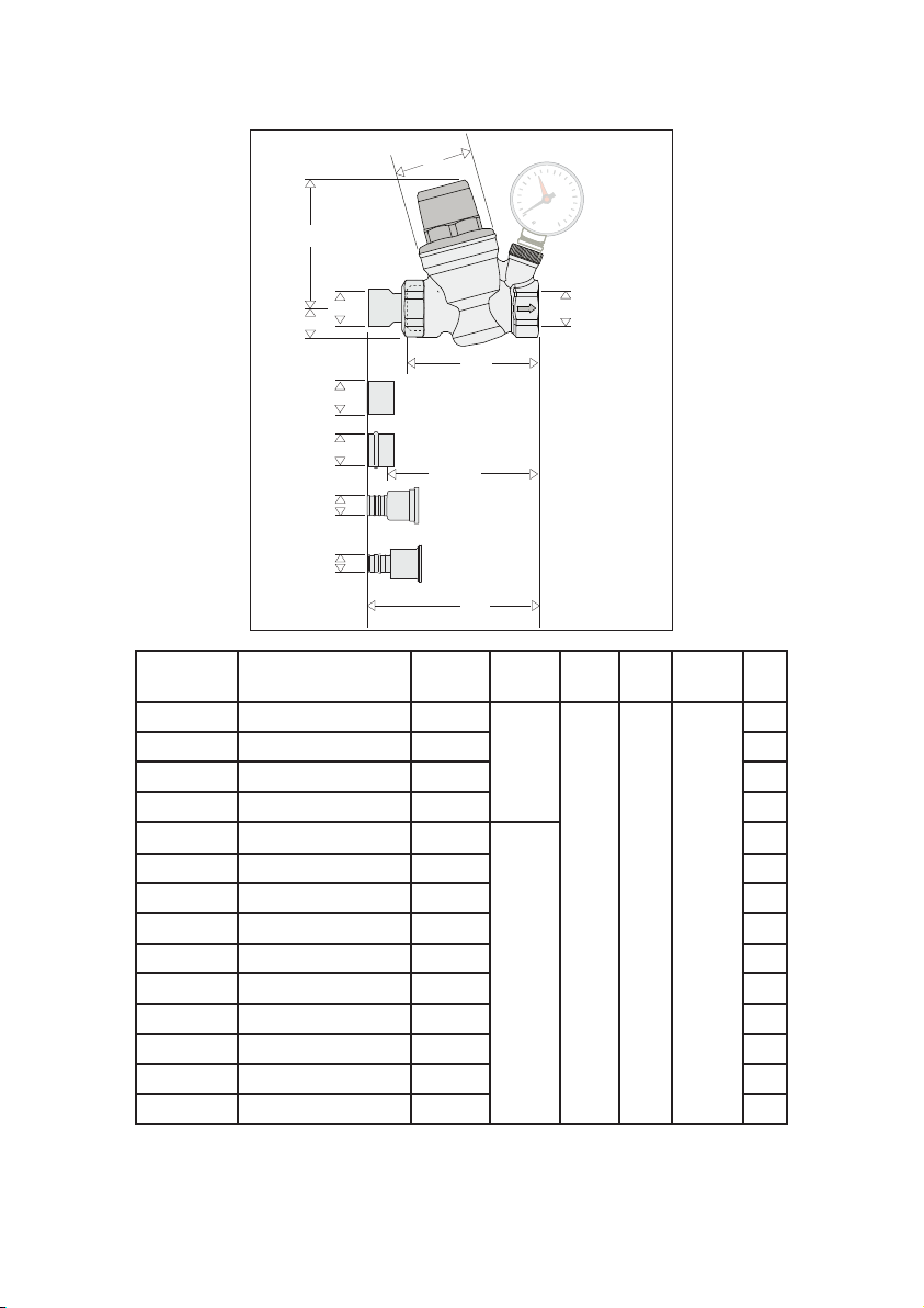
Dimensions
E
DC
NPT female union
A
AA
A
A
CALEFFI
B’
sweat
press
lay length
PEX crimp
PEX expansion
CALEFFI
A
NPT female
internal thread
(all codes)
B
Code A B B' C D E
5
533940HA ½" sweat 3
533941HA ½" sweat* 3
533340HA ½" FNPT 4
533341HA ½" FNPT* 4
533950HA ¾" sweat
/8"
5
/8"
15
/16"
2
1
/16"
1
/16"
4"
Wt
(lb)
1.1
1.2
0.9
1.0
1.3
533951HA ¾" sweat* 4" 1.4
533350HA ¾" FNPT 4 ¼" 1.1
533351HA ¾" FNPT* 4 ¼" 1.2
533650HA ¾" press 4 ¼" 1.5
533651HA ¾" press* 4 ¼" 1.6
9
533750HA ¾" PEX crimp 4
533751HA ¾" PEX crimp* 4
533850HA ¾" PEX expansion 4
533851HA ½" PEX expansion* 4
/16"
9
/16"
15
/16"
15
/16"
¾"
3"
3" 1
7
/8"
1.7
1.8
1.7
1.8
NOTE:
*Configuration includes factory supplied outlet pressure gauge. Models without gauge
have a plugged gauge port.
For press connection, lay length:
size ¾" - 3 ¼"
5
Page 6
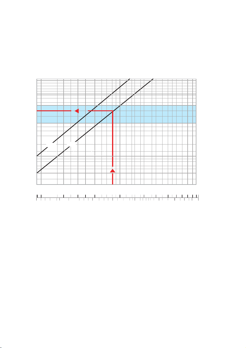
Hydraulic characteristics
Graph 1 (Flow velocity)
V (f/s)
15
10
8
6 1.8
5
4 1.2
3 0.9
2 0.6
1.5
0.3
1/2”
1
1
0.9
0.05
0.1
2
3/4”
3
0.2
4
0.3
5
0.4
0.5
10
20
30
40
506070
80
1
1.5
2
3
2.5
5
4
V (m/s)
5
4
3
0.45
0.3
0.150.5
0.1
90
(gpm)
(/s)
6
Flow rate
6
Page 7
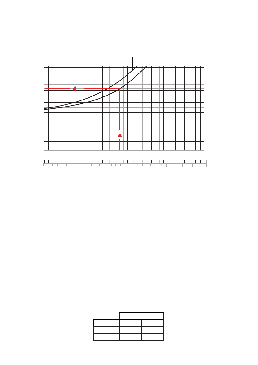
Graph 2 (Pressure drop)
∆
p (psi)
20
15
10
7
5
3
FALL OFF PRESSURE
1/2 in
3/4 in
∆
p (kPa)
150
117
103
90
68
62
48
35
28
20
2
1.5
20
1
0.4
10
0.5
1
0.9
0.05
Reference values: Upstream pressure = 116 psi (800 kPa)
2
0.1
5
3
4
0.2
0.3
1.5
30
40
506070
2
3
2.5
14
10
90
80
(gpm)
(/s)
5
4
6
Flow rate
Downstream presssure = 43 psi (300 kPa)
Sizing procedure
Flow velocity is recommended to be kept within 3 to 6 feet per second when calculating the
correct pressure reducing valve size. This will prevent noise in the pipes and rapid wear of
appliances.
The correct diameter of the pressure reducing valve is taken from graph 1 on the basis of the
design flow rate taking into account an ideal flow velocity of between 3 and 6 f/s (blue band).
Example:
For 8 gpm, select the ¾” size valve (see arrow on graph 1).
The pressure drop is taken from graph 2 also on the basis of where the design flow rate
intersects the curve for the valve size already selected (the downstream pressure falls by an
amount equal to the pressure drop, with respect to the set pressure at no flow condition).
Example:
For 8 gpm the Dp = 10 psi (see arrow on graph 2).
Design Flow Rate
Size ½" ¾"
gpm 3 to 5.6 5.6 to 10
l/s 0.2 to .35 .35 to .63
7
Page 8
Installation
E
B
DN 20
2,27
37,83
C
A
1
L
E
B
2
Ø
G (m
3
/h)
G (l/min)
DN 15
1,27
21,16
DN 20
2,27
37,83
1st stage
PRV
2nd stage
PRV
short short
H
Downstream set pressure (kPa)
2000
1600
1200
800
400
Cavitation
high risk
Normal working
conditions
Out of working
conditions
Upstream pressure (kPa)
100
200
400
600
800
1000
1200
Cavitation diagram
I
Before following the numbered steps listed, the installer must:
a) Be sure this pressure reducing valve is compatible with the other equipment in the system that
it may interact with or come into contact;
b) Assess and acknowledge all hazards related to the use of the this product, including potential
leakage, by installing this unit properly;
c) Install shut-off valve with pressure ports or similar equipment to measure the upstream pressure.
1) Turn all the faucets on before installing the pressure reducing valve, to flush the system and
expel any air remaining in the pipes.
2) Install shut-off valves upstream and downstream to facilitate maintenance operations.
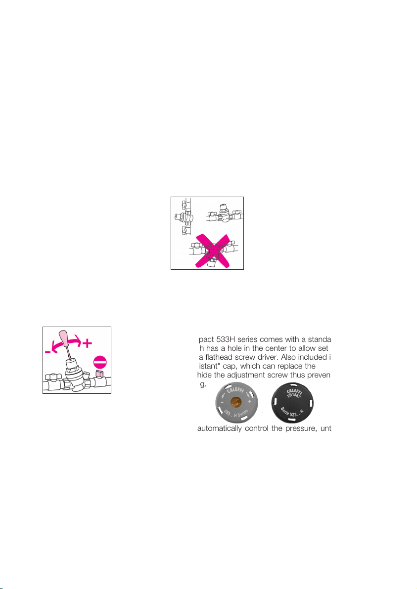
3) The pressure reducing valve may be installed on either vertical or horizontal pipe. However, it
must not be installed upside down.
4) The PresCal 533H series compact pressure reducing valve is factory set to 45 psi (3 bar).
5) Set to another desired pressure by turning the screw on the top of the plastic
cover, clockwise to increase the pressure setting and counter clockwise to
decrease it. Use a pressure gauge to verify the desired pressure setting.
Tamper-resistant cap:
The PresCal Compact 533H series comes with a standard gray
7) After installation, the internal mechanism will automatically control the pressure, until the set
value has been reached.
8) Slowly reopen the downstream shut-off valve.
Installation recommendations
1. Installation below ground
2. Outdoor installation
Installation below the ground is not advisable.
Pressure reducing valves should not be installed outside the building unless properly protected
from freezing and the weather.
snap-on cap which has a hole in the center to allow set point
adjustment using a flathead screw driver. Also included is a
black "tamper-resistant" cap, which can replace the
standard cap, to hide the adjustment screw thus preventing
set point tampering.
3. Water hammer
Water hammer is a common reason for pressure reducing valve failures. Specific devices
should be installed to absorb water hammer for systems with this risk.
8
Page 9
Installation
C
A
E
B
Ø
G (m
3
/h)
G (l/min)
DN 15
1,27
21,16
DN 20
2,27
37,83
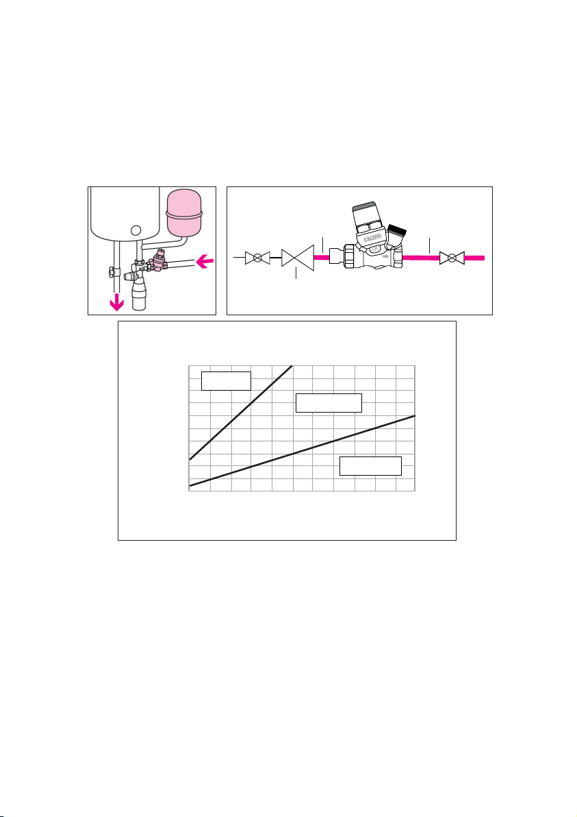
When installing the pressure reducing valve upstream of a hot water tank, installing an expansion
tank, or similar, is recommended to absorb the increase in pressure due to the thermal expansion
of water.
When installing in large buildings, short pipes or expansion valves, and/or similar equipment, is
recommended to limit the increased pressure due to the thermal expansion of water caused by
temperature changes downstream of the pressure reducing valve itself (or downstream of the first
and second stage pressure reducing valves, if two are used).
short short
1st stage
PRV
Cavitation diagram
14
2000
1600
1200
800
400
Upstream pressure (kPa)
100
Downstream set pressure (PSI)
29
Cavitation
high risk
200
58
400
Downstream set pressure (kPa)
87
Normal working
conditions
600
2nd stage
116
Out of working
conditions
800
PRV
145
1000
174
290
232
174
116
58
Upstream pressure (PSI)
1200
To minimize the risk of cavitation within the valve that may result in malfunctioning with erosion
of the valve sealing area, vibrations and noise, it is highly recommended to refer to the working
conditions represented in the above diagram. Due to the numerous factors and variable
conditions experienced such as system pressure, water temperature, air presence, flow rate
and velocity, which may affect the behavior of the pressure reducing valve, it is advisable that
the pressure ratio between the upstream pressure and the downstream set pressure is kept
ideally to a value 2:1 and no greater than a value of 3:1 (For example, upstream 150 psi (10
bar), set pressure 75 psi (5 bar), the pressure ratio = 150/75 = 2:1). In these conditions, the
possible risk of cavitation and malfunctioning is minimized, however this does not exclude the
possible effects of the many other variables within the system under operating conditions. If
the pressure ratio exceeds the indicated limit, the system design pressure or use of 1st stage
pressure reducing valves shall be reviewed (For example, 1st stage reducing pressure from 200
to 100 psi and then 2nd stage from 100 to 60 psi). Piping upstream and downstream of the
pressure reducing valve shall be supported in accordance with the manufacturer’s instructions,
and any local authority requirements, to avoid the creation and transfer of vibration and/or noise
into the installation.
9
Page 10
C
1
L
E
2
Ø
G (m
3
/h)
G (l/min)
DN 15
1,27
21,16
DN 20
2,27
37,83
1st stage
PRV
2nd stage
PRV
short short
H
Downstream set pressure (kPa)
2000
1600
1200
800
400
Cavitation
high risk
Normal working
conditions
Out of working
conditions
Upstream pressure (kPa)
100
200
400
600
800
1000
1200
Cavitation diagram
I
E
B
DN 20
2,27
37,83
1st stage
PRV
2nd stage
PRV
short short
Downstream set pressure (kPa)
2000
1600
1200
800
400
Cavitation
high risk
Normal working
conditions
Out of working
conditions
Upstream pressure (kPa)
100
200
400
600
800
1000
1200
Cavitation diagram
I
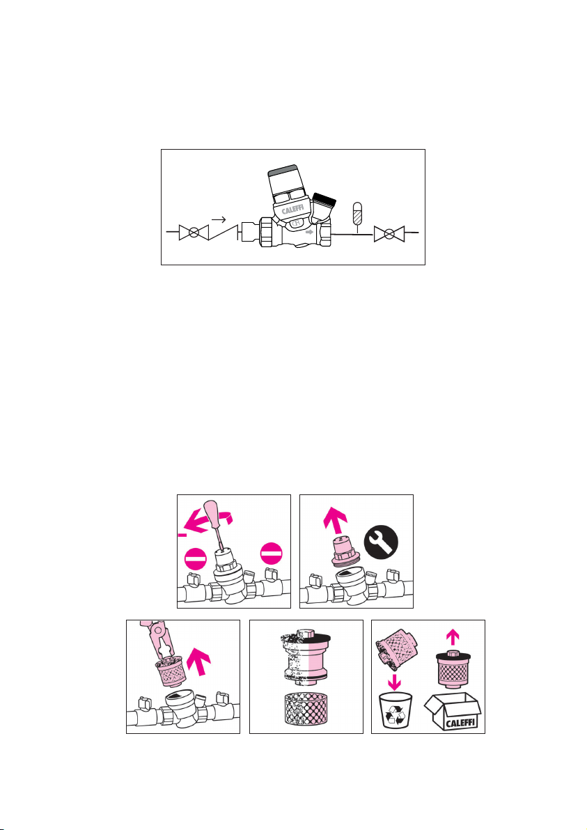
Maintenance
The pressure reducing valve must be checked and serviced to comply with applicable regulations.
Even when installed, commissioned and serviced properly, the pressure reducing valve's internal
components are subject to normal wear and tear, which may result in leaks and other malfunctions.
Check for good working order. Service and clean the cartridge at least every 12 months.
The cartridge, containing the diaphragm, strainer, seat, valve plug and compensating piston, is
pre-assembled as a self-contained unit, comes with a cover and can be removed for inspection
and maintenance. When checking, cleaning or replacing the cartridge:
1) Shut off the inlet and outlet isolation valves. Unscrew the adjustment screw to take off the
tension of the internal spring.
2) Remove the upper cover. This cover is not to be disposed.
3) Using pliers, pull out the cartridge.
4) If needed, the self-contained cartridge can be completely replaced, code 533000H. Install the
new cartridge and previously removed upper cover.
5) Reopen the shut off valves and reset the pressure per instructions on page 8.
3
1
4
2
10
Page 11
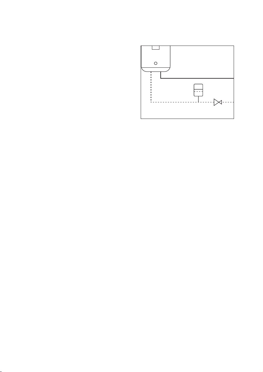
Troubleshooting
System failures are not always caused by the
pressure reducing valve. Most frequently:
1. Increased downstream pressure in the
presence of a water heater
If the downstream pressure increases
beyond the desired setting due to an
inline water heater, install an expansion
tank between the pressure reducing
valve and the water heater to absorb
the increased pressure, caused
by water expansion from heating.
2.The pressure reducing valve does not
maintain downstream setting value
If the pressure reducing valve does
not maintain the downstream setting, it most likely is due to impurities acccumulating
on the valve seat, causing unnecessary flow to pass-through, increasing the downstream
pressure. Proper maintenance and cleaning of the removable cartridge is recommended.
11
Page 12
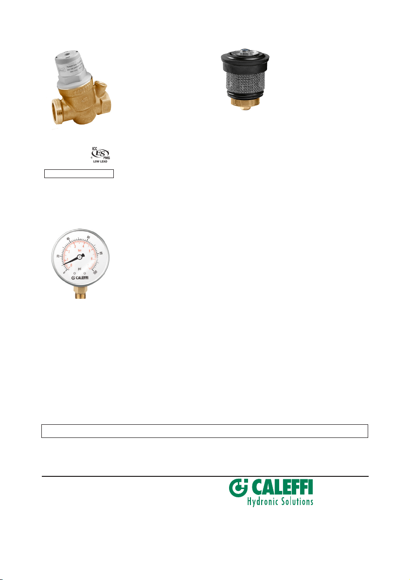
Replacement parts
Replacement valve
body for PresCal
Compact 533H
series pressure
reducing valve. Meets
requirements of
NSF
Certified to:
ASSE 1003/
CSA B356, NSF
61 (180°F/82°C
Commercial Hot), file
PMG-1356. Low
lead, by ICC-ES file
NSF/ANSI/CAN 61
533449HA .....½" body with ¾"
533459HA......¾" body with 1"
PMG-1356.
Pressure gauge fits
533H series pressure
reducing valves.
Pressure range 0 to
100 psi (0 to 7 bar).
NA10273....................................
/ANSI 372.
male union thread
male union thread
1
/8"
NPT male
Replacement cartridge
for PresCal Compact
533H series compact
pressure reducing
valve.
533000H.........Fits 533H size ½" and ¾" valves
LEAVE THIS MANUAL WITH THE USER
Caleffi North America, Inc.
3883 W. Milwaukee Road
Milwaukee, WI 53208
T: 414.238.2360 F: 414.238.2366
12
12-17-20
 Loading...