

Page 1
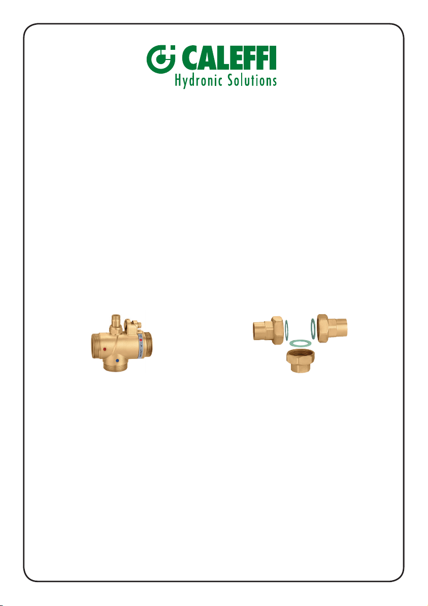
524 series
MISCELATORI TERMOSTATICI
PER IMPIANTI CENTRALIZZATI
THERMOSTATIC MIXING VALVES
FOR CENTRALISED SYSTEMS
MITIGEURS THERMOSTATIQUES
POUR INSTALLATION CENTRALISÉE
524400 DN 15 / 1 1/8”
524500 DN 20 / 1 1/4”
524600 DN 25 / 1 1/2”
524700 DN 32 / 2”
524800 DN 40 / 2 1/4”
524900 DN 50 / 2 3/4”
524004 1/2” for 524400
524005 3/4” for 524500
524006 1” for 524600
524007 1 1/4” for 524700
524008 1 1/2” for 524800
524009 2” for 524900
INSTALLAZIONE, USO E MANUTENZIONE
INSTALLATION, OPERATING AND MAINTENANCE
INSTALLATION, OPÉRATION ET ENTRETIEN
CONSEGNARE QUESTE ISTRUZIONI ALL’UTENTE
S’IL VOUS PLAÎT LAISSER LA PRÉSENTE NOTICE À L’USAGE ET AU SERVICE DE L’UTILISATEUR
PLEASE LEAVE THESE INSTRUCTIONS WITH THE USER
Page 2

INTRODUZIONE
Questa guida all'installazione è stata redatta per i prodotti termostatici
della serie 524. Queste istruzioni descrivono l'installazione, il funzionamento
e la manutenzione dei miscelatori termostatici della serie 524. Leggere
attentamente le istruzioni allegate prima di iniziare l'installazione del
prodotto. Tenere presente quanto indicato di seguito.
SI RACCOMANDA DI FAR ESEGUIRE L'INSTALLAZIONE DEI
PRODOTTI CALEFFI A UN INSTALLATORE AUTORIZZATO.
L'installazione deve essere eseguita rigorosamente in conformità con le
normative relative alla distribuzione idrica e con le leggi locali.
DATI TECNICI
Campo di settaggio della temperatura: 30 ÷ 65 °C
Stabilità della temperatura: ± 2 °C
Pressione max d’esercizio:
(statica) 10 bar
(dinamica) 5 bar
Temperatura max ingresso: 90 °C
Massimo rapporto tra le pressioni in entrata
(C/F o F/C):
Differenziale minimo di temperatura per garantire
la protezione fail-safe tra le mandate di acqua
calda e fredda:
2
2: 1
10 °C
Page 3
ITALIANO
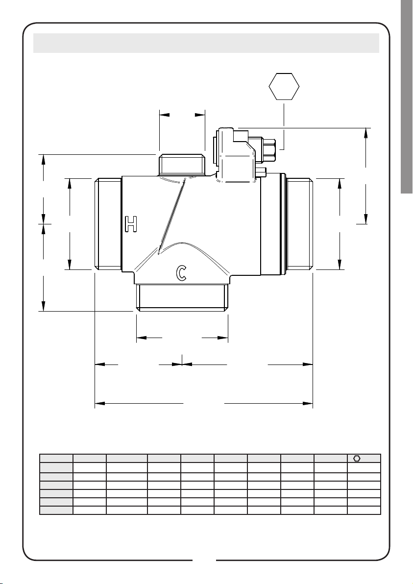
DIMENSIONI
d 2
h 2
d 1
GN DN d1 d2 L1 L2 L3 h1 h2
½ 15
¾ 20
1 25 G 1 ½ G ¾ 43 67 110 36 46,5 9
1 ¼ 32 G 2 G ¾ 52 78 130 41 57,5 10
1 ½ 40 G 2 ¼ G ¾ 58 92 150 50 60,5 12
2 50 G 2 ¾ G ¾ 70 110 180 60 76,5 12
Tutte le dimensioni sono in mm
d 1
L 1 L 2
L 3
G 1 ⅛
G 1 ¼
‒
G ½ 40 60 100 32 44 9
35 55 90
‒
d 1
39,5 7
3
Page 4
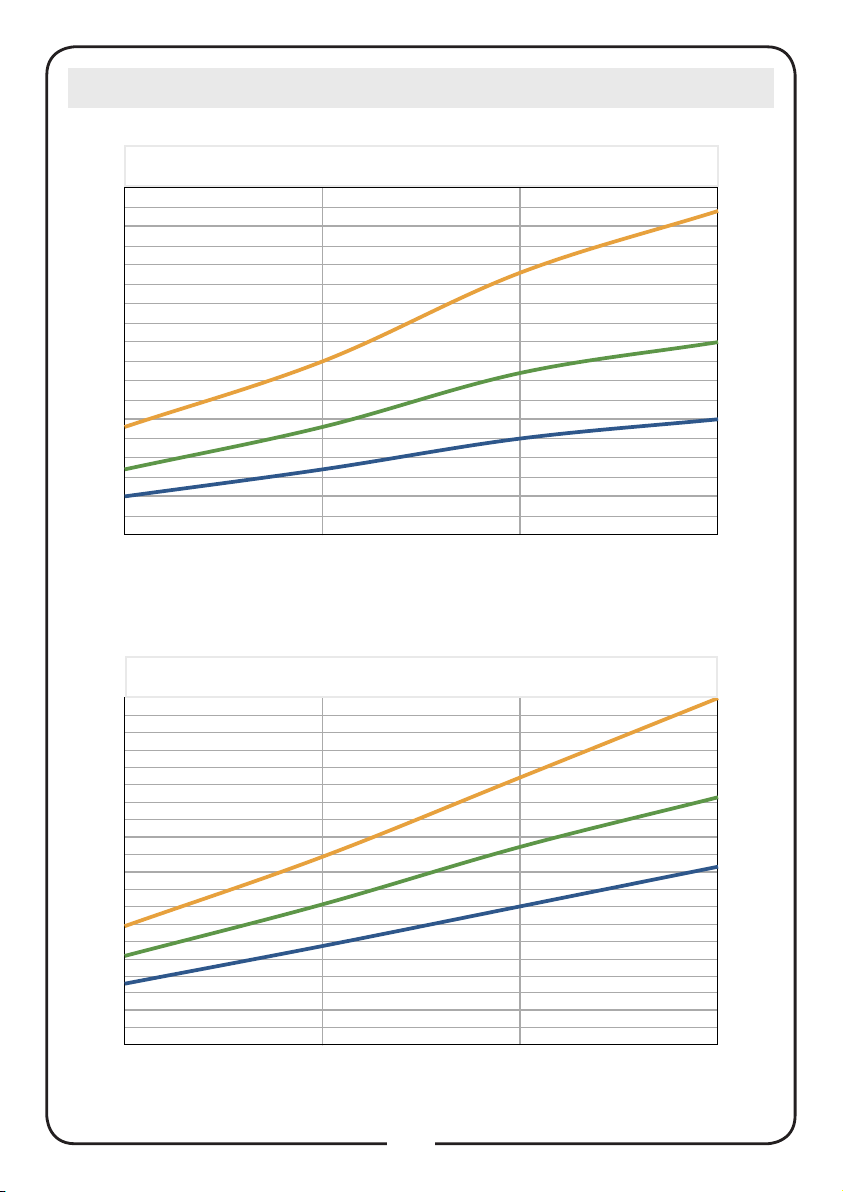
CARATTERISTICHE IDRAULICHE
1/2 "
3/4 "
1 "
101728
172845
254268
305084
1" 1/4
1" 1/2
2"
62
90
120
100
142
190
140
200
270
180
250
350
90
80
70
60
50
40
Q ( l / min )
30
20
10
0
0,2 0,5 1 1,5
ΔP ( bar )
1” 1/4 - 1” 1/2 - 2”
350
315
1/2” - 3/4” - 1”
1 "
3/4 "
1/2 "
2"
280
245
210
175
Q ( l / min )
140
105
70
35
0
0,2 0,5 1 1,5
ΔP ( bar )
4
1" 1/2
1" 1/4
Page 5

ITALIANO
USO
Grazie alle sue particolari caratteristiche, i miscelatori termostatici della
serie 524 possono essere installati negli impianti centralizzati.
ISTRUZIONI PER L'INSTALLAZIONE
Prima di procedere all'installazione del prodotto, verificare che nella
scatola siano presenti tutti i componenti.
Prima di installare un miscelatore serie 524, il sistema deve essere
ispezionato per assicurare che le condizioni di esercizio siano comprese
nei parametri del miscelatore, controllando, ad esempio, la temperatura
di mandata, le pressioni di mandata, e così via.
L'impianto in cui verrà installato il miscelatore serie 524 deve essere
lavato per eliminare tracce di sporco o corpi estranei che potrebbero
essersi accumulati nel corso dell'installazione.
La mancata rimozione di sporco e corpi estranei può influenzare
negativamente le prestazioni e invalidare la garanzia del fabbricante sul
prodotto.
È sempre consigliabile installare filtri di capacità idonea sull'ingresso
dell'acqua dalla mandata principale.
In aree che sono soggette ad acqua molto aggressiva, è necessario
predisporre un dispositivo per il trattamento dell'acqua a monte
dell'ingresso della valvola.
I miscelatori serie 524 devono essere installati seguendo gli schemi
di questo manuale, prendendo in considerazione tutti gli standard
applicabili attuali e i codici di procedura.
I miscelatori termostatici serie 524 possono essere installati in qualsiasi
posizione, sia verticale che orizzontale.
Sul corpo della valvola sono evidenziati:
ingresso acqua calda, H e colore rosso
ingresso acqua fredda, C e colore blu
È fondamentale che l'accesso alla valvola sia totalmente sgombro per
consentire di effettuare gli eventuali interventi di manutenzione richiesti
per la valvola o i raccordi. La tubazione da/alla valvola non deve essere
usata come sostegno del peso della valvola stessa.
5
Page 6
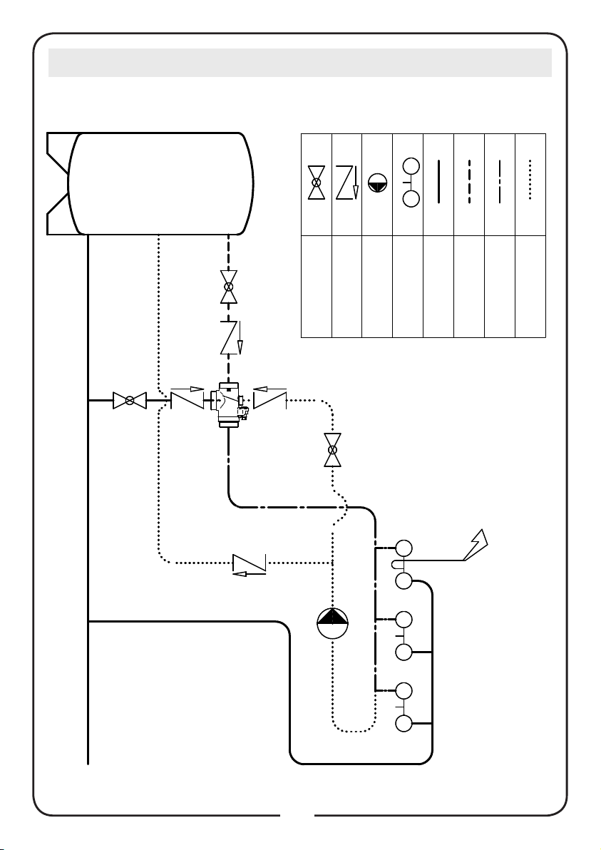
DATI DI INSTALLAZIONE TIPICA
CALDAIA
VALVOLA DI NON
RITORNO
VALVOLA A SFERA
ACQUA DI
RICIRCOLO
ACQUA
MISCELATA
ACQUA CALDA
ACQUA FREDDA
UTENZE
POMPA
6
Page 7
ITALIANO
MESSA IN SERVIZIO
Dopo l'installazione, la valvola deve essere testata e messa in servizio
secondo le istruzioni fornite di seguito, tenendo presenti gli standard
attuali applicabili e i codici di procedura.
1. Assicurarsi che l'impianto sia pulito e privo di sporco o corpi estranei
prima di mettere in servizio il miscelatore termostatico.
2. Si raccomanda di settare la temperatura utilizzando un termometro
digitale calibrato idoneo. La valvola deve essere messa in servizio
misurando la temperatura dell’acqua miscelata in uscita al punto di
utilizzo.
3. La temperatura di scarico massima dalla valvola deve essere
settata tenendo conto delle fluttuazioni dovute all'uso simultaneo.
È fondamentale stabilizzare queste condizioni prima della messa in
servizio.
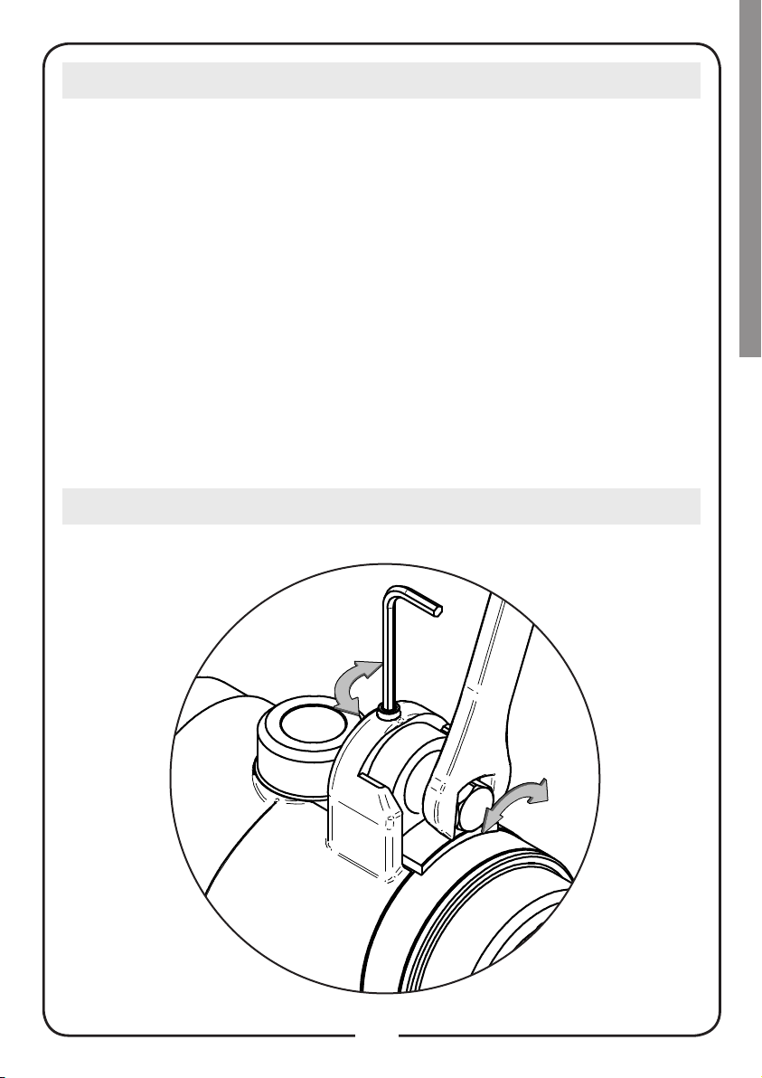
4. Regolare la temperatura utilizzando la vite di regolazione sulla
valvola.
BLOCCAGGIO PREIMPOSTATO
7
Page 8

MANUTENZIONE
Durante l'uso è necessario eseguire regolarmente dei test per controllare
il funzionamento del miscelatore, in quanto un deterioramento potrebbe
indicare che la valvola e o l'impianto necessitano di manutenzione.
Se nel corso dei test la temperatura dell'acqua miscelata risulta
sensibilmente diversa rispetto al test precedente, è necessario controllare
le informazioni fornite nelle sezione sull'installazione e la messa in servizio
ed eseguire la manutenzione.
Verificare regolarmente i seguenti aspetti per assicurare che siano
mantenuti i livelli ottimali di rendimento della valvola. Ogni 12 mesi
almeno, più spesso se necessario.
1. Controllare e pulire i filtri dell'impianto.
2. Verificare che le valvole di non ritorno funzionino correttamente,
senza problemi causati dalle impurità.
3. Il calcare può essere eliminato dai componenti interni immergendoli
in un liquido anticalcare idoneo.
4. Una volta controllati i componenti di cui è possibile eseguire la
manutenzione, occorre eseguire di nuovo la messa in servizio.
8
Page 9

ENGLISH
INTRODUCTION
This installation guide has been produced for the 524 series thermostatic
products. These instructions cover the installation, operation and
maintenance of the 524 series thermostatic mixing valves. Please read
the enclosed instructions before commencing the installation of this
product, please note;
WE RECOMMEND THAT THE INSTALLATION OF ANY CALEFFI
PRODUCT IS CARRIED OUT BY AN APPROVED INSTALLER
The installation must be carried out strictly in accordance with the Water
Supply Regulations and any local authority regulation.
TECHNICAL DATA
Temperature setting range : 30 ÷ 65 ° C
Temperature stability : ± 2 ° C
Max working pressure :
( static ) 10 bar
( dynamic ) 5 bar
Max inlet temperature : 90 ° C
Maximum inlet pressure ratio ( H/C or C/H ) : 2 : 1
Min. temperature differential to ensure fail safe
between hot and cold supplies : 10 ° C
9
Page 10

DIMENSIONS
d 2
h 2
d 1
d 1
d 1
L 1 L 2
L 3
GN DN d1 d2 L1 L2 L3 h1 h2
½ 15
¾ 20 G 1 ¼ G ½ 40 60 100 32 44 9
1 25 G 1 ½ G ¾ 43 67 110 36 46,5 9
1 ¼ 32 G 2 G ¾ 52 78 130 41 57,5 10
1 ½ 40 G 2 ¼ G ¾ 58 92 150 50 60,5 12
2 50 G 2 ¾ G ¾ 70 110 180 60 76,5 12
All dimensions in mm
G 1 ⅛
‒
35 55 90
‒
39,5 7
10
Page 11

ENGLISH
HYDRAULIC CHARACTERISTICS
1/2 "
3/4 "
1 "
101728
172845
254268
305084
1" 1/4
1" 1/2
2"
62
90
120
100
142
190
140
200
270
180
250
350
90
80
70
60
50
40
Q ( l / min )
30
20
10
0
0,2 0,5 1 1,5
ΔP ( bar )
1” 1/4 - 1” 1/2 - 2”
350
315
1/2” - 3/4” - 1”
1 "
3/4 "
1/2 "
2"
280
245
210
175
Q ( l / min )
140
105
70
35
0
0,2 0,5 1 1,5
1" 1/2
1" 1/4
ΔP ( bar )
11
Page 12

USE
Thanks to their special features, the 524 series thermostatic mixing valves,
can be installed on centralized systems.
INSTALLATION INSTRUCTIONS
Please check that all the components are in the box prior to the
installation of this product.
Before installing a 524 series mixer, the system must be inspected to
ensure that it’s operating conditions are within the range of the mixer,
checking, for example, the supply temperature, supply pressures, etc.
System where the 524 series mixer is to be fitted must be flushed to remove
any dirt or debris which may have accumulated during installation.
Failure to remove dirt or debris may affect performance and the
manufacturer’s product guarantee.
The installation of filters of appropriate capacity at the inlet of the water
from the main supply is always advisable.
In areas which are subject to highly aggressive water, arrangements
must be made to treat the water before it enters the valve.
524 series mixers must be installed in accordance with the diagrams in this
manual, taking into account all current applicable standards and code
of practice.
Caleffi 524 series mixers can be installed in any position, either vertical or
horizontal.
The following are shown on the mixer body:
hot water inlet, H and colour red
cold water inlet, C and colour blue
It is essential that access to the valve is totally unobstructed for any
maintenance which may be required to the valve or connections. The
pipework from/to the valve must not be used to support the weigh of the
valve itself.
12
Page 13

ENGLISH
TYPICAL INSTALLATION DETAILS
BOILER
NO RETURN
VALVE
BALL VALVE
PUMP
USERS
COLD WATER
HOT WATER
MIXING WATER
WATER
RECYCLING
13
Page 14

COMMISSIONING
After installation, the valve must be tested and commissioned in
accordance with the instructions given below, taking into account
current applicable standards and code of practice.
1. Ensure that the system is clean and free from any dirt or debris before
commissioning the thermostatic mixer.
2. It is recommended that the temperature is set using a suitable
calibrated digital thermometer. The valve must be commissioned by
measuring the temperature of the mixed water emerging at the point
of use.
3. The maximum discharge temperature from the valve must be set
taking account of the fluctuations due to simultaneous use. It is
essential for these conditions to be stabilised before commissioning.
4. Adjust the temperature using the adjusting screw on the valve.
PRESET LOCKING
14
Page 15

ENGLISH
MAINTENANCE
In service tests should be carried out regularly to monitor the mixer
performance, as deterioration of performance could indicate that the
valve and/or the system require maintenance. If, during these tests, the
temperature of the mixed water has changed significantly in comparison
with the previous test, the details given in installation and commissioning
sections should be checked and maintenance carried out.
The following aspects should be checked regularly to ensure that the
optimum performance levels of the valve are maintained. Every 12 months
at the last, or more often if necessary.
1. Check and clean the system filters.
2. Check that non-return valves are operating correctly, without
problems caused by impurities.
3. Limescale can be removed from internal components by immersion
in a suitable de-scaling fluid.
4. When the components which can be maintained have been
checked, commissioning should be carried out again.
15
Page 16

INTRODUCTION
Ce mode d’emploi a été conçu pour les mitigeurs thermostatiques de
série 524. Il donne les instrucions d’installation, de mise en oeuvre et de
maintenance des mitigeurs thermostatiques série 524. Lire attentivement
ces instructions avant de commencer l’installation du produit.
LE MITIGEUR THERMOSTATIQUE DOIT ÊTRE MONTÉ PAR UN
MONTEUR QUALIFIÉ
Le mitigeur thermostatique doit être monté conformément aux règlements
nationaux et (ou) locaux.
CARACTÉRISTIQUES TECHNIQUES
Plage de réglage : 30 ÷ 65 ° C
Précision : ± 2 ° C
Pression maxi d’exercice :
( statique ) 10 bar
( dynamique ) 5 bar
Température maxi d’entrée : 90 ° C
Rapport maximum entre les pressions en entrée
(C/F ou F/C) :
Différence de température minimum entre l’entrée
de l’eau chaude et la sortie de l’eau mitigée :
16
2 : 1
10 ° C
Page 17

FRANÇAIS
DIMENSIONS
d 2
h 2
d 1
GN DN d1 d2 L1 L2 L3 h1 h2
½ 15
¾ 20 G 1 ¼ G ½ 40 60 100 32 44 9
1 25 G 1 ½ G ¾ 43 67 110 36 46,5 9
1 ¼ 32 G 2 G ¾ 52 78 130 41 57,5 10
1 ½ 40 G 2 ¼ G ¾ 58 92 150 50 60,5 12
2 50 G 2 ¾ G ¾ 70 110 180 60 76,5 12
Toutes les dimensions en mm
d 1
L 1 L 2
L 3
G 1 ⅛
‒
35 55 90
‒
d 1
39,5 7
17
Page 18

CARACTÉRISTIQUES HYDRAULIQUES
1/2 "
3/4 "
1 "
101728
172845
254268
305084
1" 1/4
1" 1/2
2"
62
90
120
100
142
190
140
200
270
180
250
350
90
80
70
60
50
40
Q ( l / min )
30
20
10
0
0,2 0,5 1 1,5
ΔP ( bar )
1” 1/4 - 1” 1/2 - 2”
350
315
1/2” - 3/4” - 1”
1 "
3/4 "
1/2 "
2"
280
245
210
175
Q ( l / min )
140
105
70
35
0
0,2 0,5 1 1,5
ΔP ( bar )
18
1" 1/2
1" 1/4
Page 19

FRANÇAIS
UTILISATION
Grace à leurs caractéristiques techniques, les mitigeurs thermostatiques
série 524 peuvent etre utilisés dans des installations à production
centralisée.
INSTRUCTIONS D’INSTALLATION
Vérifier qu’il ne manque aucun éléments dans l’emballage.
Avant la pose du mitigeur thermostatique série 524, l’installation doit être
contrôlée afin de s’assurer que les conditions opérationnelles entrent
bien dans le champ de fonctionnement du mitigeur, par exemple vérifier
les températures d’alimentation, les pressions d’alimentation, etc.
L’installation doit être purgée et nettoyée de toutes saletés qui auraient
pu s’accumuler pendant la pose. La présence de saletés peut influencer
la prestation de l’appareil et ne plus garantir son bon fonctionnement.
Il est conseillé de monter un filtre de capacité suffisante à l’arrivée du
réseau d’eau.
Dans les zones sujettes à des qualités d’eaux très agressives, il convient
de prévoir un dispositif de traitement d’eau avant le mitigeur.
Le mitigeur thermostatique série 524 peut être installé dans n’importe
quelles positions, verticales ou horizontales.
Sur le corps du mitigeur sont mis en évidence:
- L’entrée eau chaude avec la couleur rouge.
- L’entrée eau froide avec la couleur bleue.
Il est impératif de laisser libre l’accès au mitigeur et à ses raccordements
pour la manutention éventuelle. La tubulure utilisée doit pouvoir supporter
le poids du mitigeur.
19
Page 20

SCHÉMAS D’INSTALLATION
CIRCUIT
BOUCLAGE
EAU CHAUDE
CLAPET
ANTI-RETOUR
BOILER
CIRCULATEUR
POINTS DE
PUISAGE
EAU FROIDE
20
Page 21

FRANÇAIS
MISE EN SERVICE
Après la pose, le mitigeur doit être testé et mise en service en suivant les
instructions suivantes, en tenant compte des normes en vigueur.
1. S’assurer que l’installation soit propre et nettoyée de toutes impuretés
avant la mise en service du mitigeur thermostatique.
2. Il est recommandé de régler la température en utilisant un
thermomètre digital calibré. Le mitigeur doit être mis en service en
mesurant la température de l’eau mitigée à un point de puisage.
3. La température maximum en sortie d’eau mitigée doit être réglée en
tenant compte des fluctuations des puisages simultanés.
4. Il est indispensable que ces conditions soient établies avant la mise
en service.
5. Régler la température à l’aide de la manette de réglage du mitigeur.
BLOCAGE DU RÉGLAGE
21
Page 22

FRANÇAIS
ENTRETIEN
Les essais en service servent à vérifier régulièrement les prestations du
mitigeur, étant donné qu’une détérioration des prestations peuvent
indiquées la nécessité d’un entretien du mitigeur et/ou de l’installation.
Si, durant ces essais, la température de l’eau mitigée a changé de
manière significative par rapport aux essais précédents, il faut vérifier
les paramètres reportés aux chapitres installation et mise en service et
effectuer l’entretien.
Pour un bon fonctionnement du mitigeur, il est nécessaire de contrôler
périodiquement les points suivants au moins une fois par an ou plus en
cas de nécessité:
1. Contrôler et nettoyer les filtres présents dans l’installation.
2. Contrôler que les éventuels clapets anti-retour montés à l’entrée du
mitigeur fonctionnent parfaitement sans fuite dû à des impuretés.
3. Les composants internes peuvent être détartrés par immersion d’un
liquide détartrant.
4. Une fois l’entretien effectué, refaire la mise en service en suivant les
instructions du chapitre correspondant.
22
Page 23

FRANÇAIS
23
Page 24

www.caleffi.com
24
 Loading...