

Page 1
www.caleffi.com
38476.08
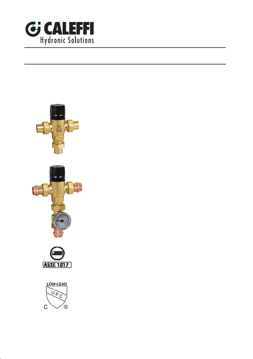
MixCal™ adjustable three-way thermostatic mixing valve
© Copyright 2015 Caleffi
Installation, commissioning and service instructions
Function
The Caleffi MixCal™ three-way thermostatic mixing valve is used in systems
producing domestic hot water or in hydronic and radiant heating systems.
It maintains the desired output temperature of the mixed water supplied to
the user at a constant set value compensating for both temperature and
pressure fl uctuations of incoming hot and cold water.
Product range
521A Series Three-way thermostatic mixing valve:
“C” models include inlet check valves “419, 519, 619” models include
outlet gauge adapter. Union thread NPT Male, sizes ½”, ¾”, 1”; Union
sweat, size ½”, ¾”, 1”. Press connection ¾”.
Technical Characteristics
Materials: -Body: low-lead brass (<0.25% Lead content)
-Shutter, seats and sliding guides: PPO
-Springs: Stainless steel
-Seals: EPDM
Suitable fl uids: water, 30% max glycol solution
Setting range (outlet temperature): 85–150°F (30–65°C)
Tolerance: ±3°F (±2°C)
Max working pressure (static): 200 psi (14 bar)
Max working pressure (dynamic): 75 psi (5 bar)
Hot water inlet temperature range: 120–185°F (49–85°C)
521 Series
Cold water inlet temperature range: 39–80°F (3.9–26.6°C)
Maximum inlet pressure ratio (H/C or C/H) for optimum performance: 2:1
Minimum temperature difference between hot water inlet and mixed
water outlet for optimum performance: 27ºF (15ºC)
Minimum fl ow rate to ensure optimal performance: 1.3 GPM (5 L/min)
Lay length (¾” press connection), hot to cold inlet: 3
Maximum fl ow rate: 15 GPM(57 L/min)
Certifi ed to: cUPC listed to ASSE 1017/CSA B125.3
Reduction of Lead in Drinking Water Act compliant: 0.25% Max. weighted
average lead content
Reduction of Lead in Drinking Water Act Certifi ed by IAPMO R&T. Meets
requirements of ANSI/ NSF 372-2011.
7
/8”
Page 2
SAFETY INSTRUCTION
This safety alert symbol will be used in this manual to draw attention to safety related
instructions. When used, the safety symbol means ATTENTION! BECOME ALERT!
YOUR SAFETY IS INVOLVED! FAILURE TO FOLLOW THESE INSTRUCTIONS MAY
RESULT IN A SAFETY HAZARD.
CAUTION: All work must be preformed by qualied personnel trained
in the proper application, installation, and maintenance of systems in
accordance with all applicable codes and ordinances.
CAUTION: If the thermostatic mixing valve is not installed, commissioned
and maintained properly, according to the instructions contained in this
manual, it may not operate correctly and may endanger the user.
CAUTION: Make sure that all the connecting pipework is water tight.
CAUTION: When making the water connections, make sure that the
pipwork connecting the MixCal thermostatic mixing valve is not mechanically
overstressed. Over time this could cause breakages, with consequent water
losses which, in turn, could cause harm to property and/or people.
CAUTION: Water temperatures higher than 100ºF (38ºC) can be
dangerous. During the installation, commissioning and maintenance of the
MixCal thermostatic mixing valve, take the necessary precautions to ensure
that such temperatures do not endanger people.
CAUTION: In the case of highly aggresive water, arrangements must
be made to treat the water before it enters the thermostatic mixing valve,
in accordance with current legislation. Otherwise the thermostatic mixing
valve may be damaged and will not operate correctly.
CAUTION: If installed in an ASSE 1017 application, check valves shall
be used.
Leave this manual for the user.
Page 3
COLD
HOT
MIX
Operating principle
COLD
HOT
MIX
∆
0.001
0.002
0.003
0.005
0.004
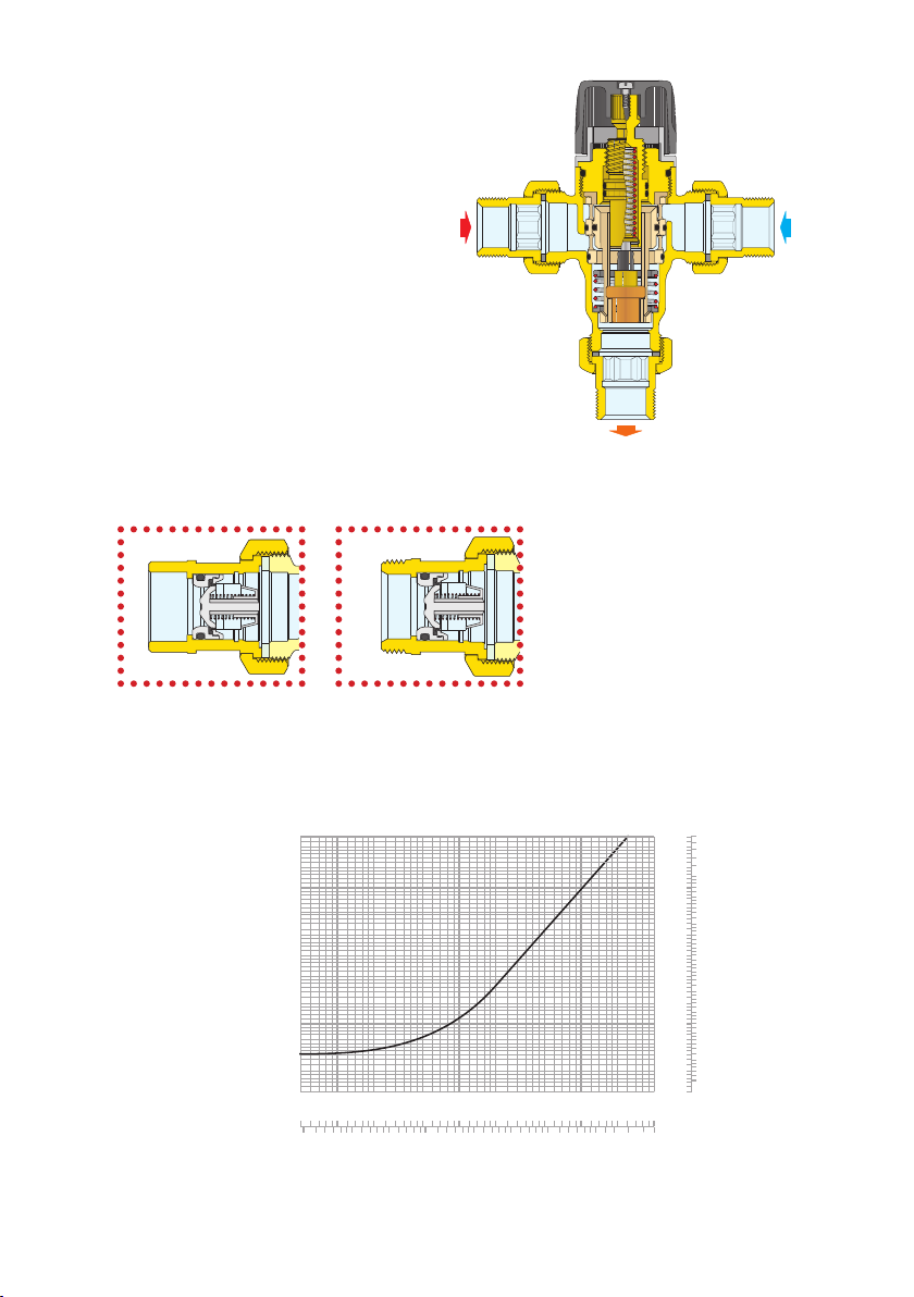
The controlling element of the three-way
thermostatic mixing valve is a thermostatic
sensor fully immersed in the mixed water
outlet tube which, as it expands or contracts,
continuously establishes the correct proportion
of hot and cold water entering the valve. The
regulation of these flows is by means of a
HOT
piston sliding in a cylinder between the hot
and cold water passages. Even when there
are pressure drops due to the drawing off of
hot or cold water for other uses, or variations
in the incoming temperature, the thermostatic
mixing valve automatically regulates the water
flow to obtain the required temperature.
Inlet port check valve detail for 521 “AC” models
COLD
MIX
Flow curve
p (ft of head)
161
115
46
23
11.5
9.2
6.9
4.6
2.3
1.15
0.92
0.69
0.46
0.23
0.115
0.092
0.069
0.046
0.023
Cv = 3.0
1
.
.05
0
0.02
.2
0
0
0.1
0.05
Kv = 2.6
1
0.5
0.2
0.5
Flow should never exceed standards for pipe size and materials.
2
10
(psi) (bar)
5.0
70
50
2.0
20
1.0
10
0.5
0.4
5
0.3
4
3
0.2
2
0.1
1
0.05
0.04
0.5
0.03
0.4
0.3
0.02
0.2
0.01
0.1
0.05
0.04
0.03
0.02
0.01
)
0
gpm
5
10
20
50
2
70
50
100
140
190
G (l/min) (
Page 4
Use
Caleffi MixCal series 521 thermostatic mixing valves are designed to be installed at the hot
water heater. The Caleffi Mix Cal series 521 valve cannot be used for tempering water temperature at
fixtures as a point-of-use valve. They are not designed to provide scald protection or anti-chill service.
They should not be used where ASSE 1070 devices are required. Wherever a scald protection
feature is required, Caleffi series 5213 high performance mixing valve needs to be installed. For safety
reasons, it is advisable to limit the maximum mixed water temperature to 120ºF.
Instantaneous production of hot water
Caleffi MixCal series 521 thermostatic mixing valves should not be used with boilers without storage
that give you instaneous production of domestic hot water. Their addition would compromise the
correct operation of the boiler itself.
Installation
NOTE TO INSTALLER: The Caleffi MixCal series 521 thermostatic mixing valve should be installed
by qualified personnel, in accordance with local codes and ordinances. It is the responsibility of
the installer to properly select, install and adjust this thermostatic mixing valve as specified in these
instructions.
Before installing a Caleffi MixCal series 521 thermostatic mixing valve, the system must be
inspected to ensure that it’s operating conditions are within the range of the thermostatic mixing
valve checking, for example, the supply temperature, supply pressure, etc.
Systems where the Caleffi MixCal series 521 thermostatic mixing valve is to be installed
must be drained and cleaned out to remove any dirt or debris which may have accumulated during
installation. Failure to remove dirt or debris may affect performance and the manufacturer’s product
guarantee. The installation of filters of appropriate capacity at the inlet of the water from the mains
supply is always advisable. In area which are subject to highly aggressive water, arrangements must
be made to treat the water before it enters the valve.
Caleffi MixCal series 521 thermostatic mixing valves must be installed in accordance with the
diagrams in this manual, taking into account all current applicable standards.
Caleffi Mix Cal series 521 thermostatic mixing valves can be installed in any position, either vertical
or horizontal.
The following are shown on the mixer body:
– Hot water inlet, color red and marker “HOT”.
– Cold water inlet, color blue and marker “COLD”.
– Mixed water outlet, marker “MIX”.
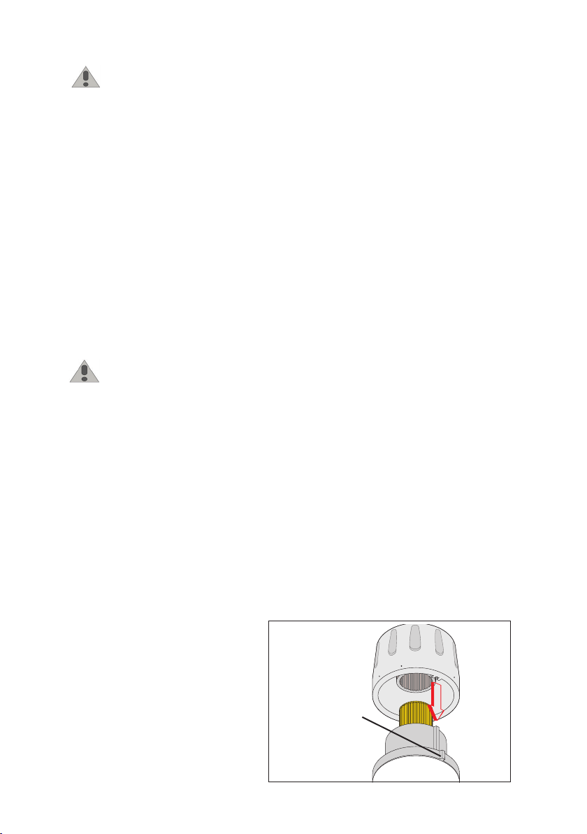
Locking the setting
Position the handle to the number required
with respect to the index point. Unscrew the
head screw, pull off the handle and reposition
it so that the handle fits into the internal slot
of the knob. Tighten the head screw.
3
Index
1
M
I
2
N
M
A
X
7
Point
Page 5
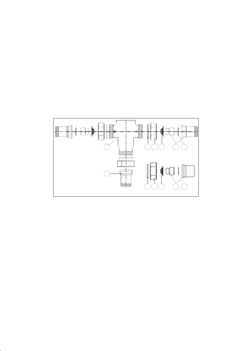
Check valves
In order to prevent undersirable backsiphonage, separate check valves should be installed in systems
with code “521 A” model thermostatic mixing valves (these models do not contain integral check valves
in the hot and cold inlet ports). As a convenience for easier installations, the Caleffi code “521 AC”
model series thermostatic mixing valves include integral check valves in the hot and cold inlet ports.
NOTE TO INSTALLER: DO NOT TEST FIT OR INSTALL CHECK VALVES BEFORE SOLDERING. IF
INSTALLED, REMOVAL WILL REQUIRE DAMAGING THE CHECK VALVE AND IT WILL NO LONGER
BE USABLE.
The diagram below shows the order in which everything goes together. Note that the check valves
are installed on the hot and cold inlets, the mixed outlet does not require a check valve. Note that the
O-ring is installed on to the groove of the check valve.
After soldering the tailpieces into place, slide in the check valve into the tailpiece with o-ring going in
first. It will click into place and then the screen will fit into the groove of the tailpiece with the domed
end facing the mixing valve. Once the check valve and screen is installed, use the sealing washer
between the tailpiece and mixing valve body to create a seal and tighten down the union nut.
1
VALV E BODY
2
UNION WASHER, Quantity 3 per valve
3
UNION NUT, Quantity 3 per valve
4
INLET PORT MALE TAILPIECE
WITH INTEGRAL CHECK VALV E
Quantity 2 per valve
5
CHECK VALVE O-RING
INLET PORT CONIC FILTER,
6
Quantity 2 per valve
OUTLET PORT TAILPIECE,
7
Quantity 1 per valve
2
7
2 3 6
(SWEAT TAILPIECE)
41 3
6
5
4
5
Commissioning
The special purpose of the thermostatic mixing valve must be commissioned in accordance with
current standards by qualified personnel using temperature measuring equipment. Caleffi codes
521419A, 521519A, and 521619A with integral outlet port temperature gauges provide a time-saving
temperature setting process to get close to the desired temperture. Use of a digital thermometer is
recommended for determining the final setting of the mixed water temperature.
NOTE: Gauge adapters with 2” diameter, 20-210ºF scale, code NA10328 (1/2” sweat), NA10056
(3/4” sweat) or NA10058 (1” sweat) can be separately purchased and field installed to the Caleffi
MixCal series 521 models sold without the integral gauge adapters.
After installation, the valve must be tested and commisioned in accordance with instructions given
below, taking into account current applicable standards.
1) Ensure that the system is clean and free from dirt or debris before commissioning the thermostatic
mixer.
2) It is recommended that the temperature is set using a suitable calibrated digital thermometer.
The valve must be commissioned by measuring the temperature of the mixed water emerging at the
point of use.
3) The maximum outlet temperature from the valve must be set taking account of the fluctuations
due to simultaneous use. It is essential for these conditions to be stabilised before commissioning.
4) Adjust the temperature using the adjusting knob on the valve. For safety reasons. it is advisable to
limit the maximum mixed water temperature to 120ºF in domestic hot water systems.
Page 6
MIX
3
2
4
SUPPLY
HOTCOLD
MIX
BOILER
SUPPLY
MIX
3
2
4
MIX
3
2
4
Safety relief valve
Check valve
Isolation valve
Expansion vessel
Filter
Pump
*
*
*
*
*
*
WATER
HEATER
WATER
HEATER
C
A
LE
F
F
I
CA
L
E
F
F
I
CALEFFI
CALEFFI
10
0
8
6
4
2
10
0
8
6
4
2
CALEFFI
CALEFFI
10
0
8
6
4
2
10
0
8
6
4
2
10
0
8
6
4
2
10
0
8
6
4
2
MIX
3
2
4
SUPPLY
HOTCOLD
MIX
MIX
3
2
4
*
*
*
*
WATER
HEATER
C
A
LE
F
F
I
CA
L
E
F
F
I
CALEFFI
CALEFFI
10
0
8
6
4
2
10
0
8
6
4
2
CALEFFI
CALEFFI
10
0
8
6
4
2
10
0
8
6
4
2
10
0
8
6
4
2
10
0
8
6
4
2
MIX
3
2
4
HOTCOLD
MIX
BOILER
Safety relief valve
Check valve
Isolation valve
Expansion vessel
Filter
Pump
*
*
C
A
LE
F
F
I
CA
L
E
F
F
I
CALEFFI
CALEFFI
10
0
8
6
4
2
10
0
8
6
4
2
CALEFFI
CALEFFI
10
0
8
6
4
2
10
0
8
6
4
2
10
0
8
6
4
2
10
0
8
6
4
2
Temperature adjustment
The temperature is set to the required value by means of the knob with a graduated scale, on the
top of the valve.
Pos. Min. 1 2 3 4 5 6 7 Max
T (ºF) 81 90 100 111 120 127 138 145 152
with: T = 155ºF (68ºC) . T = 55ºF (13ºC) . P = 43 psi (3 bar)
Hot Cold
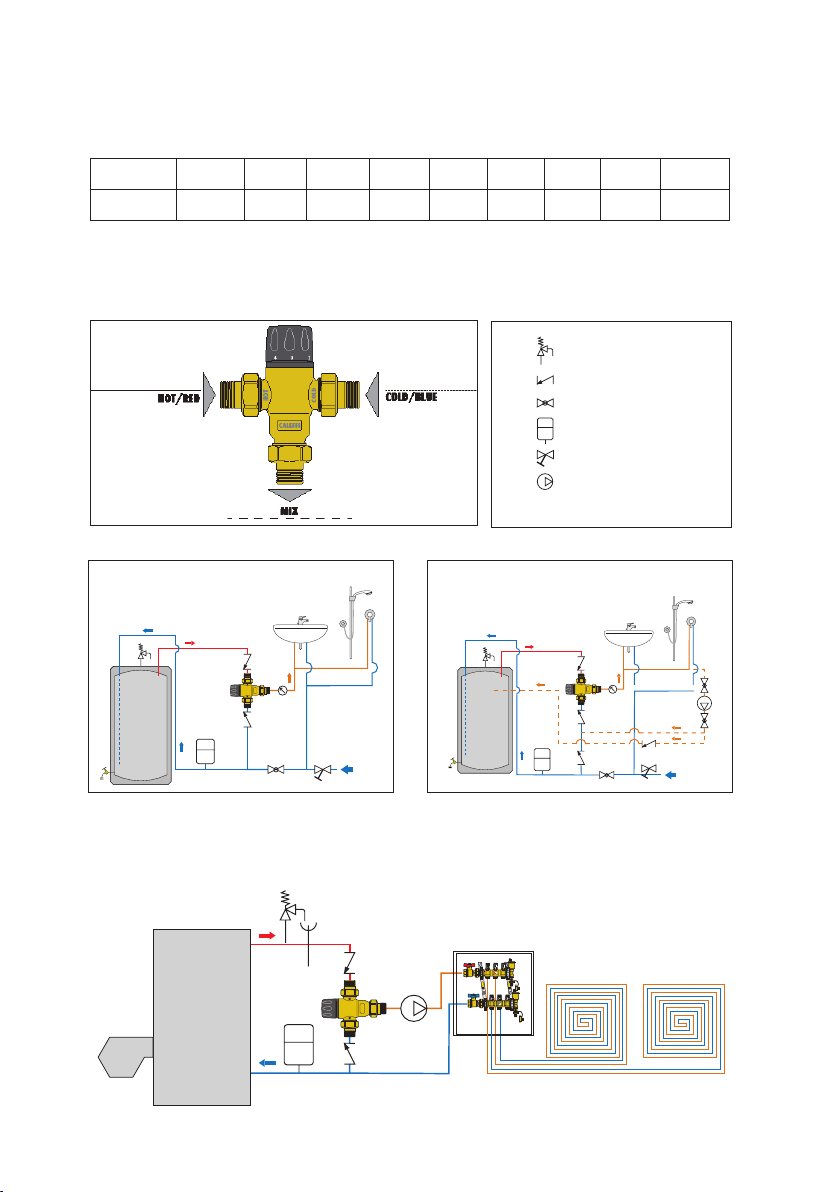
Application Diagrams
Domestic hot water system
without recirculation
*MixCal series 521 thermostatic mixing valves with inlet check valves, “AC” models, can be used
instead of separately installed check valves.
*
HOTCOLD
2
3
MIX
BOILER
4
*
Domestic hot water system
with recirculation
10
10
10
8
8
8
6
6
6
4
4
4
2
2
2
0
0
0
CALEFFI
I
F
F
LE
A
C
MIX
10
10
10
8
8
8
6
6
6
4
4
4
2
2
2
0
0
0
CALEFFI
I
F
F
E
L
CA
CALEFFI
CALEFFI
Page 7

Radiant panels heating system
Replacement fittings
1/2 inch 3/4 inch 1 inch
Item
Description
Union
washer
Union
n ut 1"
Male
tailpieces
Inlet male
tailpiece
with check
valve –
“AC” models only
Outlet
tailpi ece –
“AC” models only
Outlet
adapter
with temperatu re
gauge
*Tailpiece fitting with integral union nut. 1" NPT and Sweat models require only two separate 1" union nuts (F61008).
**NA10358 requires additional parts. Choose appropriate tailpiece, washers, and union nut to complete the adapter.
Item
quantity
per valve
3 F50055
3 F61008 F61008
3
2 59893A 59904A 59840A 59905A — 59894A 59906A
1 R31981 NA10002 31901A NA10003 — 59817A* 59834A*
1 NA10358** NA10328 NA10358** NA10056 NA10358** NA10358** NA10058
1 688003A
NPT
521400A, AC
521410A, AC
R31981
(2 only – “410”)
Sweat
521409A, AC
521419A, AC
NA10002
(2 only – “419”)
NPT
521500A, AC
521510A, AC
31901A
(2 only – “510”)
Sweat
521509A, AC
521519A, AC
NA10003
(2 only – “519”)
Press
521506A
521516A
NA16265*
(2 only
– “516”)
NPT
521600A, AC
521610A, AC
59817A*
(2 only – “610”)
521609A, AC
521619A, AC
59834A*
(2 only – “619”)
Sweat
Troubleshooting
Under normal operating conditions the Caleffi 521 thermostatic mixing valve will provide a very high
level of performance. However, in some circumstances, where the following maintenance schedule
is not followed problems may arise.
Recommended maintenance schedule:
Tests should be conducted regularly to monitor the thermostatic mixing valve performance, as
deterioration of performance could indicate that the valve and/or the system require maintenance. If,
during these tests, the temperature of the mixed water has changed significantly in comparison with
the previous test, the details given in the installation and commissioning sections should be checked
and maintenance conducted.
The following should be checked regularly to ensure that the optimum performance levels of the
valve are maintained. Check every 12 months at least, or more often if necessary.
1) Check and clean the system filters.
2) Check that any check valves positioned upstream of the Caleffi thermostatic mixing valve are
operating correctly, without problems caused by impuritites.
3) Limescale can be removed from internal components of the thermostatic mixing valve by
immersion in a suitable de-scaling fluid.
4) When the components which can be maintained have been checked, commission the valve.
Page 8

Symptoms Cause Corrective action
Hot water at the cold taps a) Operation of check valve is
hindered; Check valve is not
sealing correctly.
b) Check valves not fitted.
Fluctuating mixed water
temperature
Erratic flow of water from
the valve
No flow of water from the
valve
a) Erratic supply temperatures at
the inlet of the valve.
b) Starvation of the water
supplies at the inlets of the valve.
c) Incorrect commissioning of the
valve.
a) Insufficient water supplies
b) Fluctuations in the supply
pressures/temperatures.
c) Adverse effect created by other
draw off points on the system
a) In-line filers blocked.
b) Insufficient supply pressures.
c) Debris obstructing valve
operation.
- Replace faulty check valve
- Restore inlet conditions within
the limits of the valve.
- Stabilize inlet supply condi
tions.
- Clean filters
- Resore inlet supplies
- Clean debris or scale from
the valve.
-
Caleffi North America, Inc.
3883 West Milwaukee Road
Milwaukee, WI 53208
T: 414.238.2360 F: 414.238.2366
05-01-15
 Loading...