

Page 1
ASSE 1070
www.caleffi.com
CALEFFI
38531.04
Scald Protection Three-Way Thermostatic Mixing Valve
© Cop yri ght 2 0 10 Ca l ef f i
5213 Series
Installation, commissioning and servicing instructions
Function
Scald Protection Three-Way Thermostatic mixing valves are used in
applications where the user must be protected from the danger of
scalding caused by hot water.
The Caleffi 5213 series provides water at a safe and usable
temperature in situations where the control of the temperature of
the water discharging from a terminal fitting is of the utmost
importance, i.e. within hospitals, schools, nursing homes, etc.
The valve is designed to prevent the flow of water discharging from
the mixed water outlet in the event of the failure of hot or cold supply.
The Caleffi 5213 series is a high performance thermostatic
mixing valve and is ASSE 1070 listed.
The valve is complete with check valve at both hot and cold inlets.
Product range
5213 series scald protection three-way thermostatic mixing valve.
Union thread NPT male connections, sizes 1/2”, 3/4”,1”;
Union sweat connection, size 1/2”, 3/4”, 1”.
Technical characteristics
Materials: - Valve body and Regulating Spindle: low-lead brass (<0.25% Lead content)
Temperature adjustment range: 85–120°F (29–49°C)
Temperature set: must be commissioned on site to achieve desired temperature
Temperature control: ±3°F (±2°C)
Cold inlet temperature: Minimum 39°F (4°C); Maximum 85°F (29°C)
Hot inlet temperature: Minimum 120°F (49°C); Maximum 185°F (85°C)
Maximum working pressure: Static 140 psi (10 bar); Dynamic 70 psi (5 bar)
Minimum working pressure (dynamic): 1.5 psi (0.1 bar)
Maximum unbalanced dynamic supply (hot/cold or cold/hot): 6:1
Minimum temperature differential between hot water inlet
and mixed water outlet to ensure thermal shutoff function: 18°F (10°C)
Minimum temperature differential between mixed water outlet
and cold water inlet to ensure stable operation: 9°F (5°C)
Minimum flow rate for stable operation: 1 gpm (4 l/min)
Certified to: ASSE 1070 Listed
Lead Plumbing Law Compliance: (0.25% Max. weighted average lead content)
- Lead Plumbing Law Certified by IAPMO R&T
- Internal shutter: PPO
- Sealing elements: EPDM
- Cover: ABS
1
Page 2
SAFETY INSTRUCTION
This safety alert symbol will be used in this manual to draw attention to safety related
instructions. When used, the safety alert symbol means ATTENTION! BECOME ALERT!
YOUR SAFETY IS INVOLVED! FAILURE TO FOLLOW THESE INSTRUCTIONS MAY
RESULT IN A SAFETY HAZARD.
CAUTION: All work must be performed by qualified personnel trained in the
proper application, installation, and maintenance of systems in accordance
with all applicable codes and ordinances.
CAUTION: If the thermostatic mixer is not installed, commissioned and
maintained properly, according to the instructions contained in this
manual, it may not operate correctly and may endanger the user.
CAUTION: Make sure that all the connecting pipework is water tight.
CAUTION: When making the water connections, make sure that the mixer
connecting pipework is not mechanically over-stressed. Over time this
could cause breakages, with consequent water losses which, in turn,
could cause harm to property and/or people.
CAUTION: Water temperatures higher than 100°F can be dangerous.
During the installation, commissioning and maintenance of the
thermostatic mixer, take the necessary precautions to ensure that such
temperatures do not endanger people.
CAUTION: In the case of highly aggressive water, arrangements must be
made to treat the water before it enters the thermostatic mixer, in
accordance with current legislation. Otherwise the mixer may be
damaged and will not operate correctly.
Leave this manual for the user.
2
Page 3
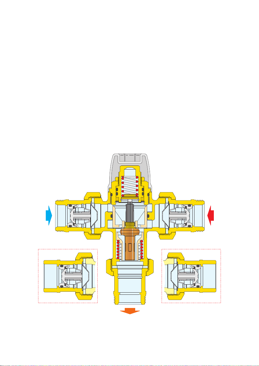
Operating Principle
COLD
HOT
MIXED
A thermostatic mixing valve mixes hot and cold water in such a way as to maintain constant set
temperature of the mixed water at the outlet.
A thermostatic element is fully immersed into the mixed water. This element then contracts or
expands causing movement of the piston, closing either the hot or cold inlets, regulating the
flow rates entering the valve.
If there are variations of temperature or pressure at the inlets, the internal element automatically
reacts to restore the original temperature setting.
Thermal shutoff
In the event of a failure of either the hot or cold supply, the piston will shut off, stopping water
discharging from the mixed water outlet.
The Caleffi valve requires a minimum temperature differential from hot inlet to mixed water outlet
of 18°F (10°C) to ensure the correct operation of the thermal shutoff feature.
Sweat version
3
Page 4
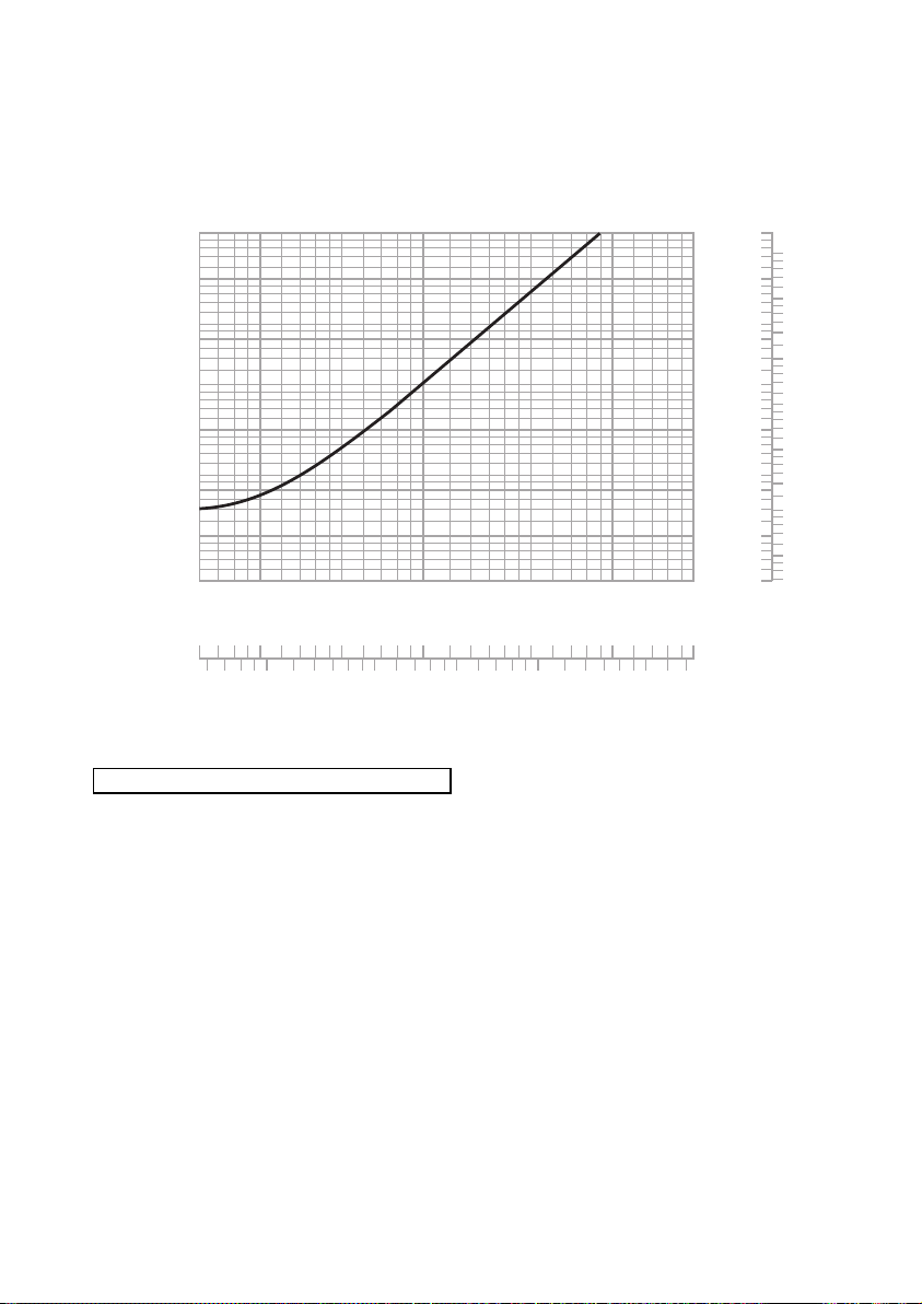
Flow rate graph
10
0.1
2
5
1
0.2
0
.
3
0.
5
20
50
∆p (psi)
G (l/min) (
gpm
)
10
2
3
5
2
0
0
.
1
1
0
.
2
0
.
3
0.
5
(psi) (bar)
10
2
3
5
2
0
1
0.5
10
2
5
2
0
0.01
0
.
1
0
.
02
0
.
03
0
.
05
1
.
0
0
.2
0.3
0
.
5
4
0
.4 0.4
4
0.0
4
0
.4
0.3
1/2", 3/4", 1" • Cv= 2 • Kv=1.7 (m3/h)
Flow rate-use
The Caleffi 5213 series is a thermostatic mixing valve suitable for single or multiple point of
use applications in accordance with installation rules and indications specified in ASSE 1070
standards.
The system must be sized taking into account the current legislation with regard to the nominal
flow rate of each outlet.
4
Page 5

8
11
12
9
10
4
6
7
5
2
3
1
VALVE BODY
UNION NUT, Quantity 3 per valve
UNION WASHER, Quantity 3 per valve
INLET PORT MALE TAILPIECE
WITH INTEGRAL CHECK VALVE
Quantity 2 per valve
INLET PORT CONIC FILTER,
Quantity 2 per valve
TEMPERATURE SPINDLE LOCKING NUT
FLOW CONVEYOR
THERMOSTATIC ELEMENT
'O' RING SEAL
LOWER SPRING
UPPER BODY
PROTECTIVE CAP
13
OUTLET PORT TAILPIECE,
Quantity 1 per valve
4a
'O' RING SEAL
9118
7
6
3
5
4
1
2
10
9 10 12
4a
12
13
11
Exploded diagram
B
5
Sweat version
Page 6

Fittings table
1/2” 3/4” 1”
Item Item Item Q.ty NPT Sweat NPT Sweat NPT Sweat
number description per Valve 521342A 521349A 521352A 521359A 521362A 521369A
9 Union Washer 3 R50055
10 Union Nut 1” 3 R61008/C
Inlet Male Tailpiece
11
with Check Valve
12 Inlet conic filter 2 R52429
13 Outlet Tailpiece 1 R31981 NA10002 R31901A NA10003 59817A* 59834A*
*Tailpiece fitting with integral union nut - 1" NPT and Sweat models require only 2 separate 1" union nuts (item 10)
Installation
The following instructions must be read prior to the installation of a Caleffi valve 5213 series. The
installer should also be aware of his responsibility and duty of care to ensure that all aspects of the
installation comply with current regulations and legislation.
The Caleffi 5213 series should be installed using the appropriate Standard, Code of Practice and
legislation applicable to each state and following the details in this manual.
The Caleffi 5213 series must be installed by a licensed plumber.
Prior to the installation of the Caleffi 5213 series valve, the system must be checked to ensure that the
system operating conditions fall within the recommended operating range of the valve, i.e.
verify supply temperatures, supply pressures, risk assessments, etc.
The supply system into which the Caleffi 5213 series is to be installed must be thoroughly flushed and
cleaned to remove any debris which may accumulate during the installation. Failure to remove any
debris will affect the performance and the manufacturer’s warranty on the product.
In areas that are subject to high levels of aggressive water, provision must be made to treat the water
prior to it entering the valve.
The valve can be installed in any position, whether vertical or horizontal. It is essential that the access
to the valve is not obstructed for future maintenance that may be required to the valve or associated
fittings.
It is essential that when the installation is designed and/or installed, all current legislation is noted, e.g.
the maximum distance from the outlet of the valve to any terminal fitting.
The connecting hot and cold water supplies must be connected to the valve strictly in accordance
with the indications on the body of the valve.
The inlets of the valves are clearly marked with the letter H (Hot) and C (Cold).
The outlet is marked with the word MIX.
Where one or both the incoming supply pressures are excessive, a Caleffi pressure reducing valve
should be fitted to reduce the pressure(s) within the limits.
Any thermostatic mixing valve must be installed with isolating valves, line strainers and check valves
at both the inlets. Isolating valves are required so that the water supply to the valve can be isolated
in the event that servicing is required. Strainers are required to prevent debris from entering the valve.
Check valves are required to both hot and cold inlets to prevent cross-connection.
The Caleffi 5213 series is supplied complete with the check valves at the hot and cold inlets.
The check valve of the sweat version must be dismantled from the tail piece before soldering and then
reassembled.
To ensure that the performance of the Caleffi 5213 series valve is maintained (in the event of cold
water failure), the temperature of the hot water supply at the point of entry to the valve must be a
minimum of 18°F higher than the set mixed water discharge temperature.
The pipework to and from the valve must not be used to support the weight of the valve.
If the valve is not installed correctly, it will not function correctly and may put the user in danger.
2 59893A 59904A 59840A 59905A 59894A 59906A
6
Page 7

Installation diagram
Pressure
reducing valve
(if required)
Isolating
valve
Isolating
valve
Strainer
& check
valve
Strainer
& check
valve
T
Pressure
reducing valve
(if required)
Temperature
limiting valve
(if required)
HOT SUPPLY COLD SUPPLY
MIXED
OUTLET
MIX
MIX
HOT
COLD
MIX
MIX
HOT
COLD
Point of use
Multiple use
Multiple use with sensor faucet
7
Page 8

Commissioning
Upon completion of the installation, the valve should be tested and commissioned as per the
procedure outlined below or as specified by the local authority.
The following instructions should be read and understood prior to commissioning the Caleffi
5213 series valve. If, under any circumstances, there are aspects of the installation/system
which do not comply with our requirements or the specifications as laid down, the valve must
not be put into service until the installation/system does comply.
1) Ensure that the system is throughly clean and free from debris prior to commissioning the
thermostatic mixing valve.
2) We recommend that the commissioning of temperatures is carried out using a suitably
calibrated and accurate digital thermometer.
The valve is commissioned by measuring the mixed water temperature at the outlet.
3) In accordance with the anti-scald requirements, water installation shall deliver hot water at
the outlet of the sanitary fixtures used primarily for personal hygiene purposes at a
temperature not exceeding:
· 120°F (49°C) or as specified by authority having jurisdiction.
4) The temperature at the outlet of each valve must be set taking into consideration any
fluctuations which may occurr within the system due to simultaneous demand.
5) Once the supply temperatures are stabilised and the normal operating conditions are
established, the valve can be commissioned. Due to the unique design of the cap, the
temperature setting can be adjusted by removing the cap from the valve body and
reversing the cap onto the temperature adjustment spindle. We suggest that the following
sequence is followed when commissioning the valve.
a) Set the mixed water discharge temperature to the required temperature.
b) Measure and record the temperature of hot and cold water supplies at the
connections to the valve.
c) Measure and record the temperature of the water discharging from the largest and
smallest volume draw off points.
d) Perform the thermal shut-off test. Isolate the cold water supply to the Caleffi valve
and monitor the mixed water temperature. The outlet flow should quickly cease
flowing.
e) Measure and record the maximum mixed water temperature. The temperature
should not exceed the temperature allowed by the applicable standard or code of
practice for each state.
f) Restore the cold water supply to the valve and measure and record the outlet
temperature after the mixed water temperature has stabilised. The final temperature
found during this test should not exceed the permitted values +3°F.
6) Once the desired temperature has been reached, the adjustment spindle can be locked in
position using the locking nut supplied with the valve.
7) Once the desired temperature is established, remove the cap from the temperature
adjustment spindle and secure the head back on to the valve into its original position to
prevent tampering by unauthorised persons.
We recommend that the above information is recorded in the Commissioning Report and
updated on the Service Report when any work is carried out on the valve.
8
Page 9

Temperature adjustment
1
2
3
View of temperature adjustment
Fitting temperature adjustment cap
Temperature adjustment cap in place
4
Locking adjustment spindle with locking nut
9
Page 10

Maintenance
In service tests should be carried out regularly to monitor and record the performance of the
valve. Deterioration in performance can indicate the need for servicing of the valve and/or
water supply. If, during these tests, the mixed water temperature has changed significantly
from the previous test results, record the change before re-adjusting the mixed water
temperature. If the final mixed water temperature is greater than the permitted values, we
recommend that the details quoted in Installation and Commissioning sections are verified and
that service work is required.
We recommend that at least every 12 months, or more frequently if the need arises, that the
following aspects are checked to ensure that the optimum performance level of the valve is
maintained.
With reference to the exploded diagram on page 5:
1) On the Caleffi 5213 series valves, the inlet conic filters (12) on both the hot and cold water
supplies can be removed for cleaning by unscrewing the inlet union nuts and carefully
pulling apart the connecting pipework.
2) The built in check valves (11) on the Caleffi 5213 series valves can be accessed in a similar
way to 1) to ensure freedom of operation and correct working.
3) In case of service work, the internal components of the valve can be dis-assembled for
cleaning and discaling:
a) Remove the cap of the valve (1) and the locking nut (2)
b) Remove the upper body (3) using a suitable spanner
c) Remove parts 5-7 noting the correct orientation
d) Remove all signs of scale and dirt from the internal part using a suitable de-scaling
solution.
e) Re-assemble all the components
Once the serviceable items have been dealt with we recommend that the commissioning
details as stated previously are repeated ensuring that a suitably accurate thermometer is
used.
Should the valve still not function correctly, it may be necessary to replace the thermal element
or other components. Refer to spare part kits and contact Service Department for details and
advices.
Spare parts
With reference to the exploded diagram, the spare parts are available on request for Caleffi
5213 series valves, see table on page 6.
10
Page 11

Troubleshooting
Under normal operating conditions the Caleffi 5213 series thermostatic mixing valve will
provide a very high level of performance. However, in some circumstances, when our
maintenance plan is not followed, the following problems may arise.
Symptom
Hot water at the cold taps
Fluctuating mixed water
temperature
Erratic flow of water from
the valve
No flow of water from the
valve
Cause
a) Operation of the insert
check valve is hindered;
check valve is not
sealing correctly.
b) Check valves not fitted.
a) Erratic supply
temperatures at the
inlets of the valve.
b) Starvation of the water
supplies at the inlets
of the valve.
c) Incorrect commissioning
of the valve.
a) Insufficient water
supplies.
b) Fluctuations in supply
pressures/temperatures.
c) Adverse effect created
by other draw off points
on the system.
a) In-line filters blocked.
b) Insufficient supply
pressures.
c) Debris obstructing valve
operation.
Corrective action
· Replace faulty check
valves
· Restore inlet conditions
within the limits of the
valve.
· Stabilize inlet supply
conditions.
· Clean filters.
· Restore inlet supplies.
· Clean debris or scale
from valve.
Valve does not shutoff
when tested
a) Installation not in
accordance with our
recommendations.
b) The minimum
temperature differential
not achieved.
c) Internal mechanism
hindered by debris.
11
· Install as oulined in the
instructions.
· Raise hot water
temperature.
· Clean debris or scale
from valve.
Page 12

CALEFFI
Caleffi North America, Inc.
3883 West Milwaukee Road
Milwaukee, WI 53208
T: 414.238.2360 F: 414.238.2366
 Loading...