

Page 1
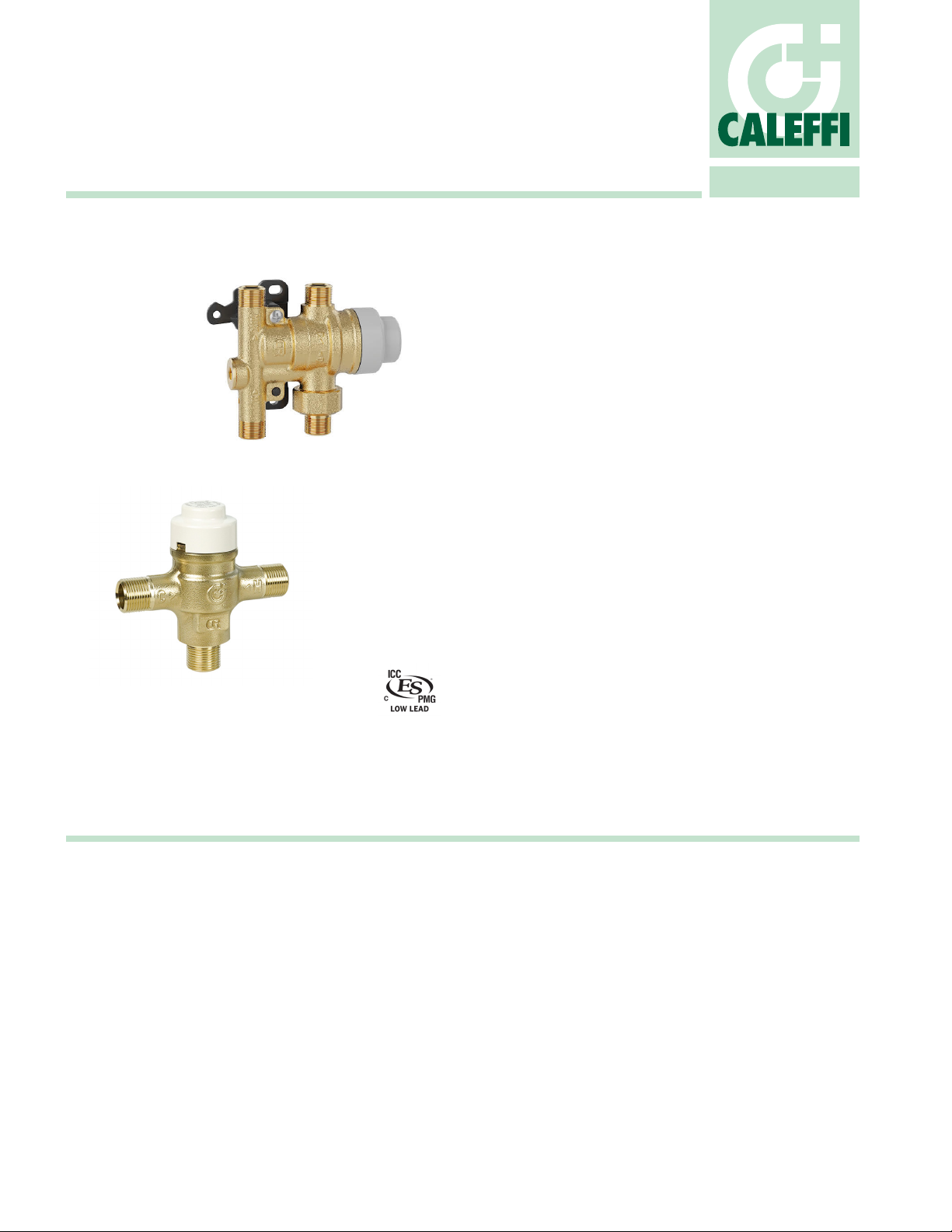
SinkMixer™ Scald Protection
Thermostatic Mixing Valve
5212 series
ASSE 1070
NSF/ANSI/CAN 61
NSF/ANSI/CAN 372
01364/24 NA
Replaces 01364/22 NA
Function
The Caleffi SinkMixer™ thermostatic mixing valve ensures that users are
safeguarded against scalding water temperature conditions in applications
such as sinks and lavatories. The SinkMixer is most critical in hospitals,
schools, and nursing homes, where precise water temperature control
is essential for the safety of vulnerable individuals. In accordance with
American and Canadian product safety standards, the valve functions to
control and limit the mixed outlet water temperature up to 120 ºF. In the
event of cold water supply failure the valve will rapidly reduce outlet flow
to prevent against scalding conditions from fluctuating hot water supply
conditions. The SinkMixer is equipped with integral check valves on both
supply inlets to prevent against cross flow conditions .
The SinkMixer comes in two configurations: 3-port and 4-port. The 3-port
compact configuration is designed for single-pipe installations in mind
where only a singular tempered water is supplied to the fixture. The 4-port
configuration is meant for fixtures requiring both hot and cold sources
without requiring a brass T or additional piping. The 3-port configuration
includes a compression fitting kit for hard pipe applications, while the
4-port configuration comes with a mounting bracket and an optional cold
port plug and compression fittings kit for hard pipe installations.
The Caleffi SinkMixer family complies with ASSE 1070/ASME A112.1070/
CSA B125.70 performance requirements for water temperature limiting
devices. Certified and listed by ICC-ES, PMG File 1358. Complies with
low lead and lead free material requirements of NSF/ANSI/CAN 61 and
NSF/ANSI/CAN 372 for use in potable water systems. Certified and listed
by ICC-ES, PMG File 1512 and PMG File 1360 respectively. Certified
for installation and use in compliance with UPC, IPC, NRC, and NPC
plumbing codes. Certified and listed by ICC-ES, PMG File 1358.
Product range
521201A
521201AP
521204A
Technical specications
Materials:
Valve body, regulating spindle, spring holder, cold inlet union nut:
forged low-lead* brass
Internal shutter: polysulfone
Hot inlet strainer: AISI 304 stainless steel
Spring: AISI 302 stainless steel
Seals: Peroxide-cured EPDM
Cover: ABS white
Mounting bracket and adjustment key: Polyamide Nylon
* Meets the “lead free” requirement of Section 1417 of the Safe Drinking Water Act (SDWA).
This product has a weighted average lead content of less than 0.25% for its wetted surfaces
contacted with consumable water.
Performance
Temperature adjustment range: 95–120 °F (35–50 °C)
Temperature set:
must be commissioned on site to achieve desired temperature
Temperature stability: ±3 °F (±2 °C)
Cold inlet temperature: Minimum 40 °F (5 °C); Maximum 85 °F (30 °C)
Hot inlet temperature: Minimum 120 °F (50 °C); Maximum 195 °F (90 °C)
Factory Setting: 113 °F (45 °C)
Maximum operating differential pressure:
Static: 150 psi (10 bar); Dynamic: 70 psi (5 bar)
4-port SinkMixer scald protection thermostatic mixing valve with compression union connections.......................................size 3/8"
4-port SinkMixer scald protection thermostatic mixing valve with compression union connections
with plug for cold water outlet and copper compression fittings kit for hard piping installations...................................size 3/8”
3-port SinkMixer scald protection thermostatic mixing valve, includes compression fittings kit............................................size 3/8”
Minimum operating differential pressure (dynamic): 1.5 psi (0.1 bar)
Maximum unbalanced dynamic supply (hot/cold or cold/hot): 2:1
Minimum temperature differential between hot water inlet and mixed
water outlet to ensure thermal shutoff function: 18 °F (10 °C)
Minimum temperature differential between mixed water outlet and cold
water inlet to ensure stable operation: 9 °F (5 °C)
Minimum flow rate for optimum operation: 0.35 gpm (1.3 l/min)
Maximum flow rate for optimum operation: 2.3 gpm (8.5 l/min)
Connections
Main connections: 3/8” compression
Certications
1. ASSE 1070/ASME A112.1070/CSA B125.70, CSA B125.3, UPC,
IPC, IRC and NPC compliance for use in accordance with U.S. and
Canadian plumbing codes. Certified and listed by ICC-ES, PMG File 1358.
2. NSF/ANSI/CAN 61, Drinking Water System Components for use in
potable water systems. Certified by ICC-ES, PMG File 1512.
3. NSF/ANSI/CAN 372, US and Canadian Low-Lead and Lead-Free
materials contents laws for drinking water system components.
Certified by ICC-ES, PMG File 1360.
Page 2
1 2 3 4
ABCDEF
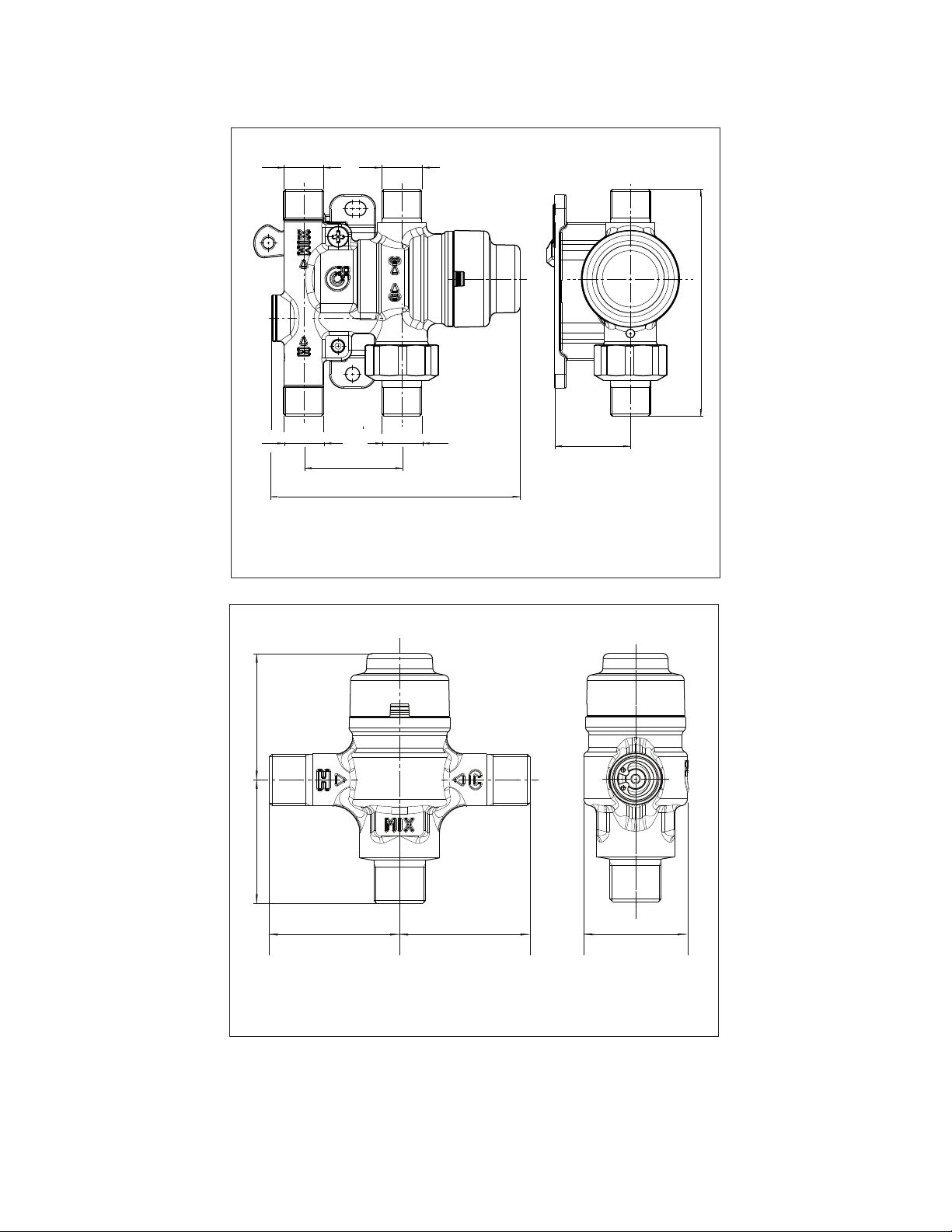
Dimensions
1-3/8”
1-3/8”
1-7/16”
1-7/16”
3/8” compression, 3 ports
1-1/8”
3/8” compression* 3/8” compression*
3 3/16”
3/8” compression* 3/8” compression*
1 3/8”
3 1/2”
Code 521201A, AP** 0.5 lb /0.3 kg
* Actual thread is 9/16” - 24 UNEF.
**AP includes a plug for cold water outlet and a bag with 4 nuts and 4 ferrules for hard
pipe installations.
1 1/16”
* Actual thread is 9/16” - 24 UNEF.
**521204A package includes a bag with 3 nuts and 3 ferrules.
Code 521204A 0.5 lb /0.3 kg
Page 3
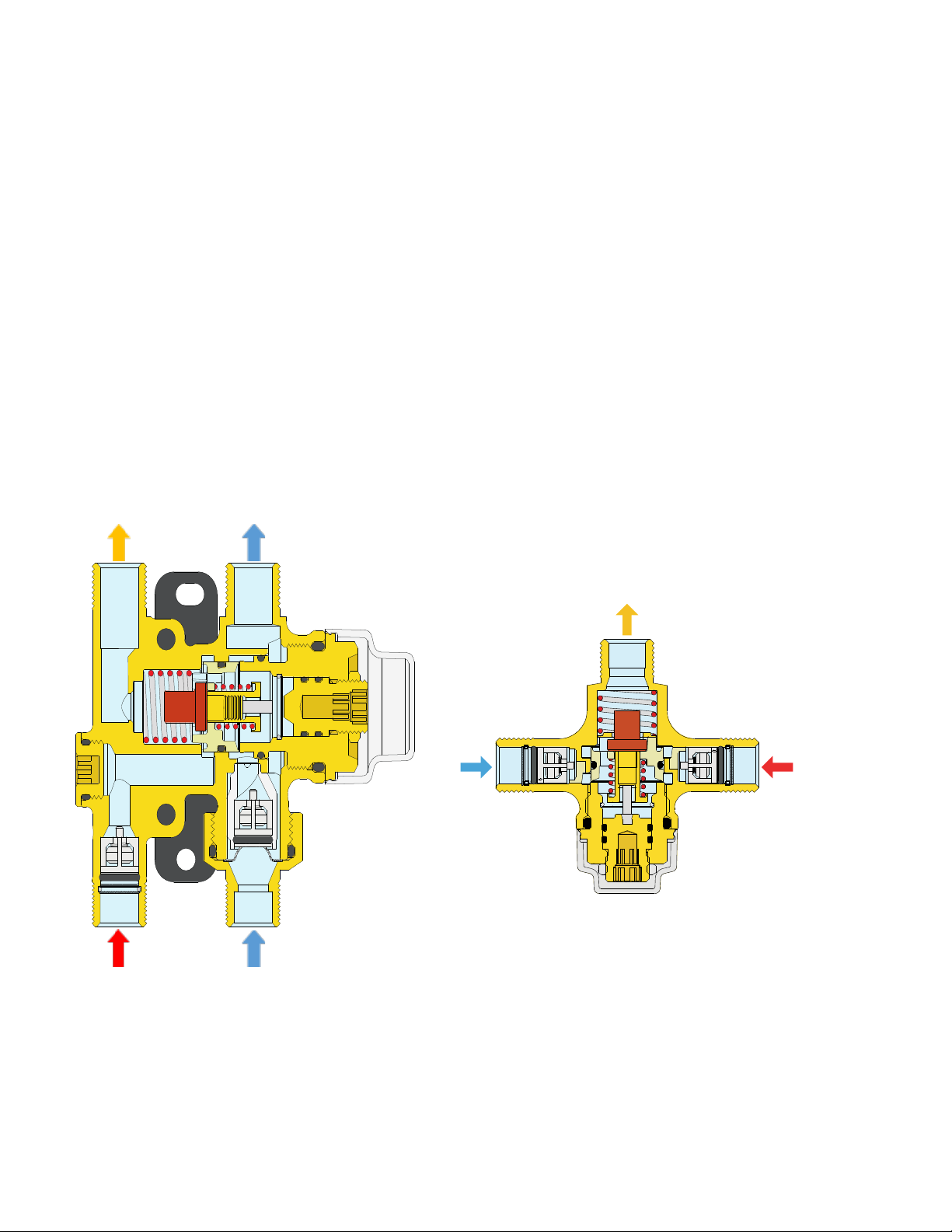
Operating principle
Use
The thermostatic mixing valve maintains a constant outlet temperature
by adjusting the ratios of hot and cold water automatically. Its immersed
thermostatic element contracts or expands, moving the piston to
regulate flow rates from the hot or cold inlets to achieve the desired
outlet temperature. It responds to fluctuations in temperature or
pressure at the inlets by automatically adjusting to maintain the set
temperature. If the cold supply fails, the piston fully expands, halting
water discharge from the mixed outlet.
Thermal shutoff
In the event of a failure of the hot supply port, the piston closes the cold
supply port. Similarly, if the cold water supply fails, the piston closes
the hot supply port. The Caleffi SinkMixer scald protection thermostatic
mixing valve requires a minimum temperature differential from hot inlet
to mixed water outlet of 18 °F (10 °C) to ensure the correct operation
of the thermal shutoff feature.
MIX OUTLET
COLD OUTLET
The Caleffi SinkMixer thermostatic mixing valve is designed for under
sink and under counter applications in accordance with plumbing
codes requirements for installation and performance requirements of
ASSE 1070/ASME A112.1070/CSA B125.70.
Valve and system sizing according to current legislation considering the
nominal flow rate at each outlet is required.
The SinkMixer serves to prevent accidental scalding by ensuring the
outlet water temperature is correctly tempered and limited. Verification
of desired outlet temperature using a thermometer at the faucet is
recommended.
HOT INLET
Code 521201A, AP
COLD INLET
COLD INLET
MIX OUTLET
HOT INLET
Code 521204A
Page 4
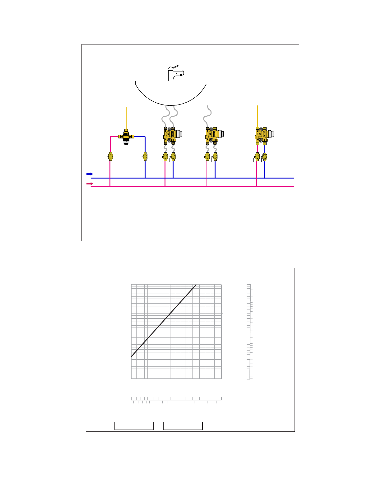
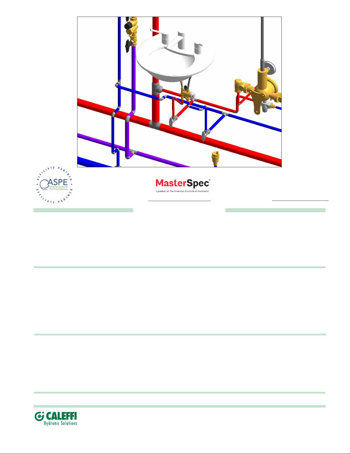
Application diagram
Point of use
Flow curve
521204A
COLD
HOT
521201A
p (psi )
Δ
20
10
5
4
3
2
1
0.5
0.4 0.4
0.3
0.2
0.1
.5
0.3
0
1
2
521201AP
(psi) (bar
20
10
5
4
3
2
1
0.5
0.3
0.2
0.1
)
5
gpm
1.0
0.5
0.4
0.3
0.2
0.1
0.05
0.04
0.03
0.02
0.01
)
2
Cv= 0.52
Flow should never exceed standards for pipe size and materials.
5
Kv= 0.45
10
20
G (l/min)(
Page 5
Installation
Temperature adjustment (4-port)
The following instructions must be read prior to the installation of a Caleffi
SinkMixer thermostatic mixing valve. The installer should also be aware of
his responsibility and duty of care to ensure that all aspects of the installation
comply with current regulations and legislation. The Caleffi SinkMixer should
be installed using the appropriate standard, code of practice and legislation
applicable to each state and following the details in this manual. The Caleffi
SinkMixer series must be installed by a licensed plumber.
Prior to the installation of the valve, the system must be checked to ensure
that the system operating conditions fall within the recommended operating
range of the valve, i.e. verify supply temperatures, supply pressures, risk
assessments, etc.
The supply system into which the Caleffi SinkMixer is to be installed must
be thoroughly flushed and cleaned to remove any debris which may
accumulate during the installation. Failure to remove any debris will affect
the performance and the manufacturer’s warranty on the product. In areas
that are subject to high levels of aggressive water, provision must be made
to treat the water prior to it entering the valve.
The 4-port valve is recommended to be installed in a position oriented with
the cover to the right with cold inlet/outlet on the right side (allowing direct
connection to the sink’s cold water inlet fitting) resulting in the hot inlet/mix
outlet on the left aligning direct to the hot water inlet sink fitting. The 3-port
valve is recommended to be installed with the MIX port up. It is essential that
the access to the valve is not obstructed for future maintenance that may be
required to the valve or associated fittings.
It is essential that when the installation is designed and/or installed, all current
legislation is noted, e.g. the maximum distance from the outlet of the valve
to any terminal fitting.
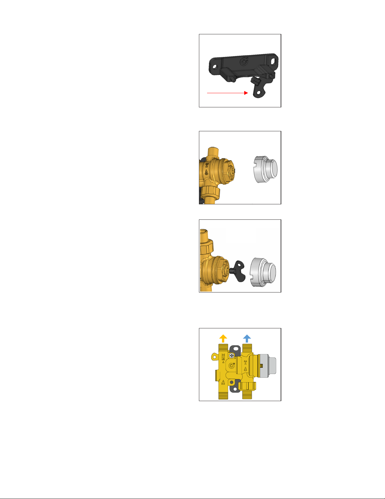
1
Remove 1/4” hex key from mounting
bracket.
2
Remove white cap.
3
The connecting hot and cold water supplies must be connected to the valve
strictly in accordance with the indications on the body of the valve. The inlets
of the valves are clearly marked with the letter H (Hot) and C (Cold). The
outlet is marked with the word MIX. The valve has male 3/8” compression
threads for conection to standard 3/8” compression faucet connectors and
stops.
Where one or both the incoming supply pressures are excessive, a Caleffi
pressure reducing valve should be installed to reduce the pressure(s) within
the limits.
The Caleffi SinkMixer valve is supplied complete with the check valves at the
hot and cold inlets.
Mount the 4-port SinkMixer valve to the wall underneath the sink with
black plastic mounting bracket supplied with valve but not attached. Use
mounting screw to attach the mounting bracket to the valve to meet the
orientation described above. Break off the adjustment key for adjusting the
termperature, see commisioning section.
To ensure that the performance of the Caleffi SinkMixer valve is maintained
(in the event of cold water failure), the temperature of the hot water supply at
the point of entry to the valve must be a minimum of 18 °F higher than the
set mixed water discharge temperature.
If the valve is not installed correctly, it will not function correctly and may put
the user in danger.
For single-pipe fixtures (tempered water only), code 521201AP comes
complete with a plug/nut for the valve cold outlet port.
a 5-pack of plugs/nuts to plug cold outlet port when installing code
521201A (unit coming without this plug/nut) in single pipe fixture
undersink piping. Code 521201AP also includes a copper compression
fittings kit for hard pipe installations.
Code NA10741 is
Adjust temperature setting with 1/4”
hex key. After adjustment, lock the
temperature with locking nut.
4
Replace tamper proof cap and store
key in safe place.
NOTE: Follow steps 2, 3 and 4 for
the 3-port version.
MIX
COLD
Page 6
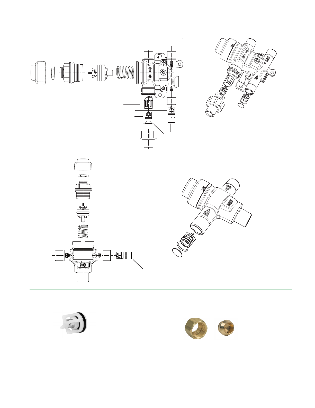
Replacement parts
Code 521201A, AP
Code 521204A
check valve
holder
check valves
strainers
check valves
Replacement check valve and strainers for
521201A under sink thermostatic mixing valves.
F0001270.........check valve and two strainers,
one set for the cold inlet port and one set for the
hot inlet port.
strainers
5-pack of plugs/nuts to plug the valve cold outlet
port when using code 521201A with a single-pipe
fixture.
NA10741.......plug/nut 3/8" compression (5-pack)
Page 7
Find us in
https://get.caleffi.info/specpoint
find BIM Revit files and system templates at
https://bim.caleffi.com/en-us
SPECIFICATION SUMMARY
521201A
Scald Protection point of use 4-port thermostatic valve certified to ASSE 1070, NSF/ANSI 372-2011 Drinking Water Systems
Components-Lead Content Reduction of Lead in Drinking Water, California Health and Safety Code 116875 S.3874, and
NSF/ANSI/CAN 61-2018, Drinking Water System Components – Health Effects. Threaded 3/8” compression connection. Lowlead forged brass body (<0.25% Lead content). Polysulfone shutter. Seal in Peroxide-cured EDPM. Stainless steel spring.
Maximum working temperature 195 °F (90 °C). Setting range from 95–120 °F (35–50 °C). Tolerance of ±3 °F (±2 °C).
Maximum working pressure 150 psi (10 bar). Maximum unbalanced dynamic supply pressure 2:1. Tamper-proof setting lock
and check valves on the inlets.
521201AP
Scald Protection point of use 4-port thermostatic valve certified to ASSE 1070, NSF/ANSI 372-2011 Drinking Water Systems
Components-Lead Content Reduction of Lead in Drinking Water, California Health and Safety Code 116875 S.3874, and
NSF/ANSI/CAN 61-2018, Drinking Water System Components – Health Effects. Threaded 3/8” compression connection. Lowlead forged brass body (<0.25% Lead content). Polysulfone shutter. Seal in Peroxide-cured EDPM. Stainless steel spring.
Maximum working temperature 195 °F (90 °C). Setting range from 95–120 °F (35–50 °C). Tolerance of ±3 °F (±2 °C).
Maximum working pressure 150 psi (10 bar). Maximum unbalanced dynamic supply pressure 2:1. Tamper-proof setting
lock and check valves on the inlets. Includes plug/nut for cold water outlet port for use with single-fixture fixtures providing
tempered water only and copper compression fittings kit for hard pipe installations.
521204A
Scald Protection point of use 3-port thermostatic valve certified to ASSE 1070, NSF/ANSI 372-2011 Drinking Water Systems
Components-Lead Content Reduction of Lead in Drinking Water, California Health and Safety Code 116875 S.3874, and
NSF/ANSI/CAN 61-2018, Drinking Water System Components – Health Effects. Threaded 3/8” compression connection. Lowlead forged brass body (<0.25% Lead content). Polysulfone shutter. Seal in Peroxide-cured EDPM. Stainless steel spring.
Maximum working temperature 195 °F (90 °C). Setting range from 95–120 °F (35–50 °C). Tolerance of ±3 °F (±2 °C).
Maximum working pressure 150 psi (10 bar). Maximum unbalanced dynamic supply pressure 2:1. Tamper-proof setting lock
and check valves on the inlets.
We reserve the right to make changes and improvements to the products and related data in this publication, at any time and without prior notice.
The technical brochure on www.caleffi.com always has the most up-to-date version of the document, which should be used for technical verification.
Caleffi North America, Inc.
3883 W. Milwaukee Road
Milwaukee, WI 53208
Tel: 414-238-2360 · Fax: 414-238-2366
Technical Support: 414-338-6338 / [email protected]
[email protected] · www.caleffi.com
© Copyright 2024 Caleffi North America, Inc.
 Loading...