

Page 1
AngleMix™ Thermostatic mixing valve
NA10618
www.caleffi.com
© Copyright 2018 Caleffi
Function
The Caleffi AngleMix™ 520 series thermostatic mixing valve is used
in systems producing domestic hot water and easily mounts to the
top of water heaters. The mixed temperature outlet is inline with
the hot water inlet, facilitating trouble-free connection and reducing
space required for installation. The AngleMix maintains the desired
output temperature of the mixed water supplied at a constant set
value compensating for both temperature and pressure fluctuations
of the incoming hot and cold water. The mixing valve also features a
thermal shut-off function that operates in the event of a cold water
supply failure at the inlet. Also available as body only, for a wide
variety of separately-ordered end connections, the angle style body
design offers improved fluid dynamics for better performance and
reduces installation labor and materials, eliminating a piping elbow
in typical installations.
The valve has been specifically certified to ASSE 1017 and Low
Lead Plumbing Law by ICC-ES.
Product range
5205__A series: Adjustable three-way thermostatic mixing valve with mixed outlet temperature gauge
and angle body............................................................connections ¾” press and sweat union
5205__AC series: Adjustable three-way thermostatic mixing valve with mixed outlet temperature gauge,
angle body with inlet port check valves............................connections ¾” press and sweat union
520051A: Adjustable three-way thermostatic mixing valve, angle style body only for field installed
connection fittings and temperature gauge, order separately.........connections 1” male union
Technical specication
Materials
-Valve body: DZR low-lead brass
-Shutter, seats and slide guides:
PSU
-Springs: stainless steel
-Seals: EPDM
-Adjustment knob: ABS
Performance
Suitable fluids: water
Setting range: 95–150° F (35–65° C)
Tolerance: ±3° F (±2° C)
Max. working pressure (static): 150 psi (10 bar)
Max. working pressure (dynamic): 75 psi (5 bar)
Max. hot water inlet temperature: 195°F (90°C)
Max. inlet pressure ratio (H/C or C/H) for optimal
performance: 2:1
Min. temperature difference between hot
water inlet and mixed water outlet for optimal
performance: 18°F(10°C)
Min. flow to ensure optimal performance:
0.5 gpm (2 L/min)
Mixed outlet temperature gauge:
2” diameter
Scale from 30—210º F
Certifications:
1. ASSE 1017/CSA B125.3, certified by ICC-ES,
file PMG-1357.
2. NSF/ANSI 372-2011, Drinking Water System
Components-Lead Content Reduction of Lead in
Drinking Water Act, California Health and Safety
Code 116875 S.3874, Reduction of Lead in Drinking
Water Act, certified by ICC-ES, file PMG-1360.
520 Series
1
Page 2
SAFETY INSTRUCTION
This safety alert symbol will be used in this manual to draw attention to safety related
instructions. When used, the safety symbol means ATTENTION! BECOME ALERT! YOUR
SAFETY IS INVOLVED! FAILURE TO FOLLOW THESE INSTRUCTIONS MAY RESULT
IN A SAFETY HAZARD.
WARNING: This product can expose you to chemicals including lead, which
is known to the State of California to cause cancer and birth defects or other
reproductive harm. For more information go to www.P65Warnings.ca.gov.
CAUTION: All work must be preformed by qualified personnel trained in the
proper application, installation, and maintenance of systems in accordance
with all applicable codes and ordinances.
CAUTION: If the thermostatic mixing valve is not installed, commissioned
and maintained properly, according to the instructions contained in this
manual, it may not operate correctly and may endanger the user.
CAUTION: Make sure that all the connecting pipework is water tight.
CAUTION: When making the water connections, make sure that the pipwork
connecting the AngleMix thermostatic mixing valve is not mechanically
overstressed. Over time this could cause breakages, with consequent water
losses which, in turn, could cause harm to property and/or people.
CAUTION: Water temperatures higher than 100ºF (38ºC) can be dangerous.
During the installation, commissioning and maintenance of the AngleMix
thermostatic mixing valve, take the necessary precautions to ensure that such
temperatures do not endanger people.
CAUTION: To prevent any damage which will cause the electronic mixing
valve to not operate correctly, treat highly aggressive water before entering
the thermostatic mixing valve. Be sure water hardness is less than 10
grains.
CAUTION: If installed in an ASSE 1017 application, check valves shall be
used.
LEAVE THIS MANUAL WITH THE USER.
2
Page 3

CONSIGNE DE SÉCURITÉ
Ce symbole d'avertissement servira dans ce manuel à attirer l'attention sur la sécurité concernant
instructions. Lorsqu'il est utilisé, ce symbole signifie.
ATTENTION! DEVENEZ ALERTE ! VOTRE SÉCURITÉ EST EN JEU ! NE PAS SUIVRE CES
INSTRUCTIONS PEUT PROVOQUER UN RISQUE DE SECURITE.
AVERTISSEMENT:
plomb, qui est connu dans l’État de Californie pour causer le cancer, dommages à la
naissance ou autre. Pour plus d’informations rendez-vous www.P65Warnings.ca.gov.
ATTENTION: Tous les travaux doivent être effectués par du personnel qualifié
formé à la bonne application, installation et maintenance des systèmes
conformément aux codes et règlements locaux.
ATTENTION: Si le réducteur de pression, termostatico regolabile, n'est pas installé,
mis en service et entretenu correctement, selon les instructions contenues dans ce
manuel, il peut ne pas fonctionner correctement et peut mettre en danger l'utilisateur.
ATTENTION: S'assurer que tous les raccordements sont étanches.
ATTENTION: Lorsque vous effectuez les raccordements d'eau, assurez-
vous que la tuyauterie reliant le AngleMix termostatico regolabile n'est pas
mécaniquement des overstressed. Au fil du temps, ceci pourrait causer des
ruptures, avec pour consequence des pertes en eau qui, à leur tour, peuvent
causer des dommages à la propriété et/ou les gens.
ATTENTION: Les températures de l'eau supérieure à 100°F (38°C) peut
être dangereux. Au cours de l'installation, mise en service et l'entretien
de le réducteur de pression, le AngleMix termostatico regolabile, prendre les
precautions nécessaires afin de s'assurer que de tells températures ne
compromettent pas les gens.
Ce produit peut vous exposer à des produits chimiques comme le
ATTENTION: Pour prévenir tout dommage qui provoque le mitigeur
électronique à ne pas fonctionner correctement, le traitement de l’eau très
agressive avant d’entrer dans la termostatico regolabile. Assurez-vous que la
dureté de l’eau est inférieure à 10 grains.
ATTENTION: S’il est installé dans un pays de ASSE 1017 application, vérifiez les
robinets doivent être utilisés.
LAISSEZ CE MANUEL AVEC L’UTILISATEUR
3
Page 4
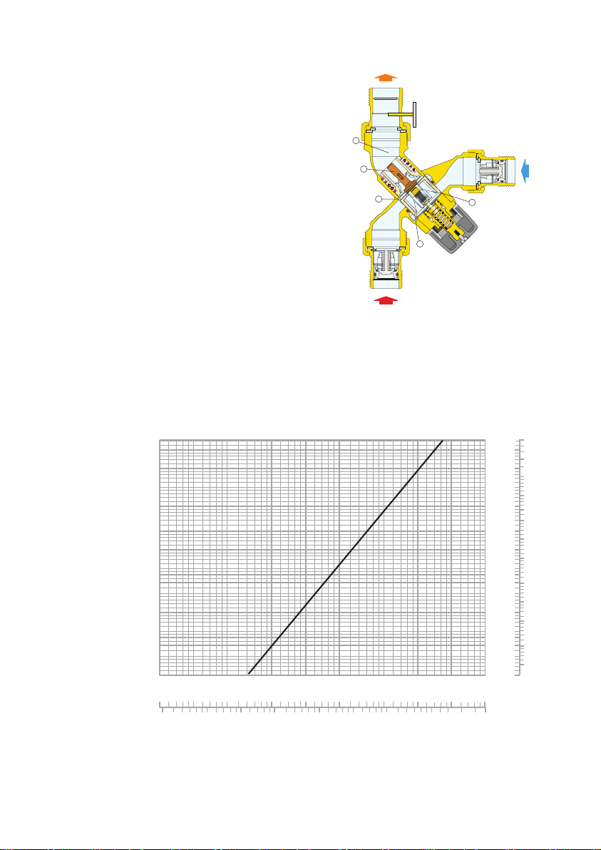
Operating principle
MIXED
Kv = 1.7
(psi) (bar)
0.001
0.002
0.003
0.005
Cv = 2.0
0.004
The thermostatic mixing valve mixes the hot
and cold water at the inlets to maintain constant
mixed water at the desired set temperature. A
thermostatic sensor (1) is fully immersed in
the mixed water outlet passage (2) which,
as it expands or contracts, continuously
establishes the correct proportion of hot and
cold water entering the valve. The regulation
of these flows is by means of a piston (3)
sliding in a cylinder between the hot and cold
water passages. This controls the passage of
hot (4) or cold (5) water at the inlet. If the inlet
temperature or pressure changes, the internal
element automatically reacts to restore the set
temperature at the outlet. The AngleMix 520
series point of distribution mixing valve is an
angled configuration for easy installation to
most water heaters for direct mounting to the
top pipe connections.
Flow curve
161
115
46
23
11.5
9.2
6.9
4.6
2.3
1.15
0.92
0.69
0.46
0.23
0.115
0.092
0.069
0.046
0.023
.05
0
0.02
1
.
.2
0
0
0.05
0.5
0.1
0.2
2
1
4
3
HOT
5
70
50
20
10
0
2
1
0.5
5
10
20
10
50
50
2
70
100
140
190
5
4
3
2
1
0.5
0.4
0.3
0.2
0.1
0.05
0.04
0.03
0.02
0.01
)
gpm
G (l/min) (
5.0
2.0
1.0
0.5
0.4
0.3
0.2
0.1
0.05
0.04
0.03
0.02
0.01
COLD
4
Page 5

Use
Caleffi AngleMix 520 series thermostatic mixing valves are designed to be installed at the
point of distribution to control the temperature of the domestic hot water distributed in the
downstream network. The 520 series valve cannot be used for tempering water temperature
at fixtures as a point-of-use valve. They are not designed to provide scald protection or chill
protection service. They should not be used where ASSE 1070 devices are required. Wherever
a scald protection feature is required, Caleffi 5213 series high performance mixing valves need
to be installed. For safety reasons, it is advisable to limit the maximum mixed water temperature
to 120°F when anti-scald devices are not used at each fixture.
Construction details
Thermal shut-off
In the event of accidental cold water supply failure, the shutter seals off the hot water passage,
thus preventing the delivery of mixed temperature water. This is only guaranteed when there
is a minimum temperature difference between the inlet hot water and the mixed temperature
water delivery of 18°F.
Body shape
The “L” pattern configuration facilitates installation of the mixing valve. It offers improved
fluid dynamics for better performance and high Cv values with minimum head losses. It also
reduces installation labor by eliminating a piping elbow in typical installations.
Anti-scale materials
The materials used in constructing the mixing valve are designed to eliminate seizing due to
limescale deposits. All functional parts have been made using a special anti-scale material with
low friction coefficient, ensuring long life performance.
Certication
1. ASSE 1017/CSA B125.3, certified by ICC-ES, file PMG-1357.
2. NSF/ANSI 372-2011, Drinking Water System Components-Lead Content Reduction of Lead
in Drinking Water Act, California Health and Safety Code 116875 S.3874, Reduction of Lead in
Drinking Water Act, certified by ICC-ES, file PMG-1360.
5
Page 6

Installation
Before installing a Caleffi AngleMix 520 series three-way thermostatic mixing valve, the system
must be inspected to ensure that its operating conditions are within the range of the mixing
valve, checking, for example, the supply temperature, supply pressure, etc.
Systems where the 520 series thermostatic mixing valve will be installed must be drained and
cleaned out to remove any dirt or debris which may have accumulated during installation.
The installation of appropriately sized filters at the inlet from the main water supply is always
advisable.
Caleffi AngleMix 520 series thermostatic mixing valves must be installed by qualified personnel
in accordance with the diagrams in this brochure, taking into account all current applicable
standards.
Caleffi AngleMix 520 series thermostatic mixing valves can be installed in any position, either
vertical or horizontal, or upside down.
Scan to view
·
520 AngleMix™
The following are shown on the thermostatic mixing valve body:
- Hot water inlet, color red and marked “HOT”.
- Cold water inlet, color blue and marked “COLD”.
- Mixed water outlet, marked “MIX”.
Installation Tip
Locking the setting
Position the handle to the number required with
respect to the index point. Unscrew the head screw,
pull off the handle and reposition it so that the handle
fits into the internal slot of the knob. Tighten the
headscrew.
2
3
1
M
I
N
M
A
X
7
Index Point
Check valve
In systems with thermostatic mixing valves, check valves should be installed to prevent
undesired backflow. In order to prevent undersirable backsiphonage, separate check valves
should be installed in systems with code “520 A” model thermostatic mixing valves (these
models do not contain integral check valves in the hot and cold inlet ports). As a convenience
for easier installations, the Caleffi code “520 AC” model series thermostatic mixing valves
include integral check valves in the hot and cold inlet ports.
NOTE TO INSTALLER: DO NOT TEST FIT OR INSTALL CHECK VALVES BEFORE
SOLDERING. IF INSTALLED, REMOVAL WILL REQUIRE DAMAGING THE CHECK VALVE
AND IT WILL NO LONGER BE USABLE.
6
Page 7

B
C
A
D
2
¾
”
2¾”
Lay length
A
A
HOT
MIX
COLD
30
50
70
90
110
130
150
170
190
210
ºF
Dimensions
Code A B C D Wt. (lb.)
520516A
520516AC
520519A
520519A
Lay length (hot inlet to mix oulet) for press: 59⁄16"; for sweat: 59⁄16”.
3
⁄4" press 4" 8" 413⁄16” 2.8
3
⁄4" press with
inlet checks
3
⁄4” sweat 4” 7½" 47⁄16" 2.8
3
⁄4” press with
inlet checks
4” 11½” 63⁄4” 2.8
4” 10” 6½” 2.8
7
Page 8

Commissioning
The Caleffi AngleMix 520 series thermostatic mixing valve must be commissioned in accordance
with current standards by qualified personnel using temperature measuring equipment. Caleffi
520516A, 520516AC, 520519A and 520519AC with integral outlet port temperature gauge
provide a time-saving temperature setting process to get close to the desired temperature. Use
of a digital thermometer is recommended for confirming the final setting of the mixed water
temperature. After installation, the valve must be tested and commisioned in accordance with
instructions given below, taking into account current applicable standards.
1) Ensure that the system is clean and free from dirt or debris before commissioning the
thermostatic mixer.
2) It is recommended that the temperature is set using a suitable calibrated digital thermometer.
The valve must be commissioned by measuring the temperature of the mixed water emerging
at the point of use.
3) The maximum outlet temperature from the valve must be set accounting for fluctuations due
to simultaneous use. It is essential for these conditions to be stabilized before commissioning.
4) Adjust the temperature using the adjusting knob on the valve. For safety reasons. it is
advisable to limit the maximum mixed water temperature to 120ºF in domestic hot water
systems where anti-scald valves are not located at each fixture.
5) The temperature may be adjusted using the control knob.
a) Adjust the temperature of the mixed water to the desired value.
b) Measure and record the temperature at the cold and hot water inlets.
c) Measure and record the temperature of the water delivered from the tap at the lowest
and highest flow rates.
d) Run a test of the thermal shut-off function. Close the cold water inlet shut-off valve and
check the mixed water delivery. The delivery flow rate should quickly drop to zero.
e) Measure and record the maximum mixed water temperature. The temperature may not
exceed the values permitted in any applicable legislation or code of practice.
f) Restore the cold water inlet supply and measure the water delivery temperature after it
has stabilized. The final temperature measured in this test may not exceed the permitted
values by ±3°F (±2°C).
In case of change to temperature setting, repeat tests in accordance with points d, e, f.
All the above information should be recorded in the commissioning report and updated in the
maintenance report whenever the valve is worked on.
Temperature setting and locking
The control knob permits temperature setting between minimum and maximum in one
turn (360°). It also has a tamper-proof system to lock the temperature at the set value. The
temperature is set to the required value by means of the knob with the graduated scale, on
the top of the valve.
Pos. Min. 1 2 3 4 5 6 7 Max.
T (°F) 95 105 11 5 120 125 132 140 145 150
T (°C) 35 40 45 48 52 56 60 63 65
with: T
= 158°F (70°C), with: T
HOT
= 59°F (15°C), P = 43 psi (3 bar)
cold
8
Page 9

Application diagrams
Ball valve
Ball valve with
check valve
Temperature gauge
Pump
Expansion vessel
T
Thermostat
Temperature/pressure
safety relief valve
Safety relief valve
Pressure reducing
valve
Y-strainer
SYSTEM WITHOUT RECIRCULATION
MAIN WATER SUPPLY
SYSTEM WITH RECIRCULATION, NO TANK CONNECTION
MAIN WATER SUPPLY
SYSTEM WITH RECIRCULATION, TANK CONNECTION
T
MAIN WATER SUPPLY
9
Page 10

Troubleshooting
Under normal operating conditions the Caleffi AngleMix 520 series thermostatic mixing valve
will provide a very high level of performance. However, in some circumstances, where the
following maintenance schedule is not followed problems may arise.
Recommended maintenance schedule:
Tests should be conducted regularly to monitor the thermostatic mixing valve performance,
as deterioration of performance could indicate that the valve and/or the system require
maintenance. If, during these tests, the temperature of the mixed water has changed
significantly in comparison with the previous test, the details given in the installation and
commissioning sections should be checked and maintenance conducted.
The following should be checked regularly to ensure that the optimum performance levels of
the valve are maintained. Check every 12 months at least, or more often if necessary.
1) Check and clean the system filters.
2) Check that any check valves positioned upstream of the Caleffi thermostatic mixing valve are
operating correctly, without problems caused by impuritites.
3) Limescale can be removed from internal components of the thermostatic mixing valve by
immersion in a suitable de-scaling fluid.
4) When the components which can be maintained have been checked, commission the valve.
Symptoms Cause Corrective action
Hot water at the cold taps a) Operation of check valve is
Fluctuating mixed water
temperature
Erratic flow of water from
the valve
No flow of water from the
valve
Valve shut-off function not
performed when tested
hindered; Check valve is not
sealing correctly.
b) Check valves not fitted.
a) Erratic supply temperatures at
the inlet of the valve.
b) Starvation of the water
supplies at the inlets of the valve.
c) Incorrect commissioning of the
valve.
a) Insufficient water supplies
b) Fluctuations in the supply
pressures/temperatures.
c) Adverse effect created by other
draw off points on the system
a) In-line filers blocked.
b) Insufficient supply pressures.
c) Debris obstructing valve
operation.
a) Installation not compliant with
instructions.
b) Minimum temperature difference not reached.
c) Valve mechanism blocked
by dirt.
- Replace faulty check valve
- Restore inlet conditions within
the limits of the valve.
- Stabilize inlet supply conditions.
- Clean filters
- Resore inlet supplies
- Clean debris or scale from
the valve.
- Follow installation instructions.
- Increase hot water
temperature.
- Remove dirt/limescale from
the valve.
10
Page 11

NOTES
11
Page 12

12
Caleffi North America, Inc.
3883 West Milwaukee Road
Milwaukee, WI 53208
T: 414.238.2360 F: 414.238.2366
11-15-18
 Loading...