

Page 1
Valvola termostatizzabile per impianti monotubo trasformabile per impianti bitubo
Convertible radiator valve for one-pipe and two-pipe systems
Thermostatisierbares Ventil für Einrohrsysteme, umrüstbar auf Zeirohrsysteme
Vanne thermostable pour installations monotube transformable pour installations bitube
Válvula termostatizable para sistemas monotubo transformable para sistemas bitubo
Válvula termostatizável para instalações monotubo transformável para instalações bitubo
Thermostatiseerbaar radiatorventiel (éénpijps- en tweepijpsaansaansluiting)
I
GB
D
F
E
P
NL
Funzione
Function
Funktion
Principe
Función
Funcionamento
Werking
48174.04
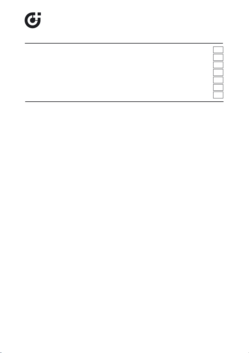
Le valvole termostatizzabili serie 455 possono essere utilizzate su impianti
a radiatori di tipologia sia ad anello monotubo che bitubo. Sono
predisposte per l’accoppiamento con comandi termostatici od
elettrotermici per effettuare la regolazione della temperatura ambiente in
modo automatico. Sono installabili sul radiatore nel solo attacco inferiore,
che viene utilizzato sia per l’entrata che per l’uscita del fluido.
The 455 series convertible valves can be used both on one-pipe and twopipe radiator systems. They are suitable for thermostatic control heads or
thermo-electric actuators to regulate automatically the ambient
temperature. They must be installed only at the radiator lower connection,
which is used both as medium inlet and medium outlet.
Die thermostatisierbaren Ventile der Serie 455 eignen sich für Ein- und
Zweirohr-Heizungsanlagen. Sie sind mit einem Thermostatkopf oder
einem elektrothermischen Stellantrieb für die automatische Regelung der
Raumtemperatur nachrüstbar. Die Installation ist nur auf dem unteren
Anschluss des Heizkörpers, der sowohl als Zu-, als auch als Abfluss für
den Wärmeträger dient, möglich.
Les robinets thermostatisables série 455 peuvent être utilisées sur des
installations dotées de radiateurs de type à boucle monotube et bitube.
Ils sont conçus pour être accouplés avec des têtes thermostatiques ou
électrothermiques pour régler automatiquement la température ambiante.
Ils doivent être installés uniquement sur le raccord inférieur du radiateur,
à savoir celui qui est utilisé pour l’arrivée et la sortie du fluide.
Las válvulas termostatizables serie 455 se pueden aplicar a los
radiadores de instalaciones monotubo o bitubo. Permiten el montaje de
mandos termostáticos o electrotérmicos para regular la temperatura
ambiente de modo automático. Se instalan en la conexión inferior del
radiador, que se utiliza para la entrada y la salida del líquido.
As válvulas termostatizáveis série 455 podem ser utilizadas em
instalações com radiadores de tipo monotubo ou bitubo.
Estão preparadas para o acoplamento com comandos termostáticos ou
electrotérmicos para efectuar a regulação da temperatura ambiente de
forma automática. Podem ser instalados no radiador apenas na ligação
inferior, que é utilizada seja para a entrada seja para a saída do fluido.
1
www.caleffi.com
CALEFFI
455 series
© Copyright 2008 Caleffi
Page 2
Technical
specifications
Materials: - body: brass EN 1982 CB753S, chrome plated
- headwork: brass EN 12164 CW614N
- obturator control stem: stainless steel
- spring: stainless steel
- hydraulic seals: EPDM
- control knob: ABS
- probe holder (deflector): POM
- probe: brass EN1249 CW508L
- lockshield: brass EN 12164 CW614N
Medium: water, glycol solutions
Max. percentage of glycol: 30%
Max. working pressure: 10 bar
Working temperature range: 5–100°C
Max. differential pressure (with thermostatic control head): 1 bar
Flow rate to radiator (for one-pipe version):
- with manual control knob: 50%
- with thermostatic control head (proportional range 2K): 30%
Threaded connections:
- radiator: 1/2”, 3/4”, 1” right, 1” left
- pipes: 23 p.1,5, centre distance 40 mm
Probe lenght: 300 mm
Probe diameter: - 1/2” e 3/4” 11 mm
- 1” 14 mm
Total length with thermostatic control head: 147 mm
Conversion from one-pipe to two-pipe mode and vice versa by means of 10 mm
Allen key
Product range
455400
1/2” 23 p.1,5
455500
3/4” 23 p.1,5
455600
1” right 23 p.1,5
455601
1” left 23 p.1,5
2
Pipe connectionRadiator connectionCode
De thermostatiseerbare ventielen van de serie 455 kunnen zowel op
éénpijps- als op tweepijpsradiatorsystemen toegepast worden. Ze kunnen
voorzien worden van thermostaatkoppen of elektrothermische bedieningen
voor het automatisch regelen van de omgevingstemperatuur . Ze mogen
uitsluitend geïnstalleerd worden op de onderste radiatoraansluiting, die
zowel aanvoer als retour is.
Page 3

Caratteristiche
idrauliche
Hydraulic
characteristics
Hydraulische
Merkmale
Caractéristiques
hydrauliques
Características
hidràulicas
Características
hidráulicas
Hydraulische
karakteristieken
3
4
3
·
·
·
·
·
·
2
Valvola serie 455, MONOTUBO: Kv complessivo con detentore incorporato
nel cannotto in posizione “tutto aperto”. Perdite di carico agli attacchi delle
tubazioni.
455 series valve, ONE-PIPE: total Kv with the lockshield, built-in in the
sleeve, in “fully open” position. Head losses at the pipe connections.
Ventil Serie 455, EINROHRIG: Kv-Gesamtwert mit eingebauter
Rücklaufverschraubung in der Stellung “ganz offen”. Druckverluste an den
Leitungsanschlüssen.
Robinet série 455, MONOTUBE : Kv total avec coude de réglage incorporé
dans le mécanisme en position “ouvert”. Pertes de charge sur les raccords
des conduits.
Válvula serie 455, MONOTUBO: Kv total con detentor incorporado en el
cilindro de la válvula en posición “todo abierto”. Pérdidas de carga en las
conexiones de los tubos.
Válvula série 455, MONOTUBO: Kv total com detentor incorporado no tubo
na posição “tudo aberto”. Perdas de carga nas ligações da tubagem.
Ventiel serie 455, EENPIJPS: kv met ingebouwd voetventiel volledig opend.
Drukverliezen bij de aansluitingen van de buis.
Set 1: manopola tutta chiusa, 100% della portata in by-pass.
Set 1: control knob fully closed, 100% of flow rate in by-pass.
Set 1: Regler ganz geschlossen, 100% der Durchflussmenge in bypass.
Set 1 : poignée fermée, 100% du débit en by-pass.
Posición 1: volante todo cerrado, 100% del caudal en bypass.
Set 1: manípulo todo fechado, 100% do caudal em by-pass.
Set 1: handwiel volledig dicht, debiet 100% via by-pass.
Kv
0,01
=145 l/h
Kv=1,45 m3/h
Set 2: comando termostatico al posto della manopola, banda proporzionale 2K,
30% di portata al radiatore, 70% in by-pass.
Set 2: thermostatic control head replacing the control knob, proportional range 2K,
30% of flow rate to the radiator, 70% in by-pass.
Set 2: Thermostatischer Regler an Stelle der Handregulierkappe, Proportionalbereich 2K,
30% der Durchflussmenge zum Heizkörper, 70% Bypass.
Set 2: tête thermostatique à la place de la poignée, bande proportionnelle 2K,
30% de débit au radiateur, 70% en by-pass.
Posición 2: mando termostático en lugar del volante, banda proporcional 2K,
30% de caudal al radiador, 70% en bypass.
Set 2: comando termostático no lugar do manípulo, banda proporcional 2K,
30% do caudal para o radiador, 70% em by-pass.
Set 2: thermostatische kop i.p.v. de handknop, proportionele band: 2K,
debiet: 30% naar radiator, 70% via by-pass.
Kv
0,01
=170 l/h
Kv=1,7 m3/h
Set 3: manopola tutta aperta, 50% di portata al radiatore, 50% in by-pass.
Set 3: control knob fully open, 50% of flow rate to the radiator, 50% in by-pass.
Set 3: Regler ganz offen, 50% der Durchflussmenge zum Heizkörper, 50% Bypass.
Set 3 : robinet ouvert, 50% de débit au radiateur, 50% en by-pass.
Posición 3: volante todo abierto, 50% de caudal al radiador, 50% en bypass.
Set 3: manípulo todo aberto, 50% do caudal para o radiador, 50% em bypass.
Set 3: handknop volledig open, debiet: 50% naar radiator, 50% via by-pass.
Kv
0,01
=200 l/h
Kv=2,0 m
3
/h
Page 4

4
4
3
·
·
·
·
·
·
2
Valvola serie 455, BITUBO: Kv complessivo con detentore incorporato nel
cannotto in posizione “tutto aperto”. Perdite di carico agli attacchi delle
tubazioni.
455 series valve, TWO-PIPE: total Kv with the lockshield, built-in in the
sleeve, in “fully open” position. Head losses at the pipe connections.
Ventile Serie 455, ZWEIROHRIG: Kv-Gesamtwert mit eingebauter
Rücklaufverschraubung in der Stellung “ganz offen”. Druckverluste an den
Leitungsanschlüssen.
Robinet série 455, BITUBE : Kv total avec coude de réglage incorporé dans
le mécanisme en position “ouvert”. Pertes de charge sur les raccords des
conduits.
Válvula serie 455, BITUBO: Kv total con detentor incorporado en el cilindro
de la válvula en posición “todo abierto”. Pérdidas de carga en las
conexiones de los tubos.
Válvula série 455, BITUBO: Kv total com detentor incorporado no tubo
na posição “tudo aberto”. Perdas de carga nas ligações da tubagem.
Ventiel serie 455, TWEEPIJPS: kv met ingebouwd voetventiel volledig
geopend. Drukverliezen bij de aansluitingen van de buis.
Set 1: comando termostatico al posto della manopola, banda proporzionale 2K,
100% di portata al radiatore. By-pass non attivo nella modalità bitubo.
Set 1: thermostatic control head replacing the tilted control knob, proportional range 2K,
100% of flow rate to the radiator. By-pass inactive (closed) in two-pipe configuration.
Set 1: thermostatischer Regler an Stelle der Handregulierkappe, Proportionalbereich 2K,
100% der Durchflussmenge zum Heizkörper. Bypass im Zweirohr-Modus nicht aktiv.
Set 1: tête thermostatique à la place de la poignée, bande proportionnelle 2K,
100% de débit au radiateur. By-pass non actif en version bitube.
Posición 1: mando termostático en lugar del volante, banda proporcional 2K,
100% de caudal al radiador. Bypass no disponible en la modalidad bitubo.
Set 1: comando termostático no lugar do manípulo, banda proporcional 2K,
100% de caudal para o radiador. By-pass não activo na modalidade bitubo.
Set 1: thermostatische kop i.p.v. de handknop, proportionele band: 2K, debiet:
100% naar radiator. By-pass niet in gebruik.
Kv
0,01
=55 l/h
Kv=0,55 m3/h
Set 2: manopola tutta aperta, 100% di portata al radiatore. By-pass non attivo nella
modalità bitubo.
Set 2: control knob fully open, 100% of flow rate to the radiator. By-pass inactive
(closed) in two-pipe configuration.
Set 2: Regler ganz offen, 100% der Durchflussmenge zum Heizkörper. Bypass im
Zweirohr-Modus nicht aktiv.
Set 2: robinet ouvert, 100% de débit au radiateur. By-pass non actif en version bitube.
Posición 2: volante todo abierto, 100% de caudal al radiador. Bypass no disponible en
la modalidad bitubo.
Set 2: manípulo todo aberto, 100% de caudal para o radiador. By-pass não activo na
modalidade bitubo.
Set 2: handknop volledig open, debiet: 100% naar radiator. By-pass niet in gebruik.
Kv
0,01
=110 l/h
Kv=1,1 m
3
/h
Page 5
5
Bilanciamento
Balancing
Abgleich
Équilibrage
Equilibrado
Balanceamento
Inregeling
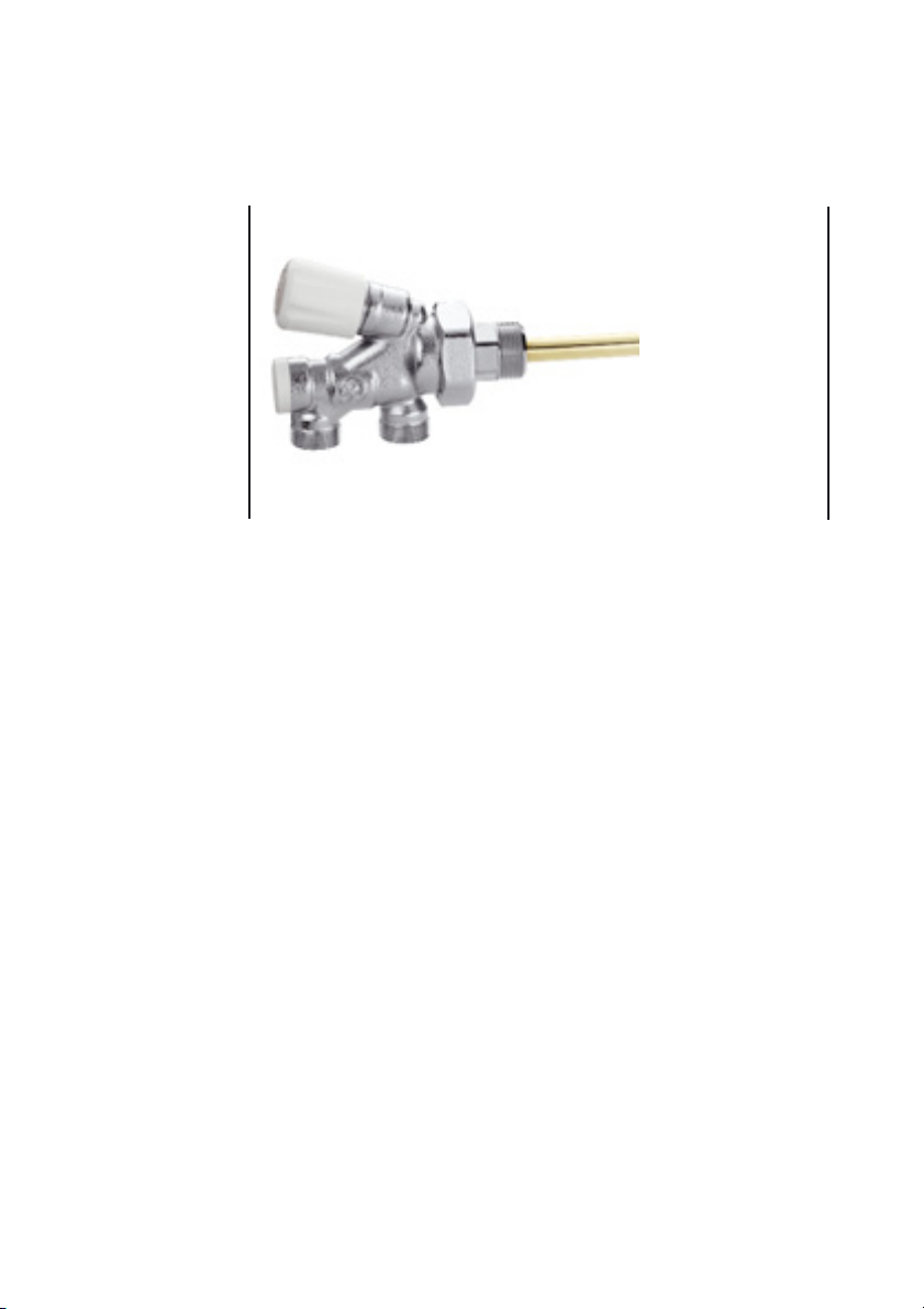
Valvola serie 455, BITUBO: variazione del Kv
complessivo con comando termostatico
durante il bilanciamento con detentore
incorporato nel cannotto orizzontale. Banda
proporzionale 2K. Perdite di carico agli
attacchi delle tubazioni.
455 series valve, TWO-PIPE: total Kv variation with a thermostatic control
head during the balancing by means of the lockshield, built-in in the
horizontal sleeve. Proportional range 2K. Head losses at the pipe
connections.
Ventil Serie 455, ZWEIROHRIG: Änderung des Kv-Gesamtwertes mit thermostatischem
Regler während des Abgleichs mit Rücklaufverschraubung. Proportionalbereich 2K.
Druckverluste an den Rohranschlüssen.
Robinet série 455, BITUBE : variation du Kv total avec tête thermostatique durant
l'équilibrage avec coude de réglage incorporé dans le mécanisme horizontal. Bande
proportionnelle 2K. Pertes de charge sur les raccords des conduits.
Válvula serie 455, BITUBO: variación del Kv total con mando termostático
durante el equilibrado con detentor incorporado en el cilindro horizontal.
Banda proporcional 2K. Pérdidas de carga en las conexiones de los tubos.
Válvula série 455, BITUBO: variação do Kv total com comando termostático
durante o balanceamento com detentor incorporado no mecanismo horizontal.
Banda proporcional 2K. Perdas de carga nas ligações da tubagem.
Ventiel serie 455, TWEEPIJPS: variatie van de totale kv tijdens de inregeling
van het voetventiel. Proportionele band: 2K. Drukverliezen bij de
aansluitingen van de buis.
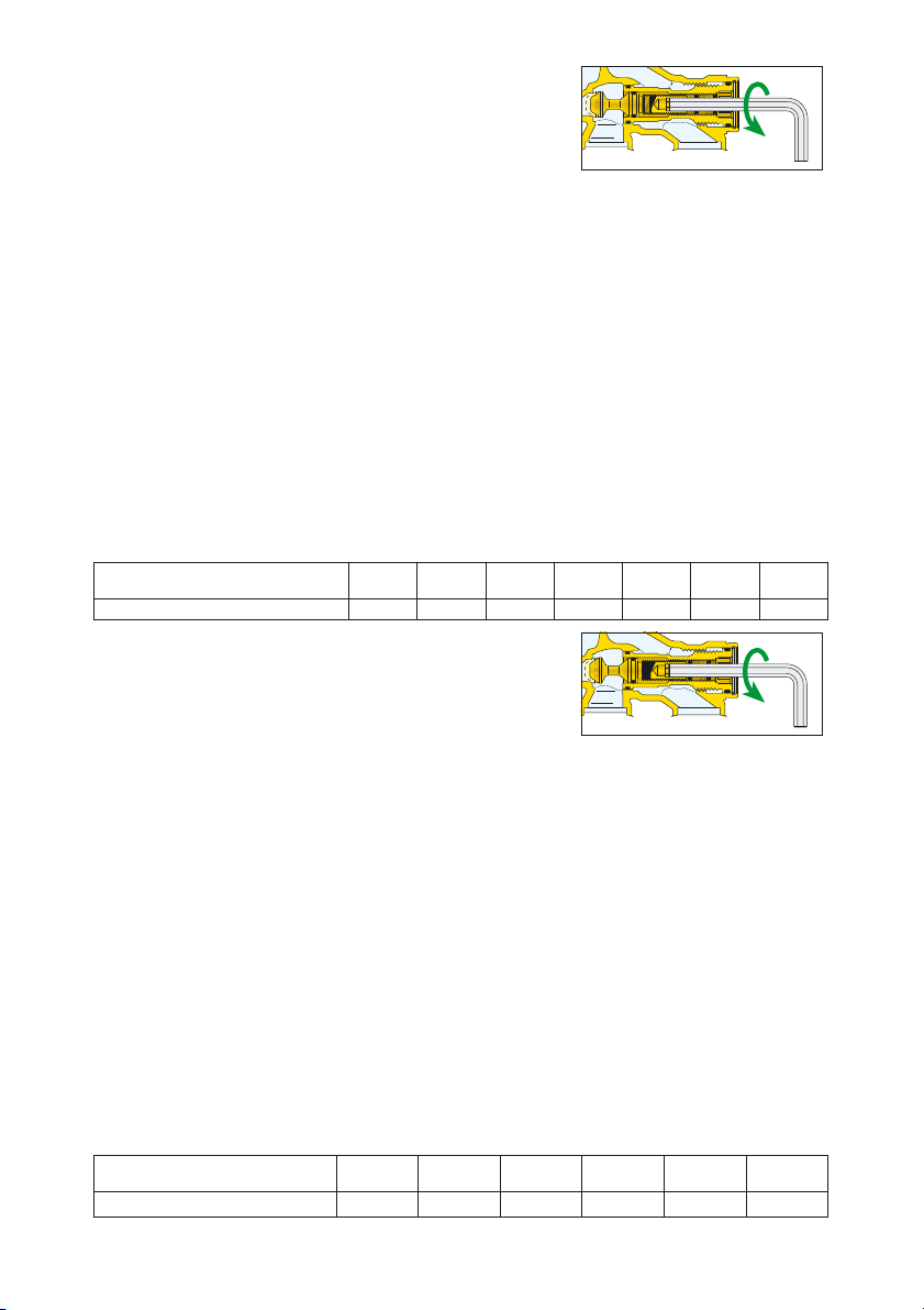
Valvola serie 455, BITUBO: variazione del
Kv complessivo con manopola manuale di
intercettazione tutta aperta durante il
bilanciamento mediante detentore
incorporato nel cannotto orizzontale.
Perdite di carico agli attacchi delle
tubazioni.
455 series valve, TWO-PIPE: total Kv variation with the manual control knob
fully open, during the balancing by means of the lockshield, built-in in the
horizontal sleeve. Head losses at the pipe connections.
Ventil Serie 455, ZWEIROHRIG: Änderung des Kv-Gesamtwertes mit ganz
geöffneter Absperrung beim Abgleich mit Rücklaufverschraubung. Druckverluste
an den Leitungsanschlüssen.
Robinet série 455, BITUBE : variation du Kv total avec tête manuelle d'arrêt
ouverte durant l'équilibrage avec coude de réglage incorporé dans le
mécanisme horizontal. Pertes de charge sur les raccords des conduits.
Válvula serie 455, BITUBO: variación del Kv total con volante manual de
corte todo abierto durante el equilibrado mediante detentor incorporado en
el cilindro horizontal. Pérdidas de carga en las conexiones de los tubos.
Válvula série 455, BITUBO: variação do Kv total com manípulo manual de
intercepção todo aberto durante o balanceamento através de detentor
incorporado no mecanismo horizontal. Perdas de carga nas ligações da
tubagem.
Ventiel serie 455, TWEEPIJPS: variatie van de totale kv met de handknop
volledig geopend tijdens de inregeling van het voetventiel. Drukverliezen bij
de aansluitingen van de buis.
N° giri detentore
Nr. of lockshield turns:
0,5 1 1,5 2 3
T.A.
F.O.
Kv (m3/h)
0,34 0,62 0,78 0,91 1,09 1,15
N° giri detentore
Nr. of lockshield turns:
0,5 1 1,5 2 2,5 3
T.A.
F. O.
Kv (m3/h)
0,31 0,47 0,55 0,57 0,58 0,61 0,62
Page 6

6
La valvola viene fornita predisposta per il funzionamento monotubo.
La valvola può essere montata con gli attacchi verso il muro o verso il
pavimento ma sempre con la sonda in orizzontale. L'allacciamento alle
tubazioni non ha un senso di entrata o di uscita obbligato ma nella versione
bitubo è consigliabile l'entrata nell'attacco più vicino al radiatore. Per
escludere il corpo scaldante occorre chiudere la manopola inclinata e, con
una chiave esagonale da 5 mm, l'otturatore (1).
La procedura di installazione è la seguente:
Fig. 1) La sonda è inserita nel portasonda e sporge della quantità necessaria
all’accoppiamento con il deflettore in plastica. Controllare che la sonda
vada correttamente a battuta nella sede di 2 mm del deflettore (2).
Questo garantisce una adeguata circolazione del fluido termovettore.
Fig. 2) Installare la valvola sui tubi di mandata e ritorno del fluido.
Fig. 3) Inserire il deflettore in plastica bianca sul corpo valvola.
Fig. 4) Inserire e fissare la sonda nel radiatore.
Fig. 5)
Allineare l’estremo della sonda al deflettore montato sul corpo valvola
prestando attenzione a non strisciare né il portasonda né la sonda contro
il deflettore in plastica per non danneggiarlo (fig. 5A), per non
compromettere la tenuta ed il corretto funzionamento della valvola. Per
eseguire questa operazione, occorre ruotare il radiatore, appoggiato sulle
staffe a muro, creando la giusta distanza tra il portasonda ed il deflettore.
Fig.6) Avvitare il bocchettone del portasonda al corpo valvola.
Durante l’installazione è necessario prestare attenzione a non danneggiare in
alcun modo anche la sonda stessa. Qualora questa venisse schiacciata, si
comprometterebbe il funzionamento della valvola alterando la portata inviata
al radiatore e, di conseguenza, non si raggiungerebbe una temperatura
adeguata nel corpo scaldante.
Installazione
Installation
Einbau
Installation
Instalación
Instalação
Installatie
1
5 mm
2
2
1
3
4
55A6
Page 7

7
The radiator valve is supplied for one-pipe system usage.
The valve can be installed with the connections facing the wall or pointing
downwards but always with the probe horizontal. The pipe connections are
interchangeable although for two-pipe systems it is suggested that the
connection nearest the radiator is used as the inlet (flow) connection. To
isolate the radiator, shut off the tilted control knob and, after removing the end
cap, shut off the regulation/isolating lockshield valve (1) using a 5 mm Allen key.
Here the installation procedure follows:
Fig. 1) The probe is fixed within the holder, leaning out enough to be correctly
coupled to the plastic deflector. When coupling, be sure that the probe
is fully deep inside the 2 mm seat of the deflector (2), to guarantee a
correct circulation of the thermal medium.
Fig. 2) Install the valve on both the flow and return pipe.
Fig. 3) Insert the white plastic deflector on the valve body.
Fig. 4) Insert and screw the probe inside the radiator.
Fig. 5) Align the probe end to the deflector, previously installed on the valve
body, paying attention to slide neither the probe holder nor the probe
against the deflector, to avoid any damage (fig. 5A). Otherwise, the
probe-deflector interface could be no more water-tight and the valve
could work incorrectly. For this operation, it is necessary to rotate the
radiator, hang on the wall brackets, creating the right distance
between the probe holder and the deflector.
Fig.6) Screw the probe holder’s union to the valve body.
During the installation it is necessary to avoid any damage to the probe itself.
If this were compressed, the valve function would be compromised thus
modifying the flow rate to the radiator and, as a consequence, it would be
impossible to reach an adequate temperature within the heating element.
Das Ventil wird für den Einrohrbetrieb eingestellt geliefert.
Das Ventil kann mit zur Mauer oder zum Boden gerichteten Anschlüssen
montiert werden, der Fühler muss immer waagrecht stehen. Beim Anschluss
an die Rohrleitungen ist KEINE Zu- bzw. Ablaufrichtung vorgegeben;
allerdings muss der Zulauf bei der Zweirohr-Ausführung der am Heizkörper
liegen de sein. Zum Schließen des Heizkörpers müssen das geneigte Ventil
und der Schieber (1) mit einem 5-mm-Sechskanteinsteckschlüssel abgesperrt
werden.
Installation:
Abb. 1) Das Tauchrohrhler sitzt in seiner Halterung und steht so weit heraus,
wie es für den Anschluss an das Zwischenstück aus Plastik
erforderlich ist. Sich vergewissern, dass das Tauchrohr richtig bis zum
Anschlag im 2 mm tiefen Sitz des Zwischenstückes aus Plastik sitzt. (2).
Nur so kann das die Wärme leitende Medium korrekt zirkulieren.
Abb. 2) Das Ventil auf dem Vor- und dem Rücklauf installieren.
Abb. 3) Das Zwischenstück aus weißem Plastik auf das Ventilgehäuse setzen.
Abb. 4) Das Tauchrohr in den Heizkörper einsetzen und befestigen.
Abb. 5) Das Ende des Tauchrohres auf das auf dem Ventilgehäuse montierte
Zwischenstück ausrichten; dabei darauf achten, dass weder die
Rohrhalterung noch das Rohr das Zwischenstück aus Plastik
beschädigen (Abb. 5A) und dadurch das Ventil undicht wird und nicht
mehr einwandfrei funktioniert. Dazu den auf den Halterungen an der
Wand sitzenden Heizkörper so drehen, dass der richtige Abstand
zwischen Fühlerhalterung und Zwischenstück geschaffen wird.
Abb.6) Den Stutzen der Tauchrohrhalterung an das Ventilgehäuse
anschrauben.
Page 8

8
La válvula se suministra preparada para el funcionamiento en monotubo.
La válvula se puede montar con las conexiones hacia la pared o hacia el
suelo, pero siempre con la sonda horizontal. La conexión a los tubos NO
tiene un sentido de entrada o salida obligatorio, pero en los sistemas
bitubo se aconseja hacer la entrada en la conexión más cercana al
radiador. Para excluir el emisor de calor hay que cerrar la válvula inclinada
y, con una llave hexagonal de 5 mm, el obturador (1).
El procedimiento de instalación es el siguiente:
Fig. 1) La sonda está introducida en el portasonda y sobresale en la
medida necesaria para acoplarse con el deflector de plástico. Al
realizar el acoplamiento, controlar que la sonda se inserte
completamente en el alojamiento de 2 mm del deflector (2). Esto
garantiza la circulación adecuada del fluido caloportador.
Fig. 2) Instalar la válvula en los tubos de ida y retorno del fluido.
Fig. 3) Introducir el deflector de plástico blanco en el cuerpo de la válvula.
Fig. 4) Insertar y fijar la sonda en el radiador.
Fig. 5) Alinear el extremo de la sonda con el deflector montado en el
cuerpo de la válvula. Tener cuidado de que el portasonda y la
sonda no rocen el deflector de plástico (fig. 5A), ya que éste podría
dañarse y comprometer la estanqueidad y el funcionamiento
correcto de la válvula. Para efectuar esta operación hay que girar
el radiador, apoyado en el soporte mural, a fin de crear el espacio
necesario entre el portasonda y el deflector.
Fig. 6) Enroscar la unión del portasonda al cuerpo de la válvula.
Durante la instalación, tener cuidado de no dañar la sonda. Si la sonda se
aplasta, la válvula no funciona correctamente y se altera el caudal enviado
al radiador, impidiendo obtener la temperatura esperada.
Le rebinet est livré prêt pour le fonctionnement en version monotube.
Il est possible de monter le robinet en tournant les raccords vers le mur ou vers
le sol, mais toujours avec la sonde en position horizontale. Le raccordement
aux conduits N'A PAS un sens d'entrée ou de sortie obligatoire mais, pour la
version bitube, il est conseillé de placer l'entrée sur le raccord le plus proche
du radiateur. Pour isoler le corps chauffant, fermer la vanne inclinée et prendre
une clé à six pans de 5 mm pour fermer l'obturateur (1).
Procéder à l'installation de la façon suivante :
Fig. 1) La sonde est installée dans son support et dépasse juste le nécessaire
pour être raccordée au déflecteur en plastique. S'assurer que la sonde
arrive au fond du logement de 2 mm du déflecteur (2). Ceci garantit la
bonne circulation du fluide caloporteur.
Fig. 2) Installer le robinet sur les tubes de départ et de retour du fluide.
Fig. 3) Installer le déflecteur en plastique blanc sur le corps de la vanne.
Fig. 4) Installer et fixer la sonde dans le radiateur.
Fig. 5) Aligner l’extrémité de la sonde avec le déflecteur monté sur le corps de
la vanne en ayant soin de ne frotter ni le support de la sonde ni la
sonde contre le déflecteur en plastique pour ne pas l'endommager
(fig. 5A) et ne pas compromettre son étanchéité et le fonctionnement
de la vanne. Pour effectuer cette opération, tourner le radiateur posé
sur les étriers au mur en calculant la bonne distance entre le support
de la sonde et le déflecteur.
Fig.6) Visser la goulotte du support sur la vanne.
Durant l’installation, prendre soin de ne pas endommager la sonde. Au cas où
elle serait écrasée, le débit au radiateur serait compromis et par conséquent
tout le fonctionnement de la sonde. Ceci empêcherait le corps chauffant
d'atteindre la température nécessaire.
Page 9

9
Het ventiel wordt geleverd voor gebruik in éénpijpssystemen.
Het ventiel kan gemonteerd worden met de aansluitingen naar de muur of
naar de vloer gericht, maar altijd met de voeler horizontaal. Bij
tweepijpssystemen dient de aanvoer te gebeuren via de aansluiting die
het dichtst bij de radiator ligt. Bij de andere systemen is dit niet verplicht.
Om de radiator af te sluiten draait men de handknop dicht en dient men
de klep af te sluiten met een zeskantsleutel van 5 mm (1).
Werkwijze bij installatie:
Afb. 1) De voeler bevindt zich in de dompelhuls en steekt iets uit, zodat hij
goed kan aansluiten op de kunststof straalbreker. Controleer of de
voeler perfect aansluit op de 2mm zitting van de straalbreker (2) om
een goede circulatie te garanderen.
Afb. 2) Installeer het ventiel op de aanvoer- en retourleiding.
Afb. 3) Breng de witte kunststof straalbreker aan op het ventiellichaam.
Afb. 4) Plaats de voeler in de radiator en zet hem vast.
Afb. 5) Lijn het uiteinde van de voeler uit met de straalbreker die reeds op
het ventiellichaam gemonteerd zit. Zorg ervoor dat de dompelhuls
en de voeler de kunststof straalbreker niet raken om schade (afb.
5A) te voorkomen en de waterdichtheid en goede werking van het
ventiel te garanderen. Om deze werkzaamheid te kunnen uitvoeren
dient men de radiator te draaien en de beugels zodanig op de
wand te monteren dat de afstand tussen dompelhuls en
straalbreker groot genoeg is.
Afb. 6) Draai de dompelhuls vast op het ventiellichaam.
Zorg ervoor dat de voeler niet beschadigd raakt tijdens de installatie.
Indien de voeler samengedrukt wordt, dan beïnvloedt dit de werking en wijzigt
het debiet naar de radiator met een te lage radiatortemperatuur als gevolg.
A válvula é fornecida pronta para o funcionamento monotubo.
A válvula é fornecida preparada para o funcionamento monotubo.
A válvula pode ser montada com as ligações na parede ou no chão, mas
sempre com a sonda na horizontal. A ligação à tubagem não tem um
sentido de entrada ou de saída obrigatório, mas na versão bitubo é
aconselhável a entrada na ligação mais próxima ao radiador.
Para seccionar o radiador, é necessário fechar a válvula inclinada e, com
uma chave hexagonal de 5 mm, o obturador (1).
O procedimento de instalação é o seguinte:
Fig. 1) A sonda é inserida no porta-sonda e sobra a quantidade necessária
para o acoplamento ao deflector em plástico. Controlar que a sonda
entre correctamente na sede de 2 mm do deflector (2). Isto garante
uma adequada circulação do fluido termovector.
Fig. 2) Instalar a válvula na tubagem de ida e de retorno do fluido.
Fig. 3) Inserir o deflector em plástico branco no corpo da válvula.
Fig. 4) Inserir e fixar a sonda no radiador.
Fig. 5) Alinhar a extremidade da sonda ao deflector montado no corpo da
válvula prestando atenção para não arrastar nem o porta-sonda nem
a sonda contra o deflector em plástico, para não o danificar (fig. 5A),
e para não comprometer a retenção, e o correcto funcionamento da
válvula. Para executar esta operação, é necessário rodar o radiador,
apoiado nos suportes de parede, criando a distância correcta entre
o porta-sonda e o deflector.
Fig.6) Aparafusar o casquilho do porta-sonda ao corpo da válvula.
Durante a instalação é necessário prestar atenção para não danificar de
forma alguma a própria sonda. Caso esta fique esmagada, pode
comprometer-se o funcionamento da válvula alterando o caudal enviado
para o radiador e, por conseguinte, não se alcançará uma temperatura
adequada no radiador.
Page 10

10
Trasformazione
da monotubo a
bitubo
Conversion
from one-pipe
to two-pipe
system
operation
Umstellung von
Einrohr- auf
Zweirohrsystem
Trasformation
de monotube
en bitube
Transformación
de monotubo a
bitubo
Transformação
de monotubo
para bitubo
Omschakelen
van
éénpijpsaansluit
ing naar
tweepijpsaanslu
iting
La valvola è fornita con il cannotto (3) in posizione avanzata (monotubo).
The radiator valve is provided with the sleeve (3) in forward position (for
one-pipe system application).
Das Ventil wird werksseitig mit der Voreinstellung in Stellung (3) geliefert
(Einrohrsystem).
Le robinet est livrée avec le mécanisme (3) en position avancée (utilisation
monotube).
La válvula es suministrada con el tubo (3) en posición adelantada
(monotubo).
A válvula é fornecida com o tubo (3) na posição avançada (monotubo).
Het ventiel wordt geleverd met de by-pass (3) open (éénpijpsaansluiting).
3
Page 11

Per trasformare la valvola per utilizzarla su impianti con distribuzione a due
tubi occorre togliere il cappuccio (4) e svitare il cannotto (3) con una
chiave esagonale da 10 mm fino a battuta.
For use on a two-pipe system, remove the end cap (4) and fully unscrew
the sleeve (3) using a 10 mm Allen key.
Für das Umstellen auf Zweirohrsystem muß die Schutzkappe (4)
abgenommen und die Voreistellung in Stellung (3) mit Hilfe eines
Imbusschlüssels (10 mm) bis zum Anschlag herausgedreht werden.
Pour la transformation et l'utilisation sur une installation bitube dévisser le
bouchon (4), dévisser le mécanisme (3) avec une clé six pans de 10
jusqu'à la butée.
Para las instalaciones con distribución a dos tubos, hay que quitar el
capuchón (4) y destornillar todo el tubo (3) con una llave exagonal de 10 mm.
Para transformar a válvula para a utilizar nas instalações com distribuição a
dois tubos, é necessário tirar a tampa (4) e desaparafusar o tubo (3) com
uma chave hexagonal de 10 mm, até ao batente.
Om het ventiel om te bouwen voor gebruik in tweepijpssystemen,
verwijdert u het kapje (4) en draait u met een zeskantsleutel van 10 mm de
by-pass (3) volledig los.
4
10 mm
3
11
Page 12

12
Le valvole serie 455 possono essere rese termostatiche applicando il
comando serie 200, 201 e 202 al posto della manopola manuale. Il
comando termostatico può essere utilizzato sia nel caso in cui la valvola
abbia gli attacchi rivolti verso il muro sia verso il pavimento. Il sensore
incorporato nel comando termostatico è sufficientemente distante dal
corpo valvola ed effettua una lettura corretta della temperatura ambiente
senza essere influenzato dal calore irradiato dal corpo valvola stesso.
The 455 series valves can be converted to thermostatic valves applying
the thermostatic control heads 200, 201 and 202 series instead of the
manual control knob. The thermostatic control head can be used both with
the pipe connections pointing the wall and pointing the floor. The built-in
sensor of the control head is far enough from the valve body and is able to
perform a correct ambient temperature reading, without being influenced
by the heat radiated by the valve body itself.
Die Ventile der Serie 455 können durch Anbringen des Thermostatkopfes
der Serie 200, 201 und 202 an Stelle des manuellen Handrads auch zur
Raumtemperaturmessung eingesetzt werden. Der thermostatische Regler
kann sowohl mit zur Wand als auch zum Boden gerichteten
Ventilanschlüssen benutzt werden. Der in den thermostatischen Regler
eingebaute Temperaturfühler ist so weit vom Ventilgehäuse entfernt, dass
er die korrekte Raumtemperatur feststellen kann, ohne durch die vom
Gehäuse ausgestrahlte Wärme beeinflusst zu werden.
Les robinet série 455 peuvent devenir thermostatiques en installant la tête
série 200, 201 et 202 à la place de la poignée manuelle. La tête
thermostatique peut être utilisée aussi bien si les raccords du robinet sont
tournés vers le mur que s'ils sont tournés vers le sol. Le capteur incorporé
dans la tête thermostatique est suffisamment distant du corps du robinet et
effectue une lecture correcte de la température ambiante sans être influencé
par la chaleur que dégage le corps du robinet.
Las válvulas serie 455 se pueden convertir en termostáticas aplicando el
mando serie 200, 201 y 202 en lugar del volante manual. El mando
termostático se puede utilizar cuando la válvula tiene las conexiones hacia
la pared o hacia el suelo. El sensor incorporado en el mando termostático
está lo suficientemente alejado del cuerpo de la válvula para que la
lectura de la temperatura ambiente no se vea influenciada por el calor que
irradia la válvula.
As válvulas série 455 podem-se tornar termostáticas aplicando o comando
série 200, 201 e 202 no lugar do manípulo manual. O comando termostático
pode ser utilizado quer no caso em que a válvula tenha as ligações na
parede, quer estejam no chão. O sensor incorporado no comando
termostático é suficientemente distante do corpo da válvula, e efectua uma
leitura correcta da temperatura ambiente sem ser influenciado pelo calor
irradiado pelo próprio corpo da válvula.
Ventielen van de serie 455 kunnen thermostatisch bediend worden door de
handknop te vervangen door een thermostatische kop van de serie 200, 201
of 202. De thermostatische kop kan zowel toegepast worden als de
aansluitingen naar de vloer gericht zijn, als dat ze naar de muur gericht zijn.
De in de thermostaatkop ingebouwde voeler is ver genoeg van het
ventiellichaam verwijderd en meet de omgevingstemperatuur correct,
zonder dat hij door warmte van het ventiellichaam beïnvloed wordt.
Trasformazione
in valvola
termostatica
Conversion
from manual to
thermostatic
valve
Umrüstung auf
Thermostatventil
Montage d'une
tête
thermostatique
Transformación
en válvula
termostática
Transformação
em válvula
termostática
Thermostatische
bediening
Page 13

Le valvole devono essere installate da un installatore qualificato in accordo
con i regolamenti nazionali e/o i relativi requisiti locali.
Se le valvole non sono installate, messe in servizio e mantenute correttamente
secondo le istruzioni contenute in questo manuale, allora possono non
funzionare correttamente e possono porre l’utente in pericolo.
Assicurarsi che tutta la raccorderia di collegamento sia a tenuta idraulica.
Nella realizzazione delle connessioni idrauliche, prestare attenzione a non
sovrasollecitare meccanicamente il corpo valvola. Nel tempo si possono
produrre rotture con perdite idrauliche a danno di cose e/o persone.
Temperature dell’acqua superiori a 50°C possono provocare gravi ustioni.
Durante l’installazione, messa in servizio e manutenzione delle valvole,
adottare gli accorgimenti necessari affinché tali temperature non arrechino
pericolo per le persone.
Lasciare il presente manuale ad uso e servizio dell’utente
The valves must be installed by a licensed plumber in accordance with
national regulations and/or relevant local requirements.
If the valves are not installed, commissioned and maintained properly in
accordance with the instructions contained in this manual, they may not
operate correctly, and may cause damage to objects and/or people.
Make sure that all the connections are water-tight.
When making the water connections, take care not to over-tighten the
threaded connections. Otherwise, in time, failure could arise with water loss
causing damage to objects and/or people
Water temperatures in excess of 50°C can cause serious scalding.
During the installation, commissioning and maintenance of valves, all
necessary steps should be taken to ensure that water temperature do not
cause danger to people.
Leave this manual at the service of users for their use
Die Ventile müssen von einem qualifizierten Installateur unter Befolgung der
einschlägigen nationalen und/oder örtlichen Vorschriften eingebaut werden.
Falls die Ventile nicht wie in dieser Anleitung beschrieben korrekt installiert, in
Betrieb genommen und gewartet werden, können sie nicht einwandfrei
funktionieren und eine Gefahr für den Benutzer darstellen.
Die Dichtheit sämtlicher Anschlussverschraubungen überprüfen.
Bei der Ausführung der hydraulischen Anschlüsse ist darauf zu achten, dass
das Ventilgehäuse nicht mechanisch überbeansprucht wird. Im Lauf der Zeit
können Beschädigungen mit Leckverlusten und daraus resultierenden
Sach- und/oder Personenschäden auftreten.
Wassertemperaturen über 50°C können zu schweren Verbrühungen führen.
Während Installation, Inbetriebnahme und Wartung der Ventile sind die
notwendigen Vorkehrungen zu treffen, damit diese Temperaturen keine
Personen gefährden können.
Die vorliegende Produktanleitung ist dem Benutzer zu übergeben
Sicurezza
Safety
Sicherheit
Sécurité
Seguridad
Segurança
Veiligheid
13
Page 14

14
Les robinets doivent être installés par un installateur qualifié
conformément aux règlements nationaux et/ou aux conditions locales. Si
les robinets ne sont pas installés, mis en service et entretenus
correctement selon les instructions fournies dans ce manuel, ils risquent
de ne pas fonctionner correctement et de mettre l'utilisateur en danger.
S'assurer que tous les raccordements sont étanches.
Lors des raccordements hydrauliques, ne pas soumettre le robinet à des
efforts mécaniques inutiles. À la longue, ils peuvent se casser et
provoquer des fuites, avec risques de dommages physiques et matériels.
Au-delà de 50°C, l'eau risque de provoquer des brûlures.
Durant l’installation, la mise en service et l'entretien des robinets, adopter
les mesures nécessaires pour que la température ne provoque aucun
accident.
Laissez ce manuel à la disposition de l’utilisateur
Las válvulas deben ser montadas por un instalador cualificado y de
conformidad con las normas nacionales y locales. Si la instalación, la
puesta en servicio y el mantenimiento no se realizan de acuerdo con lo
indicado en este manual, las válvulas pueden no funcionar correctamente
y poner al usuario en peligro.
Controlar que todos los racores sean perfectamente estancos.
Al realizar el conexionado hidráulico, tener cuidado de no forzar
mecánicamente el cuerpo de la válvula. Con el tiempo podrían verificarse
pérdidas de agua con los consiguientes daños materiales o personales.
El agua a más de 50 °C puede causar quemaduras graves.
Durante la instalación, la puesta en servicio y el mantenimiento de las
válvulas, tomar las precauciones necesarias para que el agua caliente no
suponga ningún peligro.
Guarde el presente manual de uso y servicio al alcance del usario
As válvulas devem ser instaladas por um técnico qualificado de acordo
com as normas nacionais e/ou os respectivos requisitos locais.
Se as válvulas não forem instaladas, colocadas em funcionamento e
mantidas correctamente segundo as instruções contidas neste manual,
poderão não funcionar correctamente e colocar o utilizador em perigo.
É necessário certificar-se que todos os adaptadores de ligação tenham
vedação hidráulica.
Ao efectuar-se as ligações hidráulicas, ter em atenção para não forçar
mecanicamente o corpo da válvula.
Com o tempo, poderão ocorrer rupturas com perdas de água que podem
causar danos materiais e/ou pessoais.
Temperaturas da água superiores a 50°C podem provocar queimaduras
graves. Durante a instalação, a colocação em funcionamento e a
manutenção das válvulas, devem adoptar-se as precauções necessárias
para que tais temperaturas não coloquem as pessoas em perigo.
Este manual deve ficar à disposição do utilizador
Page 15

De ventielen moeten gemonteerd worden door een gekwalificeerde
installateur, in overeenstemming met de nationale wetgeving en/of
plaatselijke voorschriften. Indien de ventielen niet correct volgens de
instructies in deze handleiding geïnstalleerd, inbedrijfgesteld en
onderhouden worden, is het mogelijk dat ze niet goed werken en dat ze
de gebruiker in gevaar brengen.
Zorg ervoor dat alle aansluitingen waterdicht zijn. Let er bij het tot stand
brengen van de hydraulische aansluitingen op dat het ventiellichaam niet
mechanisch wordt overbelast. Dit om na verloop van tijd waterverlies met
schade aan zaken en/of letsel van personen te voorkomen.
Watertemperaturen van boven de 50°C kunnen ernstige brandwonden
veroorzaken.
Neem tijdens de installatie, de inbedrijfstelling en het onderhoud de
nodige maatregelen, zodat dergelijke temperaturen geen gevaar voor
personen opleveren.
Laat deze handleiding ter beschikking van de gebruiker
15
Page 16

16
 Loading...