

Page 1
www.cal effi .com
Valvola di sicurezza combinata
temperatura e pressione
Temperature and pressure relief
valve
Soupape de sécurité Température et
Pression
©
Copyright 2012 Caleffi
Generalità/General/Généralité
Le valvol e di sicurezz a combina ta temper atura e
pressione sono costruite da Caleffi S.p.A. nel rispetto dei
requisiti essenziali di sicurezza dettati dalla direttiva
P.E.D. del Parlamento Europeo e del Consiglio dell’Unione
Europea, per il riavvicinamento degli stati membri in
materia di attrezzature a pressione.
Le istruzioni di seguito forn ite sono realizzate in
conformità e con lo scopo di cui all’articolo 3.4–allegato 1
della direttiva P.E.D. ed accompagnano i prodotti durante
l’immissione nel mercato.
Temperature and pressure relief valves are made by
Caleffi S.p.A. in compliance with the essential safety
requirements laid down by Directiv e P.E.D. of the
European Parliament and the Council of the European
Union for har monisation of member States with regard to
pressurised equipment.
The instructions given in this leaflet are supplied in
compliance with the scope of article 3.4 – item 1 of
Directive P.E.D. and accompany each product supplied
to the market.
Les soupapes de sécurité thermique sont construites par
CaleffiS.p.A. dans le respect des exigences essentielle
de sécurité de la directive 97/23/CE du Parlement
Européen et du Conseil de l'Union Européenne, pour le
rapprochement des états membres en matière
d'appareils sous pression.
38594.02
I
GB
F
Series 309
Funzione ed impiego/Function and use/
Fonction et utilisation
La valvol a di sicurezz a combina ta temper atura e
pressione (TP) controlla e limita la temperatura e la
pressione dell’acqua calda contenuta in un accumulo
sanita rio ed e vita che in q uest’u ltimo si possan o
raggiu ngere temperature superiori ai 100°C, c on
formazione di vapore.
Al raggiungimento dei valori di taratura, la valvola scarica
in atmosfera una quantità d’acqua sufficiente a far sì che
temper atura e pressione r ientrino nei limiti di
funzionamento dell’impianto.
Questa particolare serie di valvole è certificata come
rispondente ai requisiti di prestazione della norma
europea EN 1490 (per tarature 4 - 7 - 10 bar).
The temperature and pressure relief valve (TP) controls
and limits the temperature and pressure of the hot water
contained in a domestic storage heater and prevents it
from being able to reach temperatures of over 100°C, with
the formation of steam.
On reaching the settings, the valve discharges a sufficient
amount of w ater into the atm osphere so t hat th e
temperature and pressure return within the system's
operating limits.
This particular series of valves is certified as conforming
to the performance requirements of the E uropean
standard EN 1490 (for settings of 4 - 7 - 10 bar).
1
Page 2
La soupape de sécurité TP contrôle et limite la température et
la pression du ballon d'eau chaude sanitaire.
Elle évite que la température de l'eau ne dépasse 100°C et
empêche donc la formation de vapeur.
Lorsque la valeur de tarage est atteinte, la soupape évacue
une quantité d’eau suffisante pour que la température et
la pression reviennent aux con ditions nor males de
fonctionnement de l’installation.
Cette série spéciale de soupapes est certifiée conforme à
la norme européenne EN 1490 (pour tarages 4 - 7 - 10 bar).
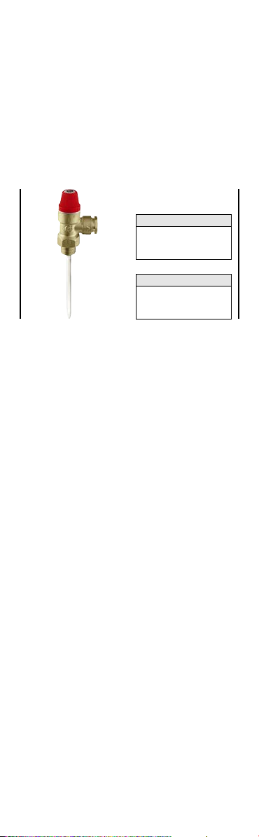
Gamma prodotti/Product Range/Gamme de produit
Probe L = 200 mm
1/2” x Ø 15 mm
3094 .5
309547 3/4” x Ø 15 mm
3095 .5 3/4” x Ø 22 mm
Probe L = 100 mm
1/2” x Ø 15 mm
3094 .0
309542 3/4” x Ø 15 mm
3095 .0 3/4” x Ø 22 mm
Caratteristiche tecniche/ Technical characteristics
Caractéristiques techniques
Materiali
Corpo: lega antidezincificazione CR
Asta: ottone UNI EN 12164 CW614N
Otturatore e membrana: EPDM
Molla: acciaio UNI EN 10270-1 SH
Manopola comando:
Prestazioni
Pressione nominale: PN 10
Potenzialità di scarico: - 1/2” e 3/4” Ø 15; 10 kW
Fluido d’impiego: acqua
Categoria PED: IV
Tarature: - temperatura: 90°C
- pressione: 3 - 4 - 6 - 7 - 10 bar
UNI EN 12165 CW602N
PA6G30
- 3/4” Ø 22; 25 kW
Materials
Body: antidezincification resistent alloy CR
Spindle: brass EN 12164 CW614N
Obturator and diaphragm: EPDM
Spring: steel EN 10270-1 SH
Control knob: PA6G30
Performance
Nominal pressure: PN 10
Discharge rating: - 1/2” and 3/4” Ø 15; 10 kW
Medium: Water
PED Category: IV
Setting: - temperature: 90°C
Matériaux
Corps: alliage anti-dézincification CR
Axe: laiton, EN 12164 CW614N
Obturateur et membrane : EPDM
Ressort: acier, EN 10270-1 SH
Poignée : PA6GF
Performances
Pression nominale: PN 10
Puissance évacuée: - 1/2” and 3/4” Ø 15; 10 kW
Fluide admissible: Eau
Catégorie PED: IV
Tarage: - température: 90°C
- 3/4ӯ 22; 25 kW
- pressure: 3 - 4 - 6 - 7 - 10 bar
- 3/4ӯ 22; 25 kW
- pression: 3 - 4 - 6 - 7 - 10 bar
EN 12165 CW602N
EN 12165 CW602N
2
Page 3

Taratura di fabbrica/Factory Setting/Tarage d'usine
La taratura delle valvole di sicurezza combinate TP si
effettua presso il fabbricant e. E’ vie tato qualunque
intervento atto ad alterare tali valori di pressione e
temperatura.
The setting of these TP safety valves is carried out by the
manufacturer. It is forbidden to interfere with or alter this
temperature and pressure value in any way.
Le tarage de la soupape de sécurité est effectué en
usine. Toute intervention pour modifier la valeur de
tarage est interdite et annule la garantie.
Installazione/Installation/Installation
Prima d ell’installazione di una valvola di s icurezza
combinate TP è necessario che ne sia eseguito un
corretto dimensionamento da parte di personale tecnico
special izzato, secondo la normat iva vige nte per le
specifiche applicazioni. E’ vietato farne un utilizzo diverso
rispetto alla sua destinazione d’uso.
L’installazione delle valvole di sicurezza combinate TP
deve essere eseguita da parte di personale tecnico
qualificato secondo la normativa vigente.
La valvola di sicurezza combinate TP deve essere
installata rispettando il senso di flusso indicato dalla
freccia riportata sul corpo valvola.
Before installing a TP relief valve, correct sizing must be
carrie d out by specialist t echnical person nel in
accordance with the current legislation governing specific
applications. It shall not be used other than for its stated
purpose.
TP relief valves must be installed by competent technical
personnel qualified in accordance with current legislation.
The TP relief valve must be installed in line with the flow
direction indicated by the arrow on the valve body.
Avant l'installation d'une soupape de sécurité TP, il est
nécessaire qu'elle soit correctement dimensionnée par un
technicien spécialisé, selon la réglementation en vigueur.
Il est interdit de l’utiliser dans un but différent de celui
pour lequel elle a été conçue.
L’installation des soupapes de sécurité TP est réservée à
un technicien qualifié, conformément à la norme en
vigueur.Installer la soupape de sécurité TP en respectant
le sens du flux indiqué par la flèche.
Montaggio/Fitting/Montage
Impianto idrosanitario
Le valvole di sicurezza combinate TP devono essere
installate sulla sommità dell’accumulo di acqua calda
avendo cura che la sonda di tem peratu ra sia
correttamente immersa nel serbatoio.
Avere cura che non ci sia inte rposizione di alcu n
dispositivo di intercettazione tra la valvola e l’accumulo.
Le valvole di sicurezza combinate TP possono essere
montat e in posizio ne vertical e od orizzon tale, non
capovolte.
In questo modo si evita che il deposito di impurità ne
pregiudichi il corretto funzionamento.
Domestic Hot Water System
TP relief valves must be installed on the top of the hot
water storage, making sure that the temperature probe is
correctly immersed in the tank.
Take care not to fit any shut-off devices between the valve
and the storage cylinder.
These TP relief valve s can be fitte d ve rtically o r
horizontally, but not upside down. This prevents deposits
of impurities from affecting correct functioning.
3
Page 4

HOT WATER
STORAGE
ACCUMULO
ACQUA
CALDA
BALLON
D'EAU
CHAUDE
HOT WATER
STORAGE
ACCUMULO
ACQUA
CALDA
BALLON
D'EAU
CHAUDE
HOT WATER
STORAGE
ACCUMULO
ACQUA
CALDA
BALLON
D'EAU
CHAUDE
HOT WATER
STORAGE
ACCUMULO
ACQUA
CALDA
BALLON
D'EAU
CHAUDE
Installazioni corrette/Correct installation
Montages correct
Installazioni errata/Incorrect installation
Montages incorrect
Installation d'eau chaude sanitaire
Installer les soupapes de sécurité TP sur le point haut du
ballon d'eau chaude en s’assurant que la sonde de
température est bien immergée.
S’assurer qu’aucun dispositif d’arrêt ne s’interpose entre
la soupape et le ballon d'eau chaude.
Les soupapes de sécurité TP peuvent être montées en
position verticale ou horizontale, mais ne doivent pas être
installées tête-bêche. On évite ainsi le dépôt d'impuretés
qui pourraient compromettre leur bon fonctionnement.
4
Page 5

Convogliamento scarico/Discharge Pipework/
SOLAR
STORAGE
ACCUMULO
SOLARE
CHAUFFE-EAU
SOLAIRE
Installazioni corrette/Correct installation
Montages correct
Installazioni errata/Incorrect installation
Montages incorrect
SOLAR
STORAGE
ACCUMULO
SOLARE
CHAUFFE-EAU
SOLAIRE
Évacuation
Poichè generalmente l’acqua scaricata dalle valvole di
sicurezza
combinate
provvedere al convogliamento dello scarico come segue, al
fine di evitare danni alle persone.
L’acqua di scarico deve essere convogliata in un tubo
verti cale at traver so un im buto op portun amente
distan ziato dal punto di scarico con prese d’aria
antiriflusso. Tale tubo di convogliamento deve avere le
seguenti caratteristiche:
- non deve distare più di 50 cm dallo scarico della
valvola stessa e deve essere posizionato nello stesso
locale dell’accumulo o in un locale chiuso.
- deve avere uno sviluppo verticale non minore di 30 cm
prima di proseguire con una pendenza che favorisca
comunque il deflusso dell’acqua.
- il diametro del tubo deve essere almeno di una misura
più grande della misura nominale dello scarico della
valvola
- deve terminare in un luogo sicuro dove, nel punto in cui
l’acqua viene scaricata e nelle vicinanze, non ci sia
alcun pericolo per le persone.
Since the water discharged by TP relief valv es is
generally close to 100°C, it is important to make sure that
the discharge pipework is made as follows in order to
prevent injury to people.
The discharge water must be conveyed in a vertical pipe
through a tundish at a suitable distance from the point of
discharge with an air gap. This pipework must have the
following characteristics:
- It must be no further than 50 cm from the valve outlet
and must be located in the same room as the storage
or in a closed room.
- Its vertical length must be no less than 30 cm before
continuing at an angle that anyhow aids the flow of water.
- The pipe diameter must be at least one size greater
than the nominal size of the valve outlet
- It must end in a safe place where, at the point where the
water is discharged and nearby, there is no danger
for people.
TP è prossima ai 100°C, è importante
5
Page 6

Max. 50 cm
Min. 30 cm
Valvola di sicurezza combinata TP
TP relief valve
Soupape de sécurité
Prese d’aria antiriflusso
Air gap
Entonnoir avec évent
Tubo di scarico
Discharge pipe
Conduit de décharge
Muro
Wall
Mur
Sifone
Siphon
Siphon
a
aa
a
a
1
2
3
5
1
4
2
3
4
5
HOT WATER
STORAGE
ACCUMULO
ACQUA
CALDA
BALLON
D'EAU
CHAUDE
Comme l'eau évacuée par la soupape est en général
proche de 100°C, il est important de s'assurer que le
circuit d'évacuation est correctement installé, comme
indiqué ci-dessous, afin d'éviter tout risque de brûlures.
L'eau doit être évacuée par un tube vertical à travers un
siphon situé à une distance suffisante de l'entonnoir avec
évent. Ce tuyau doit avoir les caractéristiques suivantes :
-Il ne doit pas être situé à plus de 50 cm de la sortie de
la soupape, et doit être dans le local même du ballon ou
dans un local fermé.
-Sa longueur minimum verticale ne doit pas être inférieure
à 30 cm avant de poursuivre avec une pente permettant
une bonne évacuation.
-Son diamètre doit être supérieur d'au moins une taille au
diamètre de sortie de la soupape.
-Il doit finir dans un endroit où il n'existe aucun risque
pour les personnes.
6
Page 7

Sicurezza
Le valvole di sicurezza combinate TP
installate da un installatore qualificato in accordo con i
regolamenti nazionali e/o i relativi requisiti locali.
Se le valvole di sicurezza combinate TP non sono
installate, messe in servizio e manutenute correttamente
secondo le istruzioni contenute in questo manuale, allora
possono non funzionare correttamente e possono porre
l’utente in pericolo.
Assicurarsi che tutta la raccorderia di collegamento sia a
tenuta idraulica.
Nella realizzazione delle connessioni idrauliche, prestare
attenzione a non sovrasollecitare meccanicamente la
filettatura del corpo valvola. Nel tempo si possono
produrre rotture con perdite idrauliche a danno di cose
e/o persone.
Temperature de ll’acq ua superio ri a 50°C possono
provocare gravi ustioni. Durante la installazione, messa in
serviz io e manutenzione delle valvo le di sicurezza
combin ate TP, ad ottare gli accorgimenti necessari
affinché tali temperature non arrechino pericolo per le
persone.
Lasciare il presente manuale ad uso
e servizio dell’utente
Safety
The
TP relief valves
in accordance with national regulations and/or relevant local
requirements.
If these TP relief valves are not installed, commissioned
and maintained correctly according to the instructions
contained in this leaflet, then they may not function
correctly and could put the user in danger.
Ensure that all connections are water-tight.
When making hydraulic connections, ensure that the
thread of the valve body is not mechanically overstressed.
Over time, breakages could occur, causing water leaks
which could be harmful to property and/or individuals.
Water temperatures in excess of 50°C can cause serious
scalding. During the installation, commissioning and
maintenance of these TP relief valves, all necessary steps
should be taken to ensure that such temperatures do not
cause danger to people.
must be installed by a licensed plumber
devono essere
Leave this instruction leaflet with the User.
7
Page 8

Attention
L’installation des soupape de sûreté thermique doit être
effectuée par des techniciens qualifiés sur la base des
indica tions f ournies par le présent manuel et
conformément aux normes en vigueur.
Si les soupapes ne sont pas correctement installées,
mises en fonction et entretenues conformément aux
instructions fournies dans ce manuel,elles peuvent ne
pas fonctionner correctement et mettre l'utilisateur en
danger.
S'assurer que tous les raccordements sont étanches
Dans la réalisation des connections hydrauliques, prêter
attention à ne pas serrer de façon excessive les raccords
sur la soupape Cela pourrait provoquer avec le temps
des ruptures et donc des fuites.
Au-delà de 50°C, l'eau risque de provoquer des brûlures.
Lors de l'installation, de la mise en fonction et de
l'entretien des soupapes de sûreté thermique, adopter les
mesures nécessaires pour que ces températures ne
mettent pas les personnes en danger.
Laissez ce manuel à la disposition de l’utilisateur
8
 Loading...