

Page 1
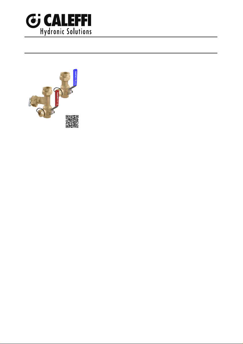
Tankless Water Heater Service Valve Kit
H0012145.01
www.caleffi.com
© Copyright 2023 Caleffi
Function
The 290 Series tankless water heater service valve kit connects directly
to the standard ¾” MNPT nipples on the heater to facilitate isolating,
flushing and servicing the water heater. The union connections make
installation simple and quick. The kit includes one blue-handled cold
water inlet full-port positive-shutoff 3-way ball valve, one red-handled
hot water outlet full-port 3-way positive-shutoff ball valve, and a
pressure relief valve in code KIT290503A, set to 150 psi, which
field-mounts to a side port on the hot water outlet ball valve. The
¾” garden hose capped connections are for hose hookups to flush
the heater.
Product range
KIT290503A* Tankless water heater kit including service valves with pressure relief valve............
size: ¾”
*Service valves in the kit are certified to section 1417(d) of the Safe Drinking Water Act, The lead content requirements of Section 116875
of the California Health & Safety Code and NSF/ANSI/CAN 372 . Listed by IAPMO R&T File Number K-14799.
Technical Characteristics
Materials:
Body, tailpiece: Low lead brass CW510L-DW
Ball: Chrome plated brass CW511L-DW
Seat: PTFE
Gasket: PTFE G300
Shaft, union nut: brass CW 617N-DW
O-ring seals: HNBR 70 Sh
Union male x female reducing adapter: Low lead brass CW724R-M
Union o-ring seals: peroxide-cured EPDM 70 Sh
290 Series
Performance:
Suitable fluids: Water
Cold working pressure (CWP): 600 psi (40 bar) up to 100 °F (40 °C)
Hot working pressure (HWP): 400 psi (27 bar) up to 230 °F (110 °C)
Working temperature range: -4 to 230 °F (-20 to 110 °C)
Seat leakage, 100% tested: 0%
Connections:
Tankless water heater cold inlet and hot outlet NPT male nipples: ¾” NPT female union
Flushing and servicing connections: ¾” capped garden hose
Hot water ball valve relief valve access port: ¾” NPT female
Pressure relief valve discharge port: ¾” NPT female
1
Page 2

SAFETY INSTRUCTION/
This safety alert symbol will be used in this manual to draw attention to safety related instructions. When used,
the safety alert symbol means ATTENTION! BECOME ALERT! YOUR SAFETY IS INVOLVED! FAILURE
TO FOLLOW THESE INSTRUCTIONS MAY RESULT IN A SAFETY HAZARD.
Ce symbole d’avertissement servira dans ce manuel à attirer l’attention sur la sécurité concernant instructions.
Lorsqu’il est utilisé, ce symbole signifie. ATTENTION! DEVENEZ ALERTE ! VOTRE SÉCURITÉ EST EN
JEU ! NE PAS SUIVRE CES INSTRUCTIONS PEUT PROVOQUER UN RISQUE DE SECURITE.
WARNING: This product can expose you to chemicals including lead, which
is known to the State of California to cause cancer and birth defects or other
reproductive harm. For more information go to www.P65Warning.ca.gov.
AVERTISSEMENT: Ce produit peut vous exposer à des produits chimiques
comme le plomb, qui est connu dans l’État de Californie pour causer le cancer,
dommages à la naissance ou autre. Pour plus d’informations rendez-vous www.
P65Warnings.ca.gov.
CAUTION: Caleffi shall not be liable for damages resulting from stress corrosion,
misapplication or misuse of it’s products.
AVERTISSEMENT: Caleffi ne sera pas responsable des dommages résultant
de la corrosion sous tension, d’une mauvaise application ou d’une mauvaise
utilisation de ses produits.
CAUTION: All work must be performed by qualified personnel trained in the
proper application, installation, and maintenance of systems in accordance with
all applicable codes and ordinances.
AVERTISSEMENT: Tous les travaux doivent être effectués par du personnel
qualifié formé à la bonne application, installation et maintenance des systèmes
conformément aux codes et règlements locaux.
CAUTION: If the water heater service valve kit is not installed, commissioned
and maintained properly, according to the instructions contained in this manual,
it may not operate correctly and may endanger the user.
AVERTISSEMENT: Si le kit de vanne de service de chauffe-eau n’est pas
installée, mis en service et entretenu correctement, selon les instructions
contenues dans ce manuel, il peut ne pas fonctionner correctement et peut
mettre en danger l’utilisateur.
CAUTION: Make sure that all the connecting pipework is water tight.
AVERTISSEMENT: S’assurer que tous les raccordements sont étanches.
CONSIGNE DE SÉCURITÉ
CAUTION: Over-tightening and breakage can occur with the use of Teflon®
pipe joint compounds. Teflon® provides lubricity so that care must be
exercised not to over-tighten joints . Failure to follow these instructions could
result in property damage and /or personal injury.
AVERTISSEMENT: Un serrage excessif et une rupture peuvent survenir avec
l’utilisation de Teflon® composés de joint de tuyau. Le Teflon® offre un pouvoir
lubrifiant de sorte que les soins doivent être exercé pour ne pas trop serrer
les joints. Non-respect de ces instructions pourrait entraîner des dommages
matériels et / ou des blessures corporelles.
CAUTION: System fluids are under pressure or temperature can be hazardous.
Be sure the pressure has been reduced to zero and the system.
AVERTISSEMENT: Les fluides du système sont sous pression ou la
température peut être hasardeux . Assurez vous que la pression a été réduite
à zéro et que le La température du système est inférieure à 38 °C (100 ° F). Nonrespect de ces Les instructions peuvent entraîner des dommages matériels et / ou
des blessures corporelles
2
Page 3

WARNING: The outer surface of the device, especially in polymer type
components, must not come into contact with any chemical substance, either
on purpose or accidentally. The system fluid and any chemical additives used
within the water piping system – whether for washing or as protection – must
be compatible with the materials used to make the device and with the
function it performs.
AVERTISSEMENT: La surface extérieure de l’appareil, en particulier les
composants de type polymère, ne doit pas entrer en contact avec des
substances chimiques, que ce soit volontairement ou accidentellement. Le
produit et les additifs chimiques utilisés dans les canalisations d’eau - que ce
soit pour le lavage ou la protection - doivent être compatibles avec les matériaux
utilisés pour la fabrication de l’appareil et avec la fonction qu’il remplit.
Caleffi shall not be liable for damages resulting from stress corrosion, misapplication or misuse of it products.
Caleffi ne pourra être tenue responsable des dommages résultant de la corrosion, d’une mauvaise
utilisation ou une mauvaise utilisation des produits.
Dimensions:
2 3/4”
2”
1 1/2”
3/4”
NPTF
1 1/4”
5 1/8”
Low Lead IAPMO R&T
1 1/2”
2 3/8” 2 3/4”
3
3/4”
GHT
1 3/16”
3/4”
NPTF
1 1/2” dia
1 1/4”
Page 4
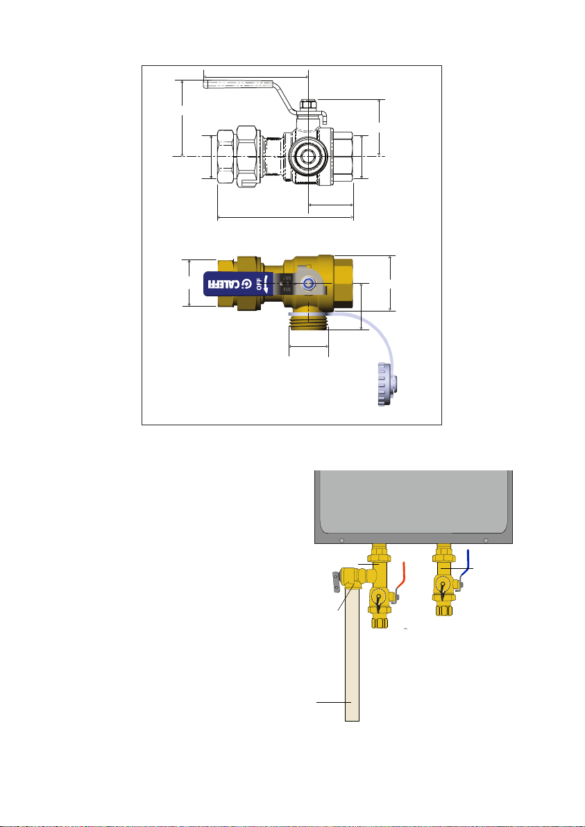
2 3/4”
DRAIN PIPE
(separately
sourced)
HOT WATER
SERVICE VALVE
COLD WATER
SUPPLY
SERVICE VALVE
PRESSURE
RELIEF VALVE
2”
1 1/2”
3/4”
NPTF
3/4”
NPTF
3 11/16”
Low Lead IAPMO R&T
1 1/4”
Installation:
The 290 Series tankless water heater service
valve kit connects directly to the standard
¾” MNPT nipples on the bottom of a typical
tankless water heater.
Attach the ¾” union tailpieces on the 290
valves to the hot (on the left) and the cold
(on the right) nipples of the heater, using
tape or sealant for the NPT threads. Then
attach the valve bodies using the union nuts
and provided.
3/4”
GHT
1 3/16”
1 1/2” dia
1 1/4”
4
Page 5
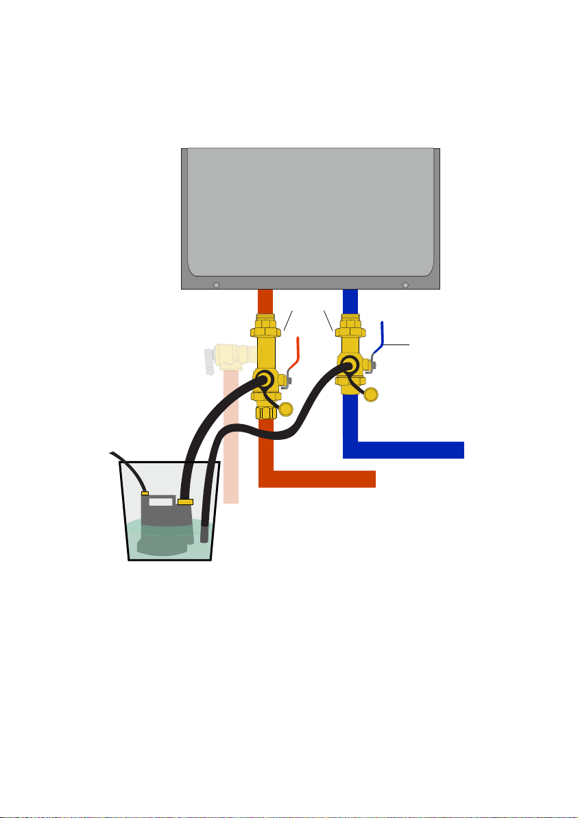
Service
Tankless water heaters require regular flushing and cleaning. Hard water mineral deposits on
the heat exchanger surfaces and sediment buildup reduce heater efficiency and can cause
premature failure.
SERVICE VALVE
ROTATE
SERVICE VALVE
WASHING
MACHINE
HOSE
PUMP CONNECTED TO HOSE
CIRCULATES FLUID THROUGH
HEAT EXCHANGER
CLEANING SOLUTION OR WHITE VINEGAR IN 5 GALLON BUCKET
5
COLD WATER LINE
HOT WATER LINE
Page 6

Pressure relief valve
In the event that the tankless water heater and its piping system exceed designed pressure limits,
the pressure relief valve will automatically open, discharging large amounts of very hot water.
Correctly installed discharge piping and drainage are critical in avoiding a scalding danger or water
damage.
Tighten the included pressure relief with ¾” NPT male connection into the hot water isolation ball
valve ¾” NPT female access port. The outlet connection of the pressure relief valve must face
downward, requiring a vertical discharge pipe. In accordance with IPC code requirement 504.6,
install a suitable-length nipple as a discharge pipe, into the female NPT outlet of the pressure relief valve:
-Do not reduce the ¾” nominal pipe size (NPS) at any length of the piping.
The end of the discharge pipe must remain open and unobstructed.
-The discharge piping must not contain low points, which could trap water. The piping must
allow complete drainage.
-The discharge piping must discharge into a suitable open drain and must not be allowed to
freeze. Please consult IPC 504.6 for additional details.
Annually inspect the end of the discharge piping for signs of relief valve leakage. Carefully lift the
spring-loaded lever and center it horizontally against the identification disc, allowing hot water to
flow from the end of the discharge pipe, into the drain.
CAUTION! Discharged water is extremely hot and can scald! Avoid contact with the water.
After a few seconds, flip the lever back down, closing the valve. If the pressure relief valve fails
to flow water when opened or fails to reseat when closed, contact a qualified installer for valve
replacement.
AVERTISSEMENT: La soupape de décharge peut
évacuer d’importantes quantités d’eau extrêmement
WARNING: The relief valve can discharge
large quantities of extremely hot water. The
discharge pipe must be piped to an adequate
drain, and the discharge on the relief valve shall
be conducted to a suitable place for disposal
when relief occurs by installation of a drain
line with its terminal end discharging through
a six inch (6”) air gap to an approved location
or building drain. Do not connect the drain line
directly to a sewer line. The terminal end of the
drain line shall be plain, not threaded. The drain
line shall be as short and straight as possible
such that the arrangement does not reduce
the relieving capacity of the valve below that
required to protect the heater/boiler. To prevent
water from collecting in the drain line, which
could potentially freeze and cause blockage,
the drain line must be oriented downward such
that the relief valve outlet and drain line will
drain dry. A shut-off valve, reducing coupling,
or other restrictions shall not be installed in
the drain line. The material used for the drain
line must be known to be serviceable for the
purpose and must conform to applicable codes
and standards.
Before operating make sure valve is piped to
a proper drain per instructions. Scalding injury
and/or water damage can occur from either
the manual lifting of the lever or the normal
operation of the valve if it is not piped to a
proper drain.
The BTU/Hr capacity rating of the relief valve
shall meet or exceed the input rating to the
water heater/boiler.
chaude. Le tuyau de refoulement doit être raccordé à
un drain adéquat et l’eau évacuée par la soupape de
décharge dirigée vers un endroit approprié lorsque
l’évacuation se produit au travers de l’installation
d’un tuyau de refoulement dont l’extrémité terminale
se décharge à travers un espace d’air de six pouces
(15,24 cm) vers un emplacement approuvé ou un
drain de bâtiment. Ne raccordez pas le tuyau de
refoulement directement à une conduite d’égout.
L’extrémité du tuyau de refoulement doit être lisse
et non filetée. Le tuyau de refoulement doit être
aussi court et droit que possible, de manière à
ce que l’agencement ne réduise pas la capacité
de décharge de la soupape en dessous de celle
requise pour protéger le chauffe-eau /chaudière.
Pour éviter que l’eau ne s’accumule dans le tuyau
de refoulement, ce qui pourrait potentiellement geler
et provoquer un blocage, le tuyau de refoulement
doit être orienté vers le bas de manière à ce que
la sortie de la soupape de décharge et le tuyau de
refoulement s’écoulent à sec. Une vanne d’arrêt,
un manchon réduit ou d’autres outils de restrictions
ne doivent pas être installés dans le tuyau de
refoulement. Le matériau utilisé pour le tuyau de
refoulement doit être utilisable à cette fin et doit être
conforme aux codes et normes applicables. Avant
d’utiliser la vanne, assurez-vous qu’elle est raccordée
à un système d’évacuation approprié, conformément
aux instructions. Des blessures par ébouillantage
et/ou des dégâts d’eau peuvent se produire soit
en soulevant manuellement le levier, soit en faisant
fonctionner normalement la vanne si elle n’est pas
raccordée à un drain approprié. La capacité en BTU/
Hr (W) de la soupape de décharge doit être égale ou
supérieure à la capacité du chauffe-eau/chaudière.
6
Page 7
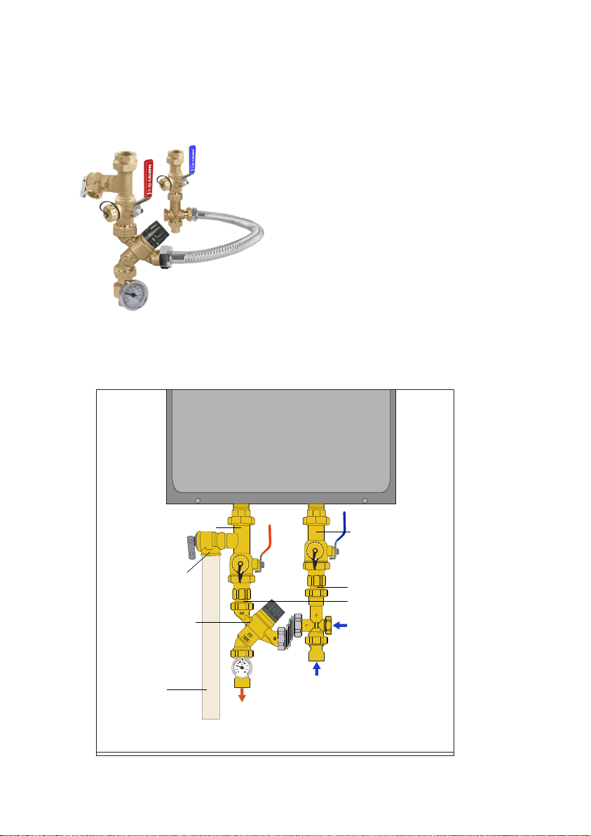
Connecting to Caleffi 520 series TankMixer™
HOT WATER
SERVICE VALVE
COLD WATER
SUPPLY
SERVICE VALVE
RECIRCULATION
WATER
(OPTIONAL)
COLD WATER
INLET
MIXED WATER
OUTLET
PRESSURE
RELIEF VALVE
TANKMIXER
ASSEMBLY
DRAIN PIPE
(separately
sourced)
3/4” MNPT
DOUBLE NIPPLES
(separately sourced)
Caleffi offers Service Valve Kits complete with the 520 TankMixer. This installation and instruction
sheet is included, along with the TankMixer instruction sheet, in the kits listed below.
Code number Connection
KIT290516A ¾" press
KIT290519A ¾" sweat
KIT290510A ¾" NPT female
KIT290517A ¾" PEX crimp
KIT290518A ¾" PEX expansion
The standard 520 TankMixer assemblies can also be field retrofitted to an already installed Caleffi
code KIT290503A Tankless water heater service valve kit. A 3/4” NPT male double nipple (1) is
required to connect the TankMixer water heater 3/4” NPT female connections to the lower 3/4” NPT
female connections on the hot and cold isolation ball valves in the code 290503A.
(1)
7
Page 8

12-2023
Caleffi shall not be liable for damages resulting from stress corrosion, misapplication or
misuse of its products.
Caleffi ne pourra etre tenue responsable des dommages resultant de la corrosion, d’une
mauvaise utilisation ou une mauvaise utilisation des produits.
Caleffi North America, Inc.
3883 West Milwaukee Road
Milwaukee, WI 53208
T: 414.238.2360 F: 414.238.2366
8
 Loading...