

Page 1
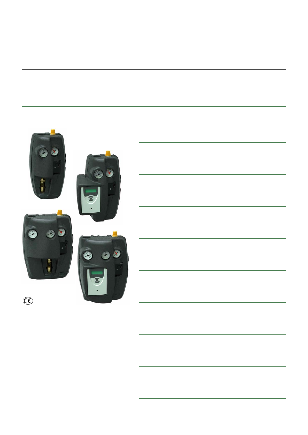
Circulation units
for solar thermal systems, with solar regulator DeltaSol® C+
268-269 series
INSTALLATION AND COMMISSIONING MANUAL
INDEX
28199
Function
Product range
Technical specifications
Characteristic components
Installation
Filling the system
1
2
3
4
5
Function
Circulation units are used on the primary circuit of
solar thermal systems to control the temperature
in the hot water storage. The pump inside the
units is activated by the signal arriving from the
regulator. Moreover, safety and functional devices
for optimum control of the circuit are fitted in the
units.
They are available with flow and return connection
or with return connection only.
Some versions are also complete with the digital
regulator DeltaSol
suitable for the operation and control of 9 different
types of solar thermal systems.
®
C+ for solar thermal systems,
Commissioning
Components
Application diagrams
1
6
7
8
Page 2
NOTICE
The following instructions must be read and understood before installing, commissioning and
servicing the circulation unit.
The safety symbol is used in this manual to draw attention to the respective safety instructions.
The meaning of this symbol is as follows:
N.B! YOUR SAFETY IS INVOLVED. FAILURE IN FOLLOWING THESE INSTRUCTIONS MAY
RESULT IN INJURIES.
- The circulation unit for solar thermal systems must be installed by a qualified technician in compliance with
relevant national and/or local regulations.
- If the circulation unit is not installed, commissioned and serviced correctly in accordance with the instructions
given in this manual, it might not work properly and could put the user in danger.
- Make sure that all connection fittings are watertight.
- When realising hydraulic connections, make sure that threaded connections are not overstressed mechanically.
Over time, excessive stress may cause breakages with hydraulic leaks and damage to property and/or personal injury.
- Water temperatures exceeding 50°C may cause severe burns.
- When installing, commissioning and servicing, take the necessary precautions so that these temperatures will not
be hazardous for people.
CAUTION: Risk of electric shock. Remove the power supply before carrying out any work.
Failure in following these instructions may result in personal injury or damage to
property.
Product range
Code 268050 Circulation unit with return connection 1–13 l/min size 3/4”
Code 269050 Circulation unit with flow and return connection 1–13 l/min size 3/4”
Code 268250 Circulation unit with return connection, with regulator DeltaSol
Code 269250 Circulation uniti with flow and return connection, with regulator DeltaSol
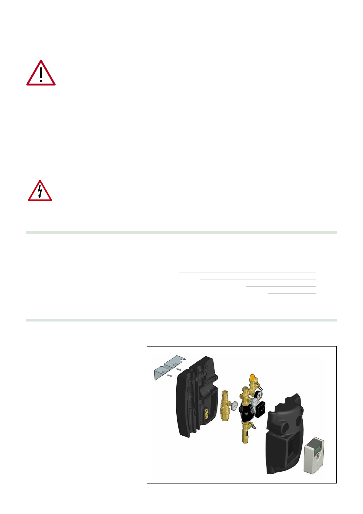
Package content
The package contains:
Circulation units
• The solar circulation unit complete with front
and rear insulation.
• The wall fixing bracket.
Regulator (only for versions complete with)
• Solar regulator DeltaSol®C+.
• 4 temperature probes.
Accessories:
• Bag of 2 M5 screws, S6 screw anchors and
washers.
®
C+ 1–13 l/min size 3/4”
®
C+ 1–13 l/min size 3/4”
2
Page 3
Technical specifications
0
0
H (mm w.g.)
G (m
3
/h)
H (kPa)
0
1
2
3
UPS 15-65
6
5
4
3
2
1
60
50
40
30
20
10
0,2 0,4 0,6 0,8 1,0 1,2 1,4
0
0
H (mm w.g.)
G (m
3
/h)
H (kPa)
0
1
2
3
UPS 15-65
6
5
4
3
2
1
60
50
40
30
20
10
0,2 0,4 0,6 0,8 1,0 1,2 1,4
0
P (W)
G (m
3
/h)
20
30
40
50
60
70
80
0,2 0,4 0,6 0,8 1,0 1,2 1,4
1
2
3
UPS 15-65
Materials
Shut-off valves
Body: brass EN 12165 CW617N
Check valve: brass EN 12164 CW614N
Temperature gauge: steel / aluminium
Air separator device
Body: brass EN 12165 CW617N
Instrument holder
Body: brass EN 12165 CW617N
Seals: EPDM
O-Rings: EPDM
Flow meter
Body: brass EN 12165 CW617N
Transparent level gauge: PSU
Flow indicator: brass EN 12164 CW614N
Hydraulic seals: EPDM
Insulation
Material: EPP
Average thickness: 30 mm
Density: 45 kg/m
Working temperature range: -5–120°C
Thermal conductivity: 0,037 W/(m·K) at 10°C
Reaction to fire (UL 94): class HBF
Performance
Medium: water, glycol solutions
Max. percentage of glycol: 50%
Max. working temperature:
- deaerator side flow: 160°C
- pump side return: 110°C
Max. working pressure: 10 bar
Safety relief valve working temperature range: -30–160°C
Safety relief valve setting: 6 bar (for other settings, see 253 series)
Check valve min. opening pressure (∆p): 2 kPa (200 mm w.g.)
Working temperature range of shut-off and check valve: -30–160°C
Working temperature range of flow meter : -10–110°C
Flow rate adjustment: 1–13 l/min
Flow rate indicator accuracy: ±10%
Pressure gauge scale: 0–10 bar
Temperature gauge scale: 0-160°C
Connections: 3/4” F
Hose connection: 3/4” M
Fill/drain connections: with Ø 15 mm hose connection
Grundfos Solar 15-65 pump
Body: cast iron GG 15/20
Electric supply: 230 V - 50 Hz
3
Max. pressure: 10 bar
Max. temperature: 110°C
Protection class: IP 42
Digital regulator
Electric supply: 230 V - 50 Hz
Nominal power consumption: 1,5 VA (12 V (ac))
4 Pt1000 probe inputs
2 relay outputs with semiconductor with contact rating: 1 A
–
2 temperature probes with working range: -50
200°C
Probe cable working temperature range: -50–70°C
2 temperature probes with working range: -50–200°C
Probe cable working temperature range: -50–180°C
Ambient temperature range: 0–40°C
Protection class: IP 20
Dimensions: 172 x 111 x 49 mm
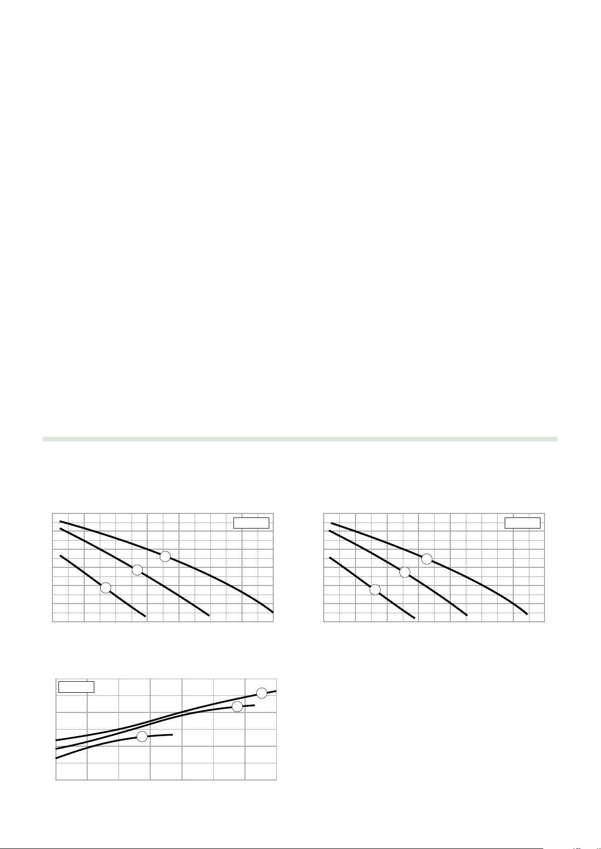
Head available at the circulation unit connections
268 series Flow rate adjustment range 1–13 l/min 269 series Flow rate adjustment range 1–13 l/min
Power consumption
3
Page 4

Characteristic components
1
2
3
4
5
8
9
11
10
16
16
a
a
a
a
a
a
a
a
aaa
a
a
a
a
a
a
a
a
a
a
a
aa
a
a
a
a
a
a
a
a
a
a
aa
a
a
a
a
a
a
a
a
a
a
aaa
a
a
a
a
a
a
a
a
a
a
a
aa
0
20
40
60
80
100
120
140
160
c
o
n
f
o
r
m
e
n
o
r
m
e
I
S
P
E
S
L
0
2
4
6
8
10
bar
CL 2.5
1
13
11
9
7
5
3
l/min
10
a
a
a
a
a
a
a
a
a
a
a
a
aaa
a
a
a
a
a
a
a
a
a
a
a
a
a
a
a
a
a
a
a
a
a
a
a
aa
a
a
a
a
a
a
a
a
a
a
aaa
a
a
a
a
a
a
aa
a
a
a
aaa
a
a
a
a
a
a
aa
a
aa
a
a
a
a
a
a
a
a
a
a
a
a
a
a
a
a
a
a
a
a
a
0
20
40
6080100
120
140
160
0
20
40
6080100
120
140
160
c
o
n
f
o
r
m
e
n
o
r
m
e
I
S
P
E
S
L
0
2
4
6
8
10
bar
CL 2.5
7
9
16
16
1
13
11
9
7
5
3
l/min
1
2
3
4
11
5
8
6
12
13
75° 65°
12°
14
15
1) Grundfos Solar 15-65 circulation pump
2)
Safety valve with adjustable outlet type 253 series
3) Fill/drain cock with control key
4) Instrument holder fitting with pressure gauge
5) Flow meter
6) Deaerator with air vent
7) Flow temperature gauge
8) Return temperature gauge
9) Pre-formed shell insulation
10) Shut-off valve with built-in check valve
11) Connection kit for expansion vessel (optional)
12)
Display with synoptic diagram and temperature indication*
13) Regulating keys*
14) Temperature probe*
15) Stainless steel probe pocket code 257004 (optional)
16) Hose connection
* only for versions with DeltaSol®C+ regulator
4
Page 5

Installation
a
a
a
a
a
a
a
a
aaa
a
a
a
a
a
a
a
a
a
a
a
aa
a
a
a
a
a
a
a
0
20
40
6080100
120
140
160
0
20
40
6080100
120
140
160
c
o
n
f
o
r
m
e
n
o
r
m
e
I
S
P
E
S
L
0
2
4
6
8
10
bar
CL 2.5
A
1
13
11
9
7
5
3
l/min
• Fix the wall support bracket, using the fixing screws supplied in the pack (1).
• Insert the rear insulation, through the notch provided (2).
• Insert the unit components in the insulation using the special notches made in the bracket and the slots in the components. Block the
components on the bracket, pulling them downwards to that they click into their housing (3).
• Establish the position for installing the expansion vessel at a distance allowed by the length of the flexible pipe, using the bracket provided.
The latter allows the use of expansion vessels with a maximum capacity of 24 l, see the instructions concerning the accessories (4).
• Install the pipes of the whole system and connect the solar unit. Secure the components and the pipes to the rear insulation.
Fully tighten all the fittings.
• The unit’s threaded fittings are tightened and tested in the assembly phase at the factory. However, when commissioning it is necessary to
check the seal of the fittings, performing a pressure test.
• Make the electrical connections of the system, as specified in the regulator instruction manual. Apply the front part of the insulation.
1
Filling the system
• Open the shut-off valve coupled with the automatic air vent, installed in the highest point of the solar thermal system (1).
• Open the shut-off and check valves, turning the control stems (2) through 45° (do not remove the temperature gauges).
• Fill by means of a pump, using the cock (A) located at the lowest point of the system, until air no longer comes out of the air vent (1). If the
solar thermal system is made using water premixed with antifreeze, any top-ups must be carried out using a mixture with the same
proportions.
• Close the shut-off valve of the air vent (3).
• Close the cock (A).
1
234
2
3
5
Page 6

Flushing the system
a
a
a
a
a
a
a
a
a
a
a
a
aaa
a
a
a
a
a
a
a
a
a
a
a
aa
a
a
a
a
a
a
a
0
20
40
6080100
120
140
160
0
20
40
6080100
120
140
160
c
o
n
f
o
r
m
e
n
o
r
m
e
I
S
P
E
S
L
0
2
4
6
8
10
bar
CL 2.5
1
13
11
9
7
5
3
l/min
Close the flow meter regulating ball valve (1). Then open the fill/drain cock, by turning it counter-clockwise using the cap with control key (2).
•
• By means of a (separate) external pump applied on the fill/drain cock of the safety unit (3), let the medium flow through the solar panels and
the heat exchange circuit until the medium comes out of the fill/drain cock (4) of the flow meter.
• Briefly open the flow meter ball valve (4) to expel all the air from the system.
• Leave the external pump running on the system for a few minutes to ensure correct flushing.
1
34
Commissioning
• Close the flow meter fil/drain cock (1) and increase the system pressure up to the maximum design pressure, by means of the external filling
pump applied to the fill/drain cock of the safety unit.
equipped with control key.
• Open the valves of the unit (3) and switch on the pump of the solar circulation unit (do not remove the temperature gauges).
• Let the water circulate for a certain time, then check the water tightness.
• Open the air vent again, installed in the highest point of the solar thermal system, repeating the deaeration phase, briefly activating the
circulation pump.
• Restore the desired working pressure with the filling pump.
• The system flow rate may be changed by means of the flow meter (4). This modulation is performed by the ball valve with which it is
equipped (see respective characteristics). To regulate/limit the flow rate it is recommended to follow the indications of the solar panel
manufacturer.
• After the first operating hours, the solar thermal system must be deaerated again, both in the highest point and on the air separator (on the
versions where this is contemplated).
Once deaeration has been completed, check the system pressure and if necessary restore to the desired working pressure.
2
When this pressure is reached (2), close the fill/drain cock of the safety unit using the cap
1234
Draining the system
• The draining operation is necessary if the system has been filled only with water and there is a risk of frost.
• Open the shut-off and check valves, turning the ball valve through 45°. Open the air vents in the highest point.
• Open the drain cock at the lowest point of the system.
6
Page 7

Shut-off and check valves
13
11
9
7
open closed
2
3
0
°
F
1
1
0
°
C
Flow meter
The shut-off valves are equipped with a built-in check valve,
positioned inside the ball.
1. To allow the passage of the fluid
in both directions, the ball valves
must be opened at 45°, using a
9 mm fixed wrench.
The check valve is opened by the
ball, see figure (A).
2. In normal system operation, the
ball valves must be completely
open.
A
The flow meter is a floating gauge flow rate measurator with a
built-in regulating ball valve.
It works within the range of 1–13 l/min.
The flow meter must be fitted in a vertical position only.
Captive nut
Flow rate adjustment
Fitting 1/2” F
Graduation
Thermometric
label
Fitting 3/4” F
Air separator device
The solar circulation units with flow and return connection are
equipped with an air separator device on the flow line. The gases
separated from the thermal carrier medium collect at the top of the
deaerator.
The collected gases must be evacuated from time to time (every
day after commissioning and afterwards, depending on the
quantity of air, once a week or once a month) using the manual air
vent with a suitably sized screwdriver.
To maintain optimal efficiency of the solar thermal system,
afterwards, it is necessary to
vent the system every six
months by using the deaerator.
A thermometric label is placed on the back of the flow meter to
signal if the maximum permitted temperature (110°C) has been
exceeded:
white color = temperature not exceeded;
dark color = maximum temperature exceeded.
The label removal makes the manifacturer warranty on the device
expire.
The level is taken from the
top edge of the float.
➜
Correction for liquids with different density
The variation in the flow rate reading remains within the range of
accuracy indicated (±10%), for glycol percentages up to 50%.
Full closing and opening of the valve
➜
N.B! Use only a
wrench to regulate the flow
9mm fixed
meter.
The valve can be
completely opened or
closed.
A slot on the obturator
stem indicates the
status of the valve.
7
Fully closed
Fully open
AB
Page 8

Application diagrams
Shut-off valve
Pump
Air vent
Expansion vessel
Temperature gauge
Safety relief valve
2
a
a
a
a
a
a
a
a
a
a
aaa
a
a
a
0
20
40
6080100
120
140
160
c
o
n
f
o
r
m
e
n
o
r
m
e
I
S
P
E
S
L
0
2
4
6
8
10
bar
CL 2.5
c
o
n
f
o
r
m
e
n
o
r
m
e
I
S
P
E
S
L
0
2
4
6
8
10
bar
CL 2.5
a
a
a
a
a
a
a
a
a
a
aaa
a
a
a
0
20
40
6080100
120
140
160
c
o
n
f
o
r
m
e
n
o
r
m
e
I
S
P
E
S
L
0
2
4
6
8
10
bar
CL 2.5
c
o
n
f
o
r
m
e
n
o
r
m
e
I
S
P
E
S
L
0
2
4
6
8
10
bar
CL 2.5
1
13
11
9
7
5
3
l/min
1
13
11
9
7
5
3
l/min
a
a
a
a
Shut-off valve
Pump
Air vent
Expansion vessel
Temperature gauge
Safety relief valve
Automatic
filling
2
a
a
a
a
a
a
a
a
aaa
a
a
a
a
a
a
a
a
a
a
a
aa
a
a
0
20
40
6080100
120
140
160
0
20
40
6080100
120
140
160
c
o
n
f
o
r
m
e
n
o
r
m
e
I
S
P
E
S
L
0
2
4
6
8
10
bar
CL 2.5
0
20
40
6080100
120
140
160
c
o
n
f
o
r
m
e
n
o
r
m
e
I
S
P
E
S
L
0
2
4
6
8
10
bar
CL 2.5
c
o
n
f
o
r
m
e
n
o
r
m
e
I
S
P
E
S
L
0
2
4
6
8
10
bar
CL 2.5
0
20
40
6080100
120
140
160
c
o
n
f
o
r
m
e
n
o
r
m
e
I
S
P
E
S
L
0
2
4
6
8
10
bar
CL 2.5
c
o
n
f
o
r
m
e
n
o
r
m
e
I
S
P
E
S
L
0
2
4
6
8
10
bar
CL 2.5
1
13
11
9
7
5
3
l/min
1
13
11
9
7
5
3
l/min
1
13
11
9
7
5
3
l/min
a
a
a
a
a
a
a
8
 Loading...