

Page 1
www.caleffi.com
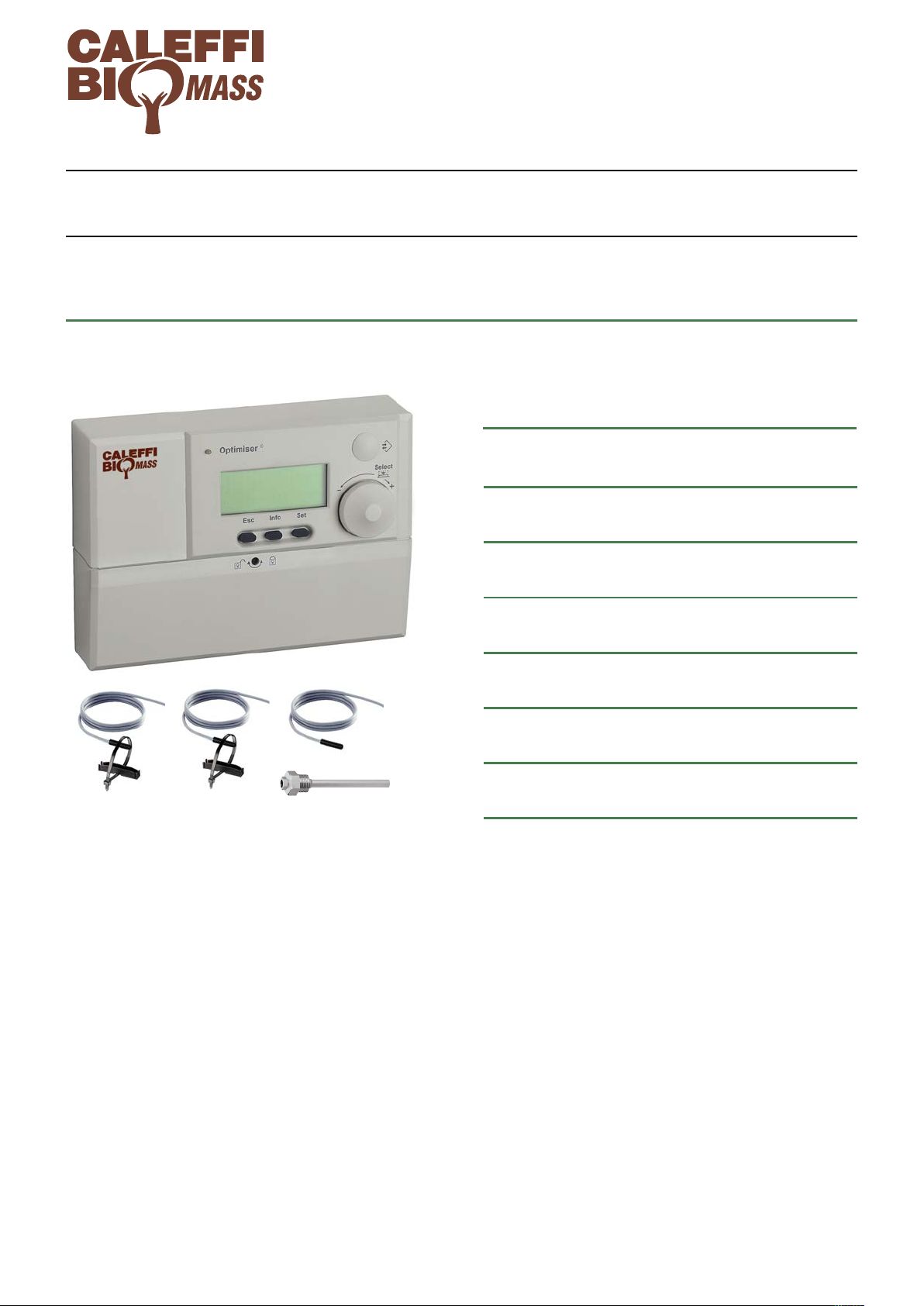
OPTIMISER®digital regulator
for heating systems with solid fuel generator
18146.01EN
© Cop yr igh t 2 014 Ca lef fi
INSTALLATION AND COMMISSIONING MANUAL
CONTENTS
Function
Warnings
Technical data
Display and commands
General functions
1522 series
1
2
2
4
4
Function
®
The OPTIMISER
possible to combine a solid fuel generator with another type
of generator already present in the heating system.
The digital regulator automatically manages the two
generators, receiving the signal from the probes and
activating the pumps, the motorized diverter valves in the
system, according to the heating circuit needs.
Depending on the type and quantity of installed probes, the
regulator supports the following system solutions:
- heating;
- production of domestic hot water by means of storage or
instantaneous with plate heat exchanger;
- management of inertial water storage in parallel on the
heating circuit or alternatively management of an
independent solar system and direct inertial water
storage.
digital regulator code 152200 makes it
Available programs
Hydraulic diagrams of programs
5
7
1
Page 2
WARNINGS
The following instructions must be read and understood before installing, commissioning and
maintaining the regulator.
The safety symbol is used in this manual to draw attention to the relative safety instructions. The
meaning of this symbol is as follows:
CAUTION!
YOUR SAFETY IS INVOLVED. FAILURE TO FOLLOW THESE INSTRUCTIONS MAY
RESULT IN INJURY.
- The digital regulator must be installed by a licensed installer in accordance with national regulations and/or
relevant local requirements.
- If the digital regulator is not installed, commissioned and maintained correctly in accordance with the instructions
in this manual, then it might not work properly and may endanger the user.
CAUTION: Risk of electric shock. The rear panel is live. Cut off the electric supply
before carrying out any work. Failure to follow these instructions may result in
personal injury or damage to property.
LEAVE THIS MANUAL AS A REFERENCE GUIDE FOR THE USER
Technical data
Regulator
Electric supply: 230 V (ac) ±10%; 50-60 Hz
Power consumption: 5,5 VA
Output signals: 10 relay contacts for heating
Contact rating: 250 V (ac), 8 (2) A (max 9 A in total)
Protection class: II
Protection class: IP 40
Clock data retention with no electric supply: 24 h
EEPROM data retention with no electric supply: permanent
Ambient conditions
Ambient temperature:
Operation: 0–55°C EN 60721-3-3 Cl. 3K3, max. humidity 85%
Transportation:-10–70°C EN 60721-3-2 Cl. 2K2, max. humidity 95%
Storage: -5–50°C EN 60721-3-1 Cl. 1K2, max. humidity 95%
When the solid fuel generator is equipped with an anti-condensation valve, it is good practice to set the minimum
working temperature of the solid fuel generator (TSG, settable in the regulator menu) to a value at least 2°C higher than
the anti-condensation valve setting.
Temperature probe* for solid fuel generator flow, domestic
water storage, domestic heat exchanger, inertial water storage
in parallel on the heating system, solar water storage.
NTC type
Working range: -20–100°C
Two-wire cable
Temperature probe* for solar collector
Pt1000 type
Cable length: 3 m
Cable SIHF,
Cross section: 2 x 0,5 mm
Max working temperature: 180°C
*The use of the probes is specified in the “Available programs”
heading on page 5.
2
- Anti-condensation valve setting: °C
- Minimum working temperature of the
solid fuel generator (TSG, working temperature range: 20–85°C): °C (factory setting: 55°C).
It is good practice to compile the two blank fields to facilitate any system checks to be performed.
2
Page 3
NTC probes* resistance table: for solid fuel generator flow, domestic water storage, domestic heat exchanger, inertial water
100 23 1/2”
ø 6,4
A
C
B
650 3
L (m)
B
A
AB
628 2
L (m)
B
A
AB
1,530
55 9 11
L (m)
B
A
C
D
D
43 17 1/4”
ø 6,4
C
B
A
storage in parallel on the heating system, solar water storage.
°C
-20
-18
-16
-14
-12
-10
-8
-6
-4
Pt1000 probe* resistance table: for solar collector.
Ω
14616
13211
11958
10839
9838
8941
8132
7405
6752
°C
-2
±0
+2
+4
+6
+8
+10
+12
+14
Ω
6164
5634
5155
4721
4329
3974
3652
3360
3094
°C
+16
+18
+20
+22
+24
+26
+28
+30
+32
Ω
2852
2632
2431
2247
2079
1925
1785
1657
1539
°C
+34
+36
+38
+40
+42
+44
+46
+48
+50
Ω
1430
1331
1239
1154
1076
1004
938
876
819
°C
+52
+54
+56
+58
+60
+62
+64
+66
+68
Ω
767
718
673
631
592
556
522
491
462
°C
+70
+72
+74
+76
+78
+80
+82
+84
+86
Ω
434
409
386
364
343
324
306
290
274
°C
+88
+90
+92
+94
+96
+98
+100
Ω
260
246
233
221
210
199
189
°C
-10 961 65 1252
-5 980 70 1271
0 1000 75 1290
5 1019 80 1309
10 1039 85 1328
15 1058 90 1347
20 1078 95 1366
25 1097 100 1385
30 1117 105 1404
35 1136 110 1423
40 1155 115 1442
45 1175 120 1461
50 1194 140 1536
55 1213 160 1611
60 1232 170
CAUTION
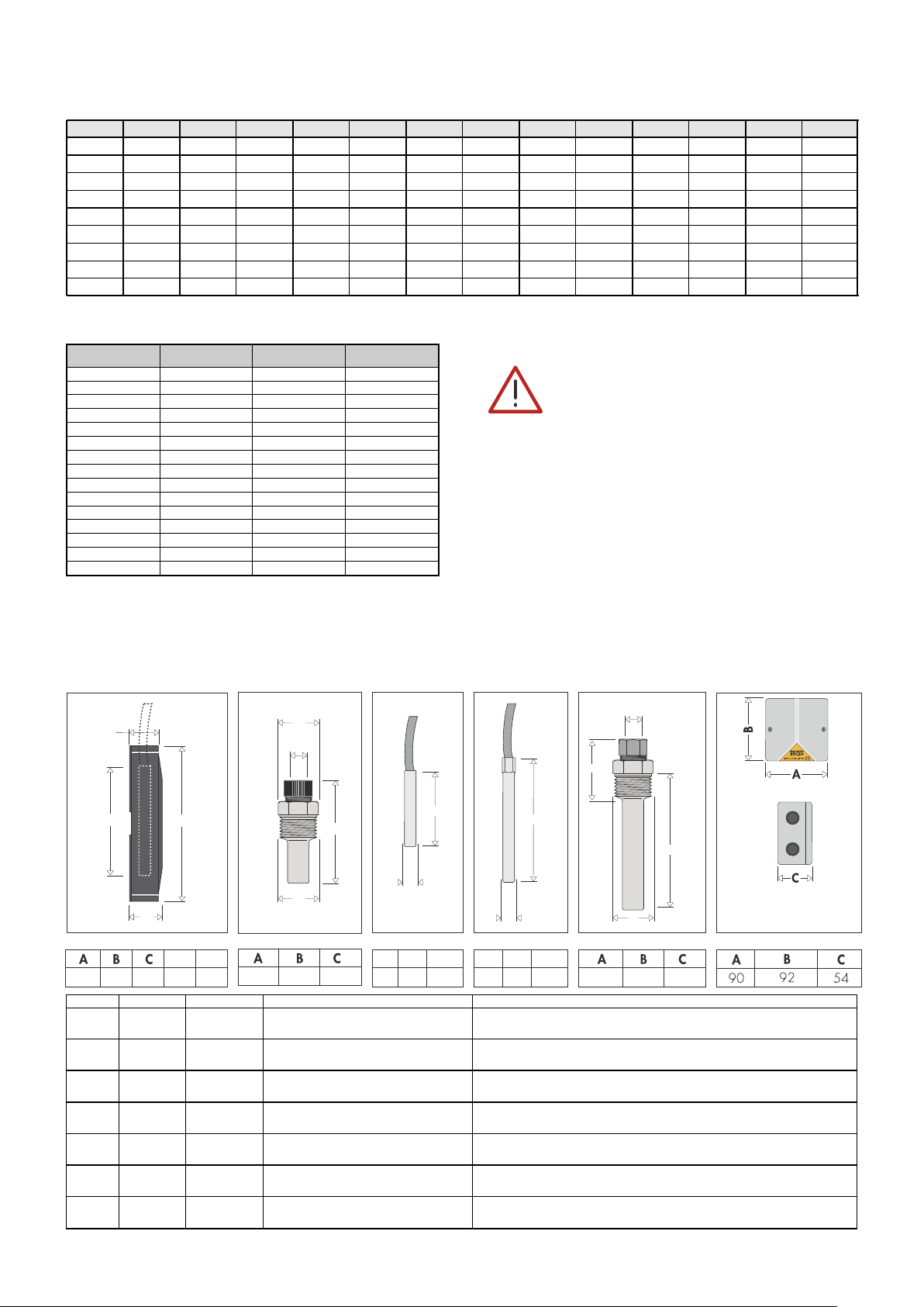
Install Pt1000 probe, with red silicone sheath cable (Tmax 180°C), on the solar collector.
Dimensions
NTC probe and contact probe
holder code 150009
Ω
°C
Immersion pocket
code 150029
Ω
NTC probe
code 150006
Pt1000 probe
code 257006
Probe connection
The cable connecting probes to the regulator must be
installed in a dedicated raceway. If the connection
cable shares the raceway with other power cables, an
earthed shielded cable must be used.
Any alteration to the wiring of the regulator could
result in electrical disturbance.
After performing work on the wiring, the regulator
must be reset by cutting off the electric supply for a
few seconds. Cable length can be increased to 100 m
using a 1 mm
2
cross section cable.
Immersion pocket
code 257004
Relay box
code F29525
Probe Type Supply Standard application Optional application
S1* NTC series
S2* NTC optional - probe code 150006 + pocket code 257004
S3* NTC optional - probe code 150006 + pocket code 150029
S4* NTC series
S5* NTC series
Sol2* NTC optional - probe code 150006 + pocket code 257004
Sol1* Pt1000 optional -
*The use of the probes is specified in the “Available programs” heading on page 5.
See instruction sheet,
code 28134
probe + contact probe holder:
code 150009
immersion pocket code 150029
probe code 150006 +
pocket code 257004
probe + contact probe holder:
code 150009
3
immersion type: probe code 257006 +
pocket code 257004
-
-
Page 4
5
-
+
Optimiser
1
2
3
4
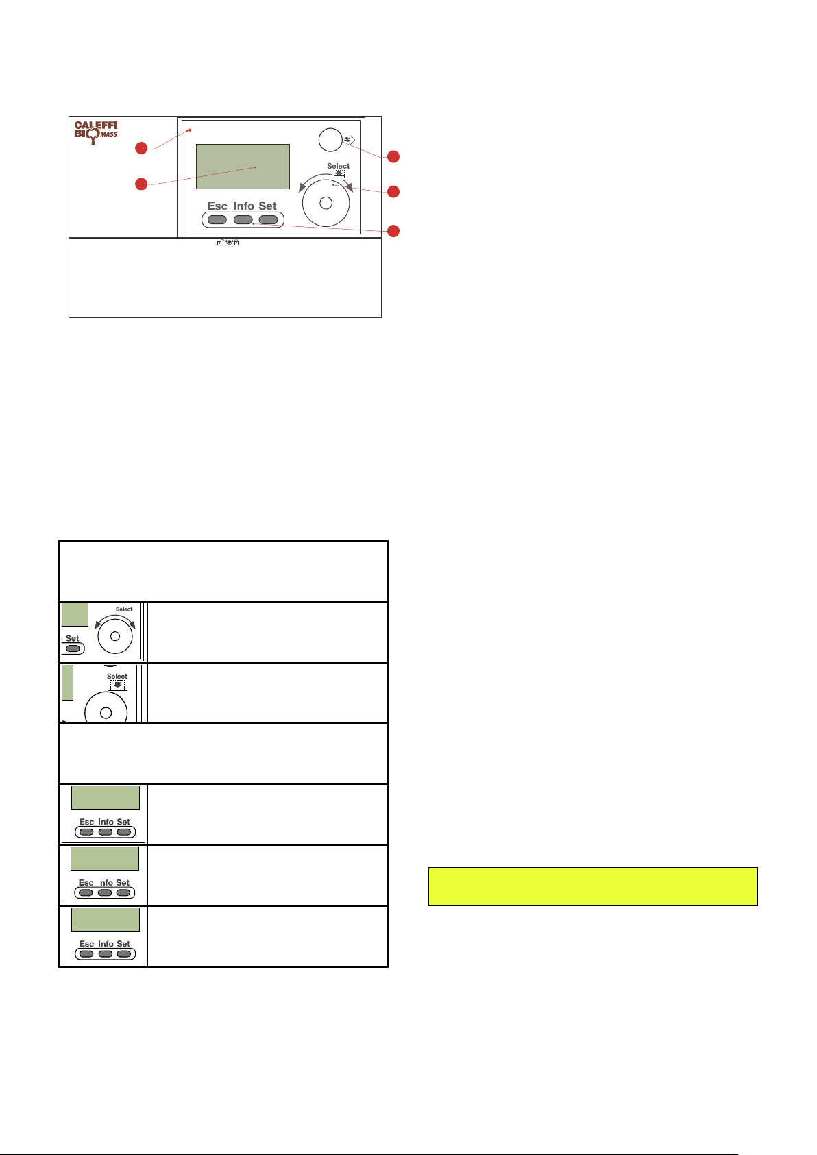
Display and commands
-
+
-
- -
General functions
Display
The regulator is equipped with a display to read and program the
control parameters, such as cut-in temperatures, function
activation delay times, thermal disinfection programs, solar system
control, etc. All the system’s functional parameters can be
configured to match individual requirements by means of the
“Select” knob and the three function keys.
Block protection function “Block Protect.”
When it is powered on, the regulator performs an initial check,
activating the valves and pumps to which it is connected. The
message “Block Protect.” appears on the display.
Pump and diverter valve anti-clog function
To prevent clogging of the pumps and diverter valves due to
prolonged stoppages, the regulator activates them for 60 seconds
after each period of 24 consecutive hours of disuse.
Control description
1- Operating status indicator LED.
2- Mini DIN connector on front of panel for PC connection.
3- Menu display.
4- Select knob: selection of functions menu and parameter editing.
5- Function keys
Display
The display (3) shows the text with the main operating information.
In the absence of control signals, after four minutes the display
reverts to the initial page.
Select knob and function keys
Select knob (4): can be rotated or pressed
Turn the Select knob clockwise or
anticlockwise to select the options of the
function menu or to modify the values of the
various user-settable parameters.
Press the Select knob to open the submenu
relative to the selected option.
Function keys (5): can be pressed
Esc: change the display of the selected menu
point and return to the previous menu level
Frost protection
When the solid fuel generator flow temperature reaches a minimum
user-settable value, the regulator activates the primary side pump
to prevent the circuit from freezing.
Anti-legionella function (programs 5 and 8 only)
The regulator keeps the domestic water storage at the minimum set
temperature and raises the temperature in order to perform thermal
disinfection in accordance with customizable times.
Instantaneous domestic hot water production (programs 6 and
9 only)
The regulator manages the instantaneous domestic hot water
production by means of a second heat exchanger and, if
necessary, it sends the water to the boiler for thermal integration by
means of the (optional) SOLARINCAL kit (code 265359).
Overtemperature safety function
The regulator is equipped with a solid fuel generator
overtemperature monitoring function.
When the user-settable emergency temperature is reached on the
solid fuel generator, the regulator generates an alarm signal and
starts the pumps to dissipate the excess heat to the system or to an
emergency user service. This latter function can be activated by
means of a specific menu item. In this case, it is necessary to install
a diverter valve, driven by the regulator, to transfer the flow to the
emergency user service.
Probe control
Solid fuel generator flow temperature sensor error
When the working temperature range detected is below 0°C or
above 110°C, the following status is activated automatically: pumps
OFF, while the display shows the message “probe error” and the
LED flashes green and red alternately.
Info: displays brief information on the current
menu point
Set: executes the change, confirming the
selected parameter value
LED
The LED (1) gives status information by means of a multicoloured
diode:
- flashing green: regulator initialisation
- steady green: regulator operating
- flashing green/red: regulator operating with probe error or alarm
- flashing red: regulator checking loop
- steady red: regulator error.
To set parameters use the document
“MENU LIST” code 28180 supplied in the pack
4
Page 5

Available programs
ON
1 2 3 4
ON
12 34
ON
1 2 3 4
ON
1 2 3 4
ON
12 34
ON
12 34
HIGH VOLTAGE
JUNCTION BOX
LOW VOLTAGE
JUNCTION BOX
HIGH VOLTAGE LOW VOLTAGE
®
OPTIMISER
digital regulator code 152200 can be used in accordance with 6 different system configurations (programs), comprising a basic
factory-set configuration and 5 optional configurations selectable by means of the table shown below and activatable by means of the dipswitches
on the regulator. To access the dipswitches open the cover under the display. The regulator is supplied with the factory settings and probes
required to perform basic program 4.
Program
configuration
Description Probes utilised Position of
program
selectors
Software
code
Hydraulic
diagram
on page
(dipswitches)
4
(basic factory set
program)
Heating + management of
inertial water storage in
parallel on the heating
system*
S1 - - S4 S5 PR83 7
Heating and domestic hot water
5
with storage + management of
inertial water storage in parallel
S1 S2 - S4 S5 PR84 8
on the heating system*
Heating and instantaneous
6
domestic hot water + management
of inertial water storage in parallel
S1 S3 - S4 S5 PR85 9
on the heating system*
Heating with direct inertial
7
water storage with tank-in-
tank domestic hot water
S1 - Sol 1 Sol 2 - PR86 10
production, solar system
Heating with direct inertial
8
water storage, domestic hot
water storage integrated with
S1 S2 Sol 1 Sol 2 - PR87 11
solar system
Heating with direct inertial water
9
storage integrated with solar
system, instantaneous domestic
S1 S3 Sol 1 Sol 2 - PR88 12
hot water production
Programs 1,2 and 3 (not listed in the table but however available) are functionally equivalent to programs 7,8 and 9 respectively but without
thermal solar components. For specific setting (dipswitches and probes to be used) please see instruction sheet 28169 (www.caleffi.com).
NOTE The probes are all of the NTC type (grey cable) except for probe Sol1 utilised by solar programs 7, 8 and 9, which
is type Pt1000 with red cable.
* refer to operating logic of program “management of inertial water storage in parallel on the heating system” on the next page.
Location of cable glands
When making the electrical connections, observe the following sequence for wiring the terminal board.
- If the regulator is to be wall mounted with the consequent use of the supplied cable glands and downward cable outlet, regulations require that just
one cable can transit through each hole of the cable gland, therefore a maximum of 6 high voltage cables and 6 low voltage cables can be utilised.
It is therefore recommended to comply with the following table of connections and use two additional junction boxes complete with suitable inlet and
outlet cable glands, in accordance with the diagram given. The earth connection must be made in the junction box.
- If the regulator is installed in an electrical cabinet, the cable outlet must be via the openings at the rear of the unit, always keeping high and
low voltage cables separated. The earth connection must be made in the electrical cabinet.
Electric connection
Electric supply 2x1,5 mm
Pump P1
Pump P2
Gas generator contact C
Solid fuel generator contact K
Diverter valve V1
Diverter valve V4 to optional dissipator
Domestic priority diverter valve V2 or domestic priority
HIGH VOLTAGE
Valve V5 for loading the inertial water storage in
Probe S5 or solar water storage probe Sol2 2x0,75 mm
Probe S4 or solar collector probe Sol1 2x0,75 mm
Room thermostat TA or adjustment thermostat TR contact
Domestic water storage probe S2 or probe S3 on
LOW VOLTAGE
diverter valve V3
SOLARINCAL type diverter valve
parallel or solar circuit pump Psol
Probe S1 2x0,75 mm
domestic heat exchanger outlet
Flow switch F 2x0,75 mm
Recommended electrical cable:
nr. wires for cross-section
4x1 mm
4x1 mm
4x1 mm
6x1 mm
2x1 mm
2x1 mm
2x0,75 mm
2
2
2
2
2
2
2
2
2
2
2
2
Dedicated
cable gland
5
A
B
C
D
E
F
G
H
I
L
M
N
Page 6

HEATING
BOILER
HEATING
BOILER
SOLID FUEL
GENERATOR
SOLID FUEL
GENERATOR
SOLID FUEL
GENERATOR
SOLID FUEL
GENERATOR
HEATING
BOILER
HEATING
BOILER
*Operating logic of program “management of inertial water storage in parallel on the heating system”.
In accordance with construction and system regulations or depending on system management requirements it may be necessary to use an
inertial water storage on the heating system.
The regulator is supplied as standard with the parameters and probes required to manage a heating system with inertial water storage in
parallel on the heating system.
The operating logic is shown in the adjacent figures:
Phase 1: direct supply to system. With a thermal energy demand
from the room thermostat, the regulator activates the solid fuel
generator and connects it, once it is able to supply energy, directly
to the secondary circuit bypassing the inertial water storage in
parallel. Valve V5 connects the inertial water storage in parallel with
the heating system so that it can receive any excess heat energy.
Phase 2: loading of water storage with system idle. When the
room heating demand is met, with the thermostat no longer
requesting heat energy but with the solid fuel generator still
capable of providing it (e.g. due to an energy surplus caused by
excessive fuel stoking), the regulator connects the solid fuel
generator to the parallel water storage, which thus serves to store
the surplus heat energy.
Phase 1: direct supply to system
Phase 2: loading of water storage
with system idle
Phase 3: unloading of water storage with generator off. The
parallel water storage is used as an energy source at the time of the
next room heating demand if the solid fuel generator is not
operating, not yet at working temperature or not stoked with fuel.
The previously accumulated heat energy is thus drawn from the
parallel water storage.
Phase 4: gas boiler activation.
Only when the solid fuel generator is not operating and the parallel
water storage has no energy reserve, it is necessary to start the gas
boiler, which at that point is the only device able to supply heat
energy to the heating system. Valve V5 isolates the parallel water
storage from the rest of the circuit to avoid loading it with heat
energy delivered by the gas boiler.
Phase 3: unloading of water
storage with generator off
Phase 4: gas boiler activation
6
Page 7

Hydraulic diagrams of programs
ON
12 34
V5
M M
S5
D
D
T
P1
P2
C
V1
RT
D
K
S1
K
S1
S4
V4
V5 S5 S4
F29525
KV4CP1 P2 C V1
S1
RT
-
+
Optimiser
Regulator 152200
V5=Zone valve 6443..3BY
Com.
Relè 1 VA
8 VA
LN
N10
Heating system
HEATING
BOILER
Optional
dissipator
Closed vessel
Open vessel
wiring to be made
Wiring diagram
L Live
N Neutral
L’
1
Live jumper
2 ON pump P2
ON pump P1
3’ Gas generator C
3 Gas generator C
N Neutral common
4 ON diverter valve V1
5
NO
ON diverter valve V4
to optional dissipator
5
NC
6’ Solid fuel generator K
10 ON valve V5 to load the
parallel water storage
N Neutral common
6’ Solid fuel generator K
y1 Probe S1
y
2 Probe S1
y4 Probe S5
y5 Probe S5 and S4
common
y6 Probe S4
x2 Room thermostat
RT contact
x3 Room thermostat
RT contact
SOLID FUEL
GENERATOR
SOLID FUEL
GENERATOR
INERTIAL
WATER
STORAGE
IN PARALLEL
Wiring diagram of F29525
relay box - 230 V ˜ 50 Hz
V5
D
V5
D
Program 4 (software code PR83): BASIC FACTORY PROGRAM
Heating + management of inertial water storage in parallel on the heating system
Number of probes utilised: 3
Probe S1 located on solid fuel generator flow
Probe S5 located on heat exchanger inlet on secondary side of circuit
Probe S4 located on the inertial water storage in parallel on the heating system
Operating principle
The 1522 series regulator automatically manages a system composed of a solid fuel generator, integration gas boiler and inertial water storage
in parallel on the heating system.
On the request of room thermostat RT (not supplied in the pack), the regulator activates the solid fuel generator with priority using contact K
(for generators that can be activated electrically). When the minimum working temperature of the solid fuel generator has been reached (as
detected by probe S1), the regulator starts pump P1, diverts valve V1 to connect the heat exchanger to the system and starts pump P2. With
the solid fuel generator off or not yet at working temperature, the regulator starts the integration boiler by means of contact C, stopping pumps
P1 and P2 and diverting diverter valve V1 to the boiler.
In the case of solid fuel generator overtemperature, the regulator sends the flow rate of the secondary circuit either to the system (in the
presence of room thermostat demand) or to an optional dissipation system, if present.
The inertial water storage in parallel is managed in accordance with the logic described on page 6. By means of diverter valve V5 (not supplied
in the pack, e.g.: Caleffi 6443..3BY series + relay box code F29525) the regulator manages all phases of loading and unloading of the water
storage, which is kept closed only if the gas boiler has been activated. Connection of the parallel water storage to the rest of the system is
managed by the regulator by comparing the temperature readings of probes S1 (located on the solid fuel generator flow pipe), S5 (located on
the heat exchanger return line) and S4 (located on the parallel water storage). For probe S5 it is advisable to use the following working
set-points: 45°C for radiator systems, 30°C for radiant panel systems. The gas boiler starts when the solid fuel generator temperature is below
the minimum working temperature TSG (measured by probe S1) and the heat exchanger return temperature TR (measured by probe S5) is 5°C
below the value set on the regulator (TR set, fixed hysteresis value 5K).
7
Page 8

-
+
Optimiser
V5
F29525
KV2CP1 P2 C V1
RT
S2
S1
S5 S4
V5
K
S1
K
S1
M M
D
D
T
P1
V2
P2
C
V1
S2
RT
D
S4
S5
Com.
Relè 1 VA
8 VA
LN
N10
Wiring diagram
L Live
N Neutral
L’ Live jumper
1 ON pump P1
2 ON pump P2
4 ON diverter valve V1
5
NO
ON diverter valve V2
for domestic priority
5
NC
10 ON valve V5 to load
the parallel water
storage
y1 Probe S1
y
2 Probe S1
y4 Probe S5
Probe S4
y5 Probe S5 and
S4 common
y6
x2 Room thermostat
RT contact
x3 Room thermostat
RT contact
x4 Domestic water
storage probe S2
x5 Domestic water
storage probe S2
wiring to be made
Heating
system
Domestic
water
system
DCW
DHW
Open vessel
Closed vessel
6 Solid fuel
generator K
3 Gas generator C
3’ Gas generator C
N Neutral common
6’
Solid fuel
generator K
N Neutral common
SOLID FUEL
GENERATOR
SOLID FUEL
GENERATOR
INERTIAL
WATER
STORAGE
IN PARALLEL
HEATING
BOILER
Wiring diagram of F29525
relay box - 230 V ˜ 50 Hz
Regulator 152200
V5=Zone valve 6443..3BY
V5
D
V5
D
ON
1 2 3 4
Program 5 (software code PR84)
Heating, domestic hot water with storage + management of inertial water storage in parallel on the heating system.
Number of probes utilised: 4
Probe S1 located on solid fuel generator flow
Probe S2 (not supplied in the pack) located on domestic water storage
Probe S5 located on heat exchanger inlet on secondary side of circuit
Probe S4 located on the inertial water storage in parallel on the heating system
Operating principle
The 1522 series regulator automatically manages a system composed of a solid fuel generator, integration gas boiler, inertial water storage in
parallel on the heating system and domestic hot water production by means of a water storage.
When the minimum working temperature of the solid fuel generator has been reached (as detected by probe S1), the regulator starts pump P1,
diverts valve V1 to connect the heat exchanger to the system and starts pump P2. With the solid fuel generator off or not yet at working
temperature, the regulator starts the integration boiler by means of contact C, stopping pumps P1 and P2 and diverting diverter valve V1 to the boiler.
In the case of a solid fuel generator overtemperature, the regulator sends the flow rate of the secondary circuit either to the system (in the
presence of a room thermostat demand) or to the domestic water storage if it is not yet at
operating temperature or lower than the limit temperature. The domestic water storage is
maintained at operating temperature by probe S2 and priority diverter valve V2. The regulator
performs thermal disinfection of the domestic water storage in accordance with four
user-selectable preset programs, keeping it for two hours at the disinfection temperature
“Legio.-Temp”, settable in the range 40–75°C. The user can anyway add further disinfection
periods (designated TP points in the menu).
The inertial water storage in parallel is managed in accordance with the logic described on
page 6. By means of diverter valve V5 (not supplied in the pack, e.g.: Caleffi 6443..3BY series
+ relay box code F29525) the regulator manages all phases of loading and unloading of the
water storage, which is kept closed only if the gas boiler has been activated. Connection of the parallel water storage to the rest of the system
is managed by the regulator by comparing the temperature readings of probes S1 (located on the solid fuel generator flow pipe), S5 (located
on the heat exchanger return line) and S4 (located on the parallel water storage). For probe S5 it is advisable to use the following working
set-points: 45°C for radiator systems, 30°C for radiant
minimum working temperature TSG (measured by probe S1) and the heat exchanger return temperature TR (measured by probe S5) is 5°C below the
value set on the regulator (TR set, fixed hysteresis value 5K).
8
Program
0 No disinfection
1 Mon. 2-4
2 Sat. 10-12
3 Sun. 10-12
4 Mon. and Wed. 2-4
Disinfection
day
Disinfection
time slot
panel systems. The gas boiler starts when the solid fuel generator temperature is below the
Page 9

-
+
Optimiser
V5
V4
M M
D
K
S1
K
S1
D
D
T
P1
V3
P2
C
V1
F
S3
RT
D
SOLARINCAL
M
D
S5
S5 S4
KC V4
SOLAR
INCAL
P1 P2 V1 V3
RT
S3
F
S1
V5
F29525
S4
Regulator 152200
V5=Zone valve 6443..3BY
Com.
Relè 1 VA
8 VA
LN
N10
Wiring diagram of F29525
relay box - 230 V ˜ 50 Hz
Domestic
water
system
DHW
Optional
dissipator
Heating
system
Open vessel
Closed vessel
Wiring diagram
L
Live
L’
Live jumper
1 ON pump P1
2 ON pump P2
N Neutral common
3’ Gas generator C
3 Gas generator C
5
NO
ON diverter valve V3
for domestic priority
5NCON diverter valve V3
to heating system
6’ Solid fuel generator K
6 Solid fuel generator K
N Neutral common
7 SOLARINCAL with flow
to user
8
SOLARINCAL with flow
to domestic integration
10
ON valve V5 to load the
parallel water storage
y1 Probe S1
y
2 Probe S1
y4 Probe S5
y5
Probe S5 and
S4 common
y6 Probe S4
y8 ON flow switch F
y9
ON flow switch F
x2 Room thermostat
RT contact
x3 Room thermostat
RT contact
x4 Probe S3 on domestic
exchanger outlet
x5 Probe S3 on domestic
exchanger outlet
wiring to be made
N Neutral
4 ON diverter valve V1
9 On diverter valve V4
SOLID FUEL
GENERATOR
INERTIAL
WATER
STORAGE
IN PARALLEL
HEATING
BOILER
SOLID FUEL
GENERATOR
V5
D
V5
D
ON
12 34
Program 6 (software code PR85)
Heating, instantaneous domestic hot water + management of inertial water storage in parallel on the
heating system.
Number of probes utilised: 4
Probe S1 located on solid fuel generator flow
Probe S3 (not supplied in the pack) located on domestic heat exchanger outlet
Probe S5 located on heat exchanger inlet on secondary side of circuit
Probe S4 located on the inertial water storage in parallel on the heating system
9
Operating principle
The 1522 series regulator automatically manages a system composed of a solid fuel generator, gas integration boiler (for heating and domestic
hot water), inertial water storage in parallel on the heating system and instantaneous domestic hot water production by means of a plate heat
exchanger.
When the minimum working temperature of the solid fuel generator has been reached (as detected by probe S1), the regulator starts pump P1,
diverts valve V1 to connect the heat exchanger to the system and starts pump P2. With the solid fuel generator off or not yet at working
temperature, the regulator starts the integration boiler by means of contact C, stopping pumps P1 and P2 and diverting diverter valve V1 to the
boiler.
In the case of solid fuel generator overtemperature, the regulator sends the flow rate of the secondary circuit either to the system (in the
presence of room thermostat demand) or to an optional dissipation system, if present.
When a domestic user tap is opened, on a signal from flow switch F, the regulator operates priority valve V3 to produce instantaneous hot water
with the solid fuel generator only if the latter is already at working temperature. Probe S3 reads the water temperature at the domestic heat
exchanger outlet and, if necessary, the regulator integrates the domestic hot water by supplying it to the gas boiler by means of a diverter valve
(not supplied in the pack, e.g. SOLARINCAL kit code 265359).
The inertial water storage in parallel is managed in accordance with the logic described on page 6. By means of diverter valve V5 (not supplied
in the pack, e.g.: Caleffi 6443..3BY series + relay box code F29525) the regulator manages all phases of loading and unloading of the water
storage, which is kept closed only if the gas boiler has been activated. Connection of the parallel water storage to the rest of the system is
managed by the regulator by comparing the temperature readings of probes S1 (located on the solid fuel generator flow pipe), S5 (located on
the heat exchanger return line) and S4 (located on the parallel water storage). For probe S5 it is advisable to use the following working setpoints: 45°C for radiator systems, 30°C for radiant panel systems. The gas boiler starts when the solid fuel generator temperature is below the
minimum working temperature TSG (measured by probe S1) and the heat exchanger return temperature TR (measured by probe S5) is 5°C
below the value set on the regulator (TR set, fixed hysteresis value 5K).
Page 10

Optional
dissipator
Closed vessel
Open vessel
Sol 1
Psol
Sol 2
Heating system
SOLID FUEL
GENERATOR
SOLID FUEL
GENERATOR
DIRECT
TANK IN TANK
INERTIAL WATER STORAGE
HEATING
BOILER
Wiring diagram
L Live
L
’ Live jumper
N Neutral
1 ON pump P1
2 ON pump P2
3’ Gas generator C
3 Gas generator C
4 ON diverter valve V1
5
NO
ON diverter valve V4
to optional dissipator
5
NC
6’ Solid fuel generator K
6 Solid fuel generator K
10 ON solar circuit pump Psol
y1 Probe S1
y
2 Probe S1
y5 Solar water storage
probe Sol2
y6 Solar water storage
probe Sol2
y7 Solar collector
probe Sol1
y8 Solar collector
probe Sol1
x2 Adjustable thermostat
TR contact
x3 Adjustable thermostat
TR contact
S
Sol 2 Sol 1
Psol
wiring to be made
N Neutral common
N Neutral common
ON
1 2 3 4
Program 7 (software code PR86)
Heating with direct inertial water storage with tank-in-tank domestic hot water production, solar system
Number of probes utilised: 3
Probe S1 located on solid fuel generator flow
Probe Sol1 (not supplied in the pack) located on the solar collector
Probe Sol2 located on the tank-in-tank water storage
Operating principle
The 1522 series regulator automatically manages a system composed of a solid fuel generator, integration gas boiler and tank-in-tank direct
inertial water storage combined with a solar system.
On the request of the adjustment thermostat TR (not supplied in the pack) located on the water storage, the regulator activates the solid fuel
generator using contact K (for generators that can be activated electrically).
When the minimum working temperature of the solid fuel generator has been reached (as detected by probe S1), the regulator starts pump P1,
diverts valve V1 to connect the heat exchanger to the system and starts pump P2. With the solid fuel generator off or not yet at working
temperature, the regulator starts the integration boiler by means of contact C, stopping pumps P1 and P2 and diverting diverter valve V1 to the
boiler.
In the case of solid fuel generator overtemperature, the regulator sends the flow rate of the secondary circuit either to the water storage (in the
presence of a demand from adjustment thermostat TR) or to an optional dissipation system, if present.
The regulator allows to manage a simple solar thermal circuit connected to the lower coil of the tank-in-tank inertial water storage.
When the minimum working temperature of the solar collector is reached, temperature difference ΔT is checked between probe Sol1 on the
solar collector and probe Sol2 on the lower section of the tank-in-tank water storage: if higher than the set value, solar circuit pump Psol is
started. Pump Psol continues to run for a selectable minimum time period and it stops if ΔT falls below the set value or when the set temperature
for the tank-in-tank inertial water storage is reached.
The regulator manages possible overtemperatures of the solar collector by starting pump Psol to dissipate the excess heat.
10
Page 11

Sol2
T
C
S2
RT
DCW
DHW
Open vessel
Closed vessel
IHeatin g
system
Sol 1
Psol
S1
SOLID FUEL
GENERATOR
SOLID FUEL
GENERATOR
DIRECT
INERTIAL
WATER
STORAGE
HEATING
BOILER
RT
Wiring diagram
L Live
N
Neutral
L’ Live jumper
1 ON pump P1
2 ON pump P2
3’ Gas generator C
3Gas generator C
4ON diverter valve V1
5NOON diverter valve V2
for domestic priority
5
NC
10 ON solar circuit
pump Psol
y1 Probe S1
y2 Probe S1
y5 Solar water storage
probe Sol 2
y6 Solar water storage
probe Sol 2
y7 Solar collector
probe Sol 1
y8 Solar collector
probe Sol 1
x2 Room thermostat
RT contact
x3 Room thermostat
RT contact
x4 Domestic water
storage probe S2
x5 Domestic water
storage probe S2
S
Sol 2 Sol 1Psol
wiring to be made
NNeutral common
NNeutral common
S
ON
1 2 3 4
Program 8 (software code PR87)
Heating with direct inertial water storage, domestic hot water production with storage integrated with
solar system
Number of probes utilised: 4
Probe S1 located on the direct inertial water storage flow pipe to the secondary circuits
Probe S2 (pocket not supplied in the pack) located on the domestic water storage
Probe Sol1 (not supplied in the pack) located on the solar collector
Probe Sol2 located on the domestic water storage
Operating principle
Adjustment thermostat TR (not supplied in the pack) keeps the direct inertial water storage at working temperature by activating the solid fuel
generator.
On request of the room thermostat RT (not supplied in the pack), 1522 series regulator draws energy by priority from the direct inertial water
storage. When the water storage minimum working temperature has been reached (read by probe S1), the regulator starts pump P1, diverts
valve V1 to connect the heat exchanger to the heating system and starts pump P2. If the water storage is not at working temperature, the
regulator activates the integration boiler by means of contact C, stopping pumps P1 and P2 and diverting diverter valve V1 to the boiler.
In the case of direct inertial water storage overtemperature, the regulator sends the flow rate of the secondary circuit either to the system (in
the presence of a room thermostat demand) or to the domestic water storage, if it is not yet at working temperature or below the limit
temperature.
The domestic water storage is maintained at operating temperature by probe S2 and priority
diverter valve V2. The regulator performs thermal disinfection of the domestic water storage
in accordance with four user-selectable preset programs, keeping it for two hours at the
disinfection temperature “Legio.-Temp”, settable in the range 40–75°C. The user can
anyway add further disinfection periods (designated TP points in the menu).
The regulator allows to manage a simple thermal solar circuit connected to the lower coil of
the domestic water storage. When the minimum working temperature of the solar collector
is reached, the temperature difference ΔT is checked between probe Sol1 on the solar
collector and probe Sol2 on the lower section of the domestic water storage: if higher than
the set value, solar circuit pump Psol is started. Pump Psol continues to run for a selectable
minimum time period and it stops if ΔT falls below the set value or when the set temperature for the domestic water storage is reached. The
regulator manages possible overtemperatures of the solar collector by starting pump Psol to dissipate the excess heat.
11
Program
0 No disinfection
1 Mon. 2-4
2 Sat. 10-12
3 Sun. 10-12
4 Mon. and Wed. 2-4
Disinfection
day
Disinfection
time slot
Page 12

RT
Wiring diagram
L Live
N
Neutral
L’ Live jumper
1 ON pump P1
2 ON pump P2
3’ Gas generator C
3 Gas generator C
4 ON diverter valve V1
5
NO
ON diverter valve V3
for domestic priority
5
NC
ON diverter valve V3
to heating system
RT
7 SOLARINCAL with
flow to user
8 SOLARINCAL with
flow to domestic
integration
9 On diverter valve V4
10 ON solar circuit
pump Psol
y1 Probe S1
y2
Probe S1
y5 Solar water storage
probe Sol 2
y6 Solar water storage
probe Sol 2
y7 Solar collector
probe Sol 1
y8 Solar collector probe
Sol 1, ON flow switch
y9 ON flow switch
x2 Room thermostat
RT contact
x3 Room thermostat
RT contact
x4 Probe S3 on
domestic exchanger
outlet
x5 Probe S3 on
domestic
exchanger outlet
Sol 2
wiring to be made
V4
SOLID FUEL
GENERATOR
SOLID FUEL
GENERATOR
Open
vessel
Closed
vessel
C
F
S3
RT
Heating system
Domestic
water
system
SOLARINCAL
DHW
D
Optional
dissipator
S1
Sol 1
Psol
DIRECT
INERTIAL
WATER
STORAGE
N Neutral common
HEATING
BOILER
ON
12 34
Program 9 (software code PR88)
Heating with direct inertial water storage integrated with solar system, instantaneous domestic hot
water production
Number of probes utilised: 4
Probe S1 located on the direct inertial water storage flow pipe to the secondary circuits
Probe S3 located on domestic heat exchanger outlet
Probe Sol1 (not supplied in the pack) located on the solar collector
Probe Sol2 located on the direct inertial water storage
Operating principle
Adjustment thermostat TR (not supplied in the pack) keeps the direct inertial water storage at working temperature by activating the solid fuel
generator.
On request of the room thermostat RT (not supplied in the pack), 1522 series regulator draws energy by priority from the direct inertial water
storage. When the water storage minimum working temperature has been reached (read by probe S1), the regulator starts pump P1, diverts
valve V1 to connect the heat exchanger to the heating system and starts pump P2. If the water storage is not at working temperature, the
regulator activates the integration boiler by means of contact C, stopping pumps P1 and P2 and diverting diverter valve V1 to the boiler.
In the case of direct inertial storage overtemperature, the regulator sends the flow rate of the secondary circuit either to the system (in the
presence of a room thermostat demand) or to an optional dissipator, if present.
When a domestic user tap is opened, on a signal from flow switch F, the regulator operates priority valve V3 to produce instantaneous hot water
with the direct inertial storage only if the latter is at working temperature. Probe S3 reads the water temperature at the domestic heat exchanger
outlet and, if necessary, the regulator integrates the domestic hot water by supplying it to the gas boiler by means of a diverter valve (not
supplied in the pack, e.g. SOLARINCAL kit code 265359).
The regulator allows to manage a simple thermal solar circuit connected to the lower coil of the direct inertial water storage. When the solar
collector minimum working temperature is reached, temperature difference ΔT is checked between probe Sol1 on the solar collector and probe
Sol2 on the lower section of the direct inertial water storage: if higher than the set value solar circuit pump Psol is started. Pump Psol continues
to run for a selectable minimum time period and it stops if ΔT falls below the set value or when the set temperature for the direct inertial water
storage unit is reached. The regulator manages possible overtemperatures of the solar collector by starting pump Psol to dissipate the excess
heat.
12
 Loading...