

Page 1
www.caleffi.com
18204
Variable Orifice Balancing Valve
© Copyright 2015 Caleffi
Function
Product Range
Technical
Specifications
Performance
Technical
specifications
of insulation
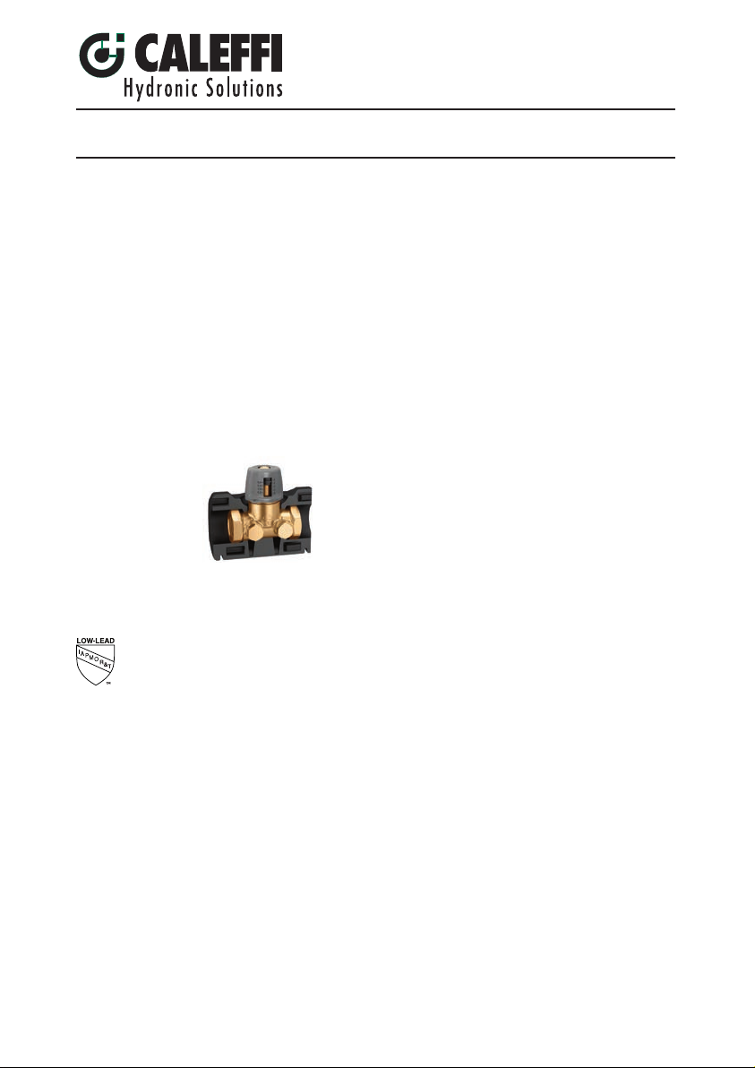
Caleffi 142 series low lead manual balancing valves are used to measure and adjust
the fluid flow rate in hydronic or plumbing circuits. Characterized flow plug which
provides precise system balancing valves and highly accurate flow compared to
other setters with ball valve control. Turning the knob moves a plug within the fluid
stream which varies the flow rate. The flow rate is determined according to the
pressure drop value measured by a differential pressure meter connected to the
pressure test ports, included. The flow rate is directly determined from the pressure
differential created across the two test ports as fluid passes the adjustment plug. The
valve design is variable orifice with pressure ports located upstream and downstream
of the adjustment plug. Compared to fixed orifice designs where both test ports are
located upstream of the adjustment plug, for a given size and flow rate, the variable
orifice design produces a greater differential pressure value. In very low flow rate
applications and with good fluid quality, this larger differential pressure signal can
result in more accurate balancing. A memory stop feature allows the valve to be
closed, and later reopened to the original set position. Insulation shells are available,
purchase separately.
142
Material:
IAPMO R&T.
Suitable fluids: Water and glycol solutions
Max. percentage of glycol: 50%
Maximum working pressure: 232 psi (16 bar)
Working temperature range: 14–250°F (-10–120°C )
Accuracy: ±15%
Number of adjustment turns: 4
Number of regulating positions
Connections: Main: 1/2”–2” NPT female
Valve body pressure test ports: 1/4“ NPT female
Material: EPP
Thickness: ½ inch (15 m m)
Density: 2.8 lb/ft3 (45 kg/m
Thermal conductivity (ISO 2581):
Working t
Reaction to fire (UL 94): Class HBF
Body: DZR low-lead brass
Bonnet: DZR low-lead brass
Control stem: DZR low-lead brass
Hydraulic seals: EPDM
Kn ob: PA6G30
Pressure test ports: DZR low-lead brass body, EPDM seal elements
Reduction of Lead in Drinking Water Act Compliant: 0.25% Max. weighted
average lead content. Reduction of Lead in Drinking Water Act Certified by
emperature range: 23 - 250°F (-5 - 120°C)
142241A 1/2” NPT Female
142251A 3/4” NPT Female
142261A 1” NPT Female
142271A 1 1/4” NPT Female
142281A 1 1/2” NPT Female
142291A 2” NPT Female
Cv
3.4
5.0
7.5
12.9
16.8
22.0
: 8
- at 50°F (10°C): 0.257 BTU·in/hr·ft2·°F (0.037 W/(m·K))
Insulation code:
CBN142241A
CBN142251A
CBN142261A
CBN142271A
CBN142281A
3
)
Page 2
SAFETY INSTRUCTION
This safety alert symbol will be used in this manual to draw attention to safety related instructions.
When used, the safety alert symbol means ATTENTION! BECOME ALERT! YOUR SAFETY
IS INVOLVED! FAILURE TO FOLLOW THESE INSTRUCTIONS MAY RESULT IN A SAFETY
HAZARD.
CAUTION: All work must be performed by qualified personnel trained in the
proper application, installation, and maintenance of systems in accordance
with all applicable codes and ordinances.
CAUTION: Over-tightening and breakage can occur with the use of Teflon
®
pipe joint compounds. Teflon® provides lubricity so that care must be
exercised not to over-tighten joints. Failure to follow these instructions
could result in property damage and /or personal injury.
WARNING: System fluids are under pressure or temperature can be
hazardous. Be sure the pressure has been reduced to zero and the
system temperature is below 100°F (38°C). Failure to follow these
instructions could result in property damage and/or personal injury.
Caleffi shall not be liable for damages resulting from stress corrosion, misapplication or misuse of it products.
Installation
A
PSI
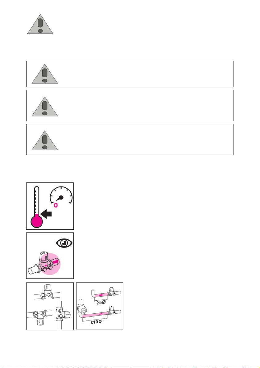
Assembly and disassembly of the valves should always be conducted while the
system is cold and not pressurized (fig. A).
Install according to the flow direction indicated by the arrow on the valve body
(fi g. B).
Can be installed in any orientation (fig. C).
B
In order to ensure measuring accuracy, the balancing valve must be installed by
keeping an upstream straight section of at least five diameters, increased to at
least ten diameters if the nearest device upstream is a pump (fig. D).
C D
Page 3
Operating Principle
The 142 series balancing valve is a
hydraulic device that controls the flow
rate of a fluid. Turning the knob moves a
plug within the fluid stream which varies
the flow rate. The flow rate is determined
according to the pressure drop value
measured by a differentialpressure meter
connected to the pressure test ports.
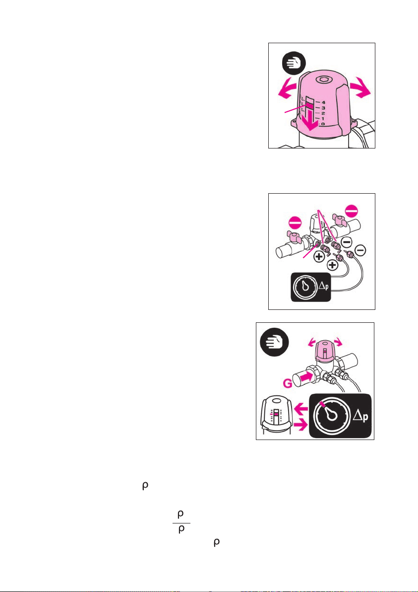
The opening position is indicated by the
numbered indicator (fig. E):
- The turn indicator (1) shows a
regulating scale scale from 0 to 4
(0 closure, 4 complete opening).
Turning the knob manually through
360° causes the indicator to move by
one unit.
E
1
Use of the balancing
valve: setting the
flow rate (fig F-G)
NOTE: the indications + and – on the
drawings refer to the pressure upstream
and downstream of the component
whose pressure differential is to be
measured.
For the connection of the pressure test ports
of the valve (2) with a differential pressure
measuring device (3), use a pair of fittings
with a measuring probe (fi g. F ).
a) As the thermal fluid passes,
measure the Δp of the valve with
any suitable differential pressure
measuring device(fig. G);
b) Using the “Hydraulic
characteristics” sheet (sheet
code 18203 supplied in the
pack), find the flow rate value
that is passing through the valve,
consulting the diagram “Δp-flow
rates” corresponding to the size
of the valve used.
c) Turn the knob and repeat steps a)
and b) until you reach the desired
value.
Correction for liquids of different densities
If using liquids with a density different from water at 70°F (20°C)
≈ 62.4 lb/ft3( ≈ 1 kg/dm3), correct the value of the measured head loss Δp
using the following formula:
F
3
G
4
2
Δp1= Δp
where:
·
Δp1 = reference head loss in (psid(kPa))
Δp = measured head loss in (psid(kPa))
water
= fluid density in lb/ft3 (kg/dm3)
Page 4
Memory Stop on the
142 series balancing
valve
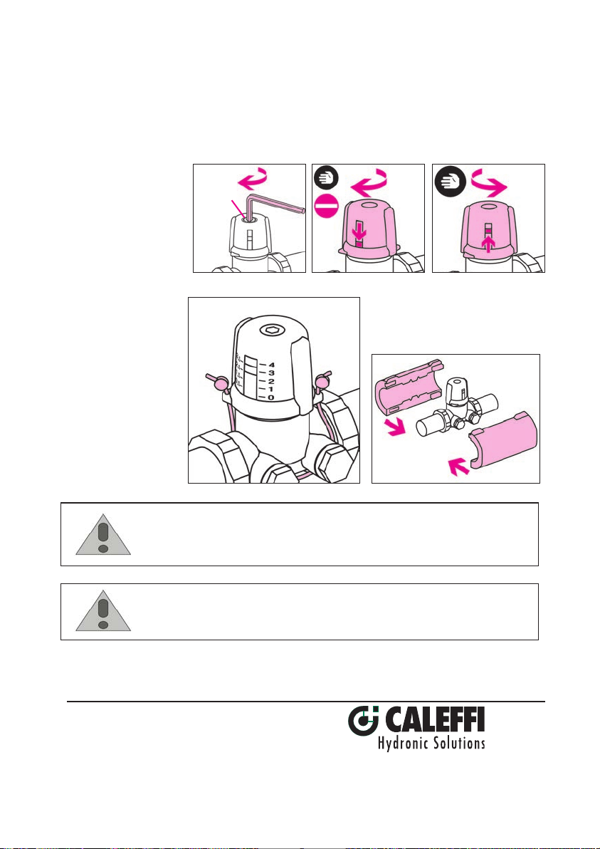
Once you have balanced the flow rate, insert a 2.5 mm hexagonal key into the
hole (5) in the balancing valve and fully turn it clockwise without forcing it. This
sets the valve’s maximum stroke position: if necessary, it is possible to shut off
the balancing valve in the circuit by turning the knob fully clockwise manually. To
restore the valve to its preset position, turn the adjustment knob fully counterclockwise (fig. L).
Locking/sealing the
setting position (fig. M)
CAUTION: If the balancing valve valve is not installed, commissioned and
maintained properly, according to the instructions contained in this
manual, it may not operate correctly and may endanger the user.
H
I L
5
M
Installing Insulation
Join the size-specific insulation shells
on the 142 series balancing valve, sold
under separate code number.
N
CAUTION: Make sure that all the connecting pipework is water tight.
Caleffi North America, Inc.
3883 West Milwaukee Road
Milwaukee, WI 53208
T: 414.238.2360 F: 414.238.2366
2-15-15
Page 5
www.caleffi.com
©
Copyright 2015 Caleffi
18203
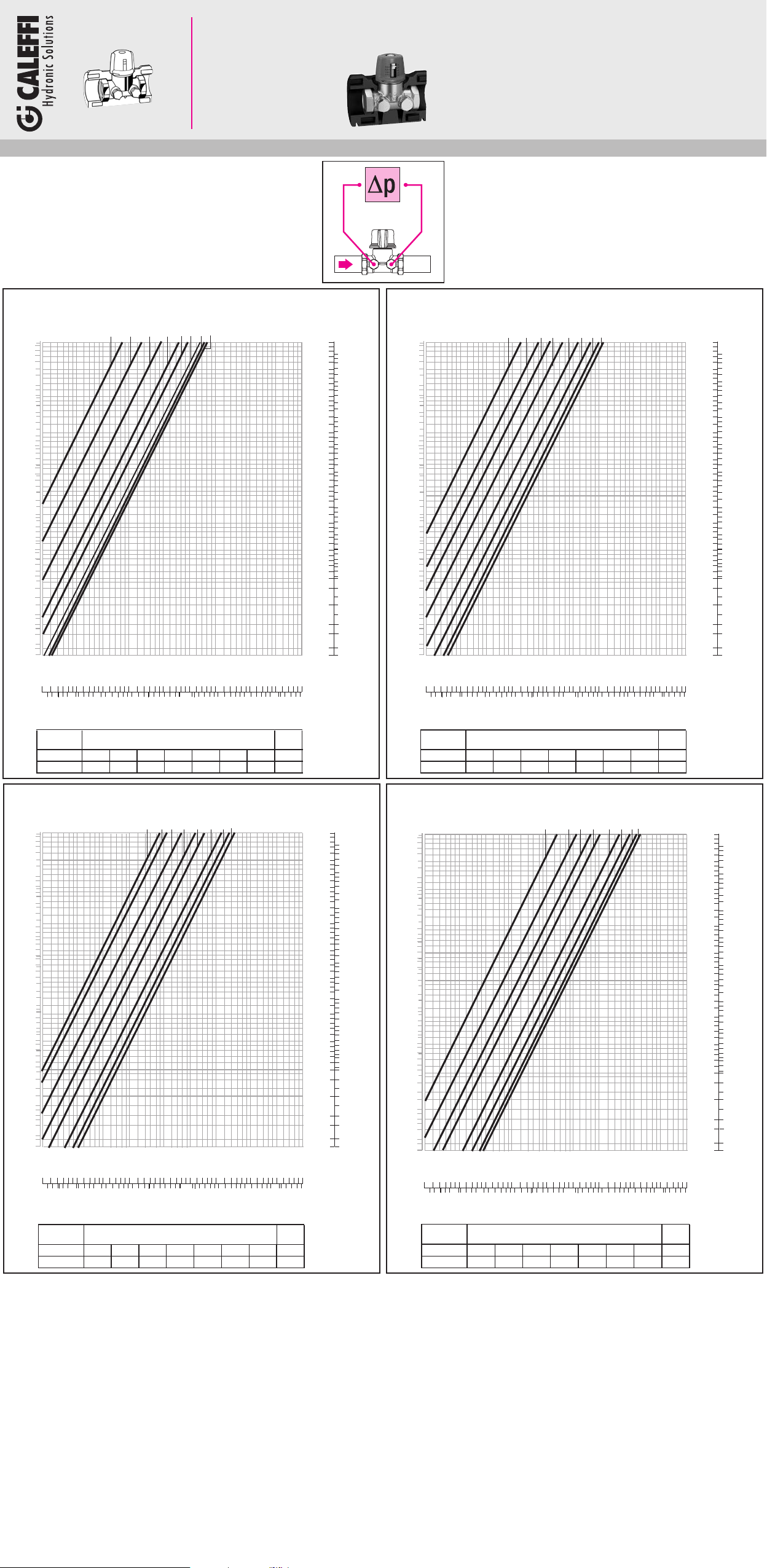
142241A 1/2” NPT Female
142251A 3/4” NPT Female
142261A 1” NPT Female
142271A 1 1/4” NPT Female
142281A 1 1/2” NPT Female
142291A 2” NPT Female
Code 142241A 1/2”
p
Δ
46.00
20.00
10.00
9.00
7.00
5.00
3.00
2.00
1.50
1.00
0.70
0.50
0.30
0.20
0.10
0.05
0.03
0.02
0.015
0.0115
(feet of head)
0.2
.015
Size 1/2"
Cv 0.37 0.63 1.07 1.6 2.13 2.9 3.3 3.4
Position
1
0.5 1 .5 3.5 4
0.3
.02
1
0.5
.03
0.5 1 1.5 2 2.5 3 3.5
.06
2
.10
2 3
5
.30
.20
2.5
10
.50
Position
.70
Code 142251A 3/4”
(psi) (bar)
20
10
5.6
Max
4
7.0
Cv
00
2
12.5
0
2
50100
1.4
2.8
5
4
3
2
1
0.5
0.4
0.3
0.2
0.1
0.05
0.03
0.02
0.01
0.008
0.006
0.005
G
)
gpm
(l/s) (
1.0
0.5
0.4
0.3
0.2
0.1
0.05
0.04
0.03
0.02
0.01
0.005
0.003
0.002
0.001
0.0006
0.0004
0.00035
p
D
46.00
20.00
10.00
9.00
7.00
5.00
3.00
2.00
1.50
1.00
0.70
0.50
0.30
0.20
0.10
0.05
0.03
0.02
0.015
0.0115
(feet of head)
0.2
.015
Size 3/4"
Cv 0.55 0.8 1.2 1.7 2.4 3.7 4.4 5.0
Position
0.3
0.5
.02
.03
0.5 1 1.5 2 2.5 3 3.5
1
.06
.10
2
1
2 3
5
.30
.20
2.5 0.5 1 .5 3.5 4
10
.50
Position
.70
0
2
1.4
50100
2.8
5.6
Max
4
7.0
Cv
(psi) (bar)
20
10
5
4
3
2
1
0.5
0.4
0.3
0.2
0.1
0.05
0.03
0.02
0.01
0.008
0.006
0.005
)
00
2
gpm
G
(l/s) (
12.5
1.0
0.5
0.4
0.3
0.2
0.1
0.05
0.04
0.03
0.02
0.01
0.005
0.003
0.002
0.001
0.0006
0.0004
0.00035
Code 142261A 1”
(feet of head)
p
D
46.00
20.00
10.00
9.00
7.00
5.00
3.00
2.00
1.50
1.00
0.70
0.50
0.30
0.20
0.10
0.05
0.03
0.02
0.015
0.0115
0.3
0.2
.02
.015
Size 1"
Cv 1.0 1.2 1.8 2.6 3.3 5.0 6.5 7.5
Position
1
0.5
.03
.06
0.5 1 1.5 2 2.5 3 3.5
.10
1
2
.20
2 3
5
.30
2.5 0.5 1 .5 3.5 4
10
.70
.50
Position
Code 142271A 1 1/4”
(psi) (bar)
20
10
5.6
7.0
Cv
Max
4
00
2
12.5
0
2
50100
1.4
2.8
5
4
3
2
1
0.5
0.4
0.3
0.2
0.1
0.05
0.03
0.02
0.01
0.008
0.006
0.005
G
)
gpm
(l/s) (
1.0
0.5
0.4
0.3
0.2
0.1
0.05
0.04
0.03
0.02
0.01
0.005
0.003
0.002
0.001
0.0006
0.0004
0.00035
p
D
46.00
20.00
10.00
9.00
7.00
5.00
3.00
2.00
1.50
1.00
0.70
0.50
0.30
0.20
0.10
0.05
0.03
0.02
0.015
0.0115
(feet of head)
0.3
0.2
.02
.015
Size 1 1/4"
Cv 1.5 2.6 3.6 4.5 7.7 10.0 11.8 12.9
Position
1
0.5
.03
0.5 1 1.5 2 2.5 3 3.5
.06
2
.10
.20
.30
1
2 3
2.5 0.5 1 .5 3.5 4
.50
10
.70
0
2
1.4
5
Position
50100
2.8
5.6
7.0
Cv
Max
4
(psi) (bar)
20
10
5
4
3
2
1
0.5
0.4
0.3
0.2
0.1
0.05
0.03
0.02
0.01
0.008
0.006
0.005
)
00
2
gpm
G
(l/s) (
12.5
1.0
0.5
0.4
0.3
0.2
0.1
0.05
0.04
0.03
0.02
0.01
0.005
0.003
0.002
0.001
0.0006
0.0004
0.00035
Page 6
www.caleffi.com
©
Copyright 2015 Caleffi
142241A 1/2” NPT Female
142251A 3/4” NPT Female
142261A 1” NPT Female
142271A 1 1/4” NPT Female
142281A 1 1/2” NPT Female
142291A 2” NPT Female
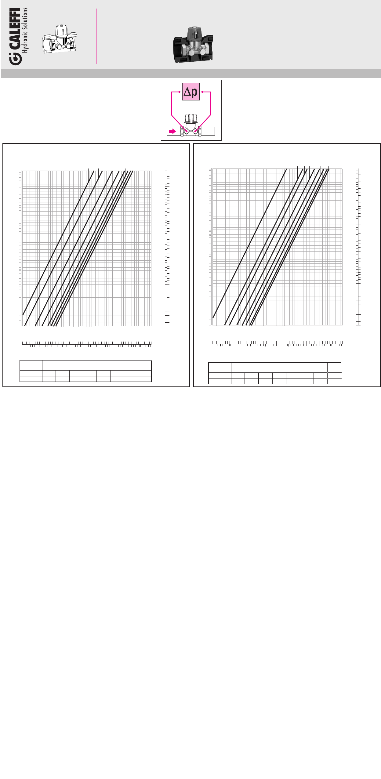
Code 142281A 1 1/2”
(feet of head)
p
D
46.00
20.00
10.00
9.00
7.00
5.00
3.00
2.00
1.50
1.00
0.70
0.50
0.30
0.20
0.10
0.05
0.03
0.02
0.015
0.0115
0.3
0.2
.02
.015
Size 1 1/2"
Cv 2.0 3.3 5.6 8.1 10.9 13.4 14.9 16.8
Position
1
0.5
.03
0.5 1 1.5 2 2.5 3 3.5
.06
2
.10
.20
.30
1
5
.50
Position
Code 142291A 2”
(feet of head)
p
∆
46.00
20.00
10.00
9.00
7.00
5.00
3.00
2.00
1.50
1.00
0.70
0.50
0.30
0.20
0.10
0.05
0.03
0.02
0.015
0.0115
0.3
0.2
.02
.015
Size 2"
Cv 2.3 5.5 7.2 10.2 13.2 17.1 20.0 22.0
Cv
Max
4
7.0
(psi) (bar)
20
10
5
4
3
2
1
0.5
0.4
0.3
0.2
0.1
0.05
0.03
0.02
0.01
0.008
0.006
0.005
)
00
2
gpm
G
(l/s) (
12.5
1.0
0.5
0.4
0.3
0.2
0.1
0.05
0.04
0.03
0.02
0.01
0.005
0.003
0.002
0.001
0.0006
0.0004
0.00035
2 3
2.5 0.5 1 .5 3.5 4
0
10
2
50100
.70
1.4
2.8
5.6
Position
1
0.5
.03
0.5 1 1.5 2 2.5 3 3.5
.06
.10
2
5
.30
.20
.50
Position
10
.70
1
2 3
0
2
1.4
2.5 0.5 1 .5 3.5 4
50100
2.8
5.6
Cv
Max
4
7.0
(psi) (bar)
20
10
5
4
3
2
1
0.5
0.4
0.3
0.2
0.1
0.05
0.03
0.02
0.01
0.008
0.006
0.005
00
2
G
(l/s) (gpm)
12.5
1.0
0.5
0.4
0.3
0.2
0.1
0.05
0.04
0.03
0.02
0.01
0.005
0.003
0.002
0.001
0.0006
0.0004
0.00035
 Loading...