

Page 1
QuickSetter+™ Low-lead
balancing valve with flow meter
132 series
ACCREDITED
ISO 9001 FM 21654
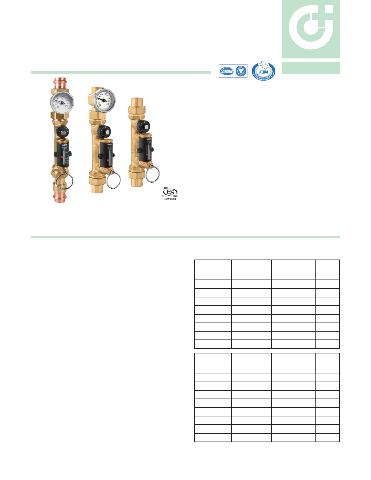
Function
The QuickSetter+™ manual balancing valve contains a built-in flow
meter and sight gauge, negating the need for differential pressure
gauges and reference charts. Circuit balancing is fast, easy and
accurate. Constructed of DZR low-lead brass, QuickSetter+™ is
ideally suited for use in plumbing applications such as hot water
recirculation systems. The built-in check valve protects against circuit
thermo-siphoning. The outlet temperature gauge (optional) verifies the
fluid temperature in the circuit. The flow meter sight gauge is dry (not
exposed to the fluid) thus eliminating the possibility of gauge clouding/
scaling over time. The QuickSetter+™ can also be used in heating
systems.
Product range
132 series Balancing valve with flow meter, includes check valve
and optional outlet temperature gauge.............................................................connections
ISO 9001 No. 0003
½”, ¾”, 1”
sweat union and
CALEFFI
01283/16 NA
Replaces 01283/14 NA
¾”
press union
Technical specications
Materials
Valve
Body: DZR low-lead brass
Ball: stainless steel
Ball control stem: brass, chrome plated
Ball seal seat: PTFE
Control stem guide: PSU
Seals: EPDM
Flow meter
Body and headwork: DZR low-lead brass
Bypass valve stem: stainless steel
Springs: stainless steel
Seals: EPDM
Flow meter float and indicator cover: PSU
NSF/ANSI 372-2011, Drinking Water System Components-Lead Content
Reduction of Lead in Drinking Water Act, California Health and Safety Code
116875 S.3874, Reduction in Drinking Water Act, certified by ICC-ES, file PMG-1360.
Performance
Suitable Fluids: water, glycol solutions
Max. percentage of glycol: 50%
Max. working pressure: 150 psi (10 bar)
Working temperature range: 14 - 230°F (-10–110°C)
Flow rate range unit of measurement: 1/2 - 1 ¾ gpm
2 - 7 gpm
Accuracy: ±10%
Control stem angle of rotation: 90°
Control stem adjustment wrench: 9 mm
Connections
Main connections:
Lay length (press connection): size ¾ inch without gauge: 7
size
½”, ¾”, 1”
¾
inch with gauge: 10
sweat union
¾”
press union
5
/16"
1
/8"
Flow rate ranges
*with temperature gauge.
Code Connection Flow rate (gpm)
132439AFC
132536AFC
132539AFC
132639AFC
132459AFC
132556AFC
132559AFC
132659AFC
Code Connection Flow rate (gpm)
132438AFC*
132537AFC*
132538AFC*
132638AFC*
132458AFC*
132557AFC*
132558AFC*
132658AFC*
½" sweat 0.5 - 1.75 1.0
¾" press 0.5 - 1.75 1.0
¾" sweat 0.5 - 1.75 1.0
1" sweat 0.5 - 1.75 1.0
½" sweat 2.0 - 7.0 6.3
¾" press 2.0 - 7.0 6.3
¾" sweat 2.0 - 7.0 6.3
1" sweat 2.0 - 7.0 6.3
½" sweat 0.5 - 1.75 1.0
¾" press 0.5 - 1.75 1.0
¾" sweat 0.5 - 1.75 1.0
1" sweat 0.5 - 1.75 1.0
½" sweat 2.0 - 7.0 6.3
¾" press 2.0 - 7.0 6.3
¾" sweat 2.0 - 7.0 6.3
1" sweat 2.0 - 7.0 6.3
Fully
open
Cv
Fully
open
Cv
Page 2
4
3
2
1
5
7
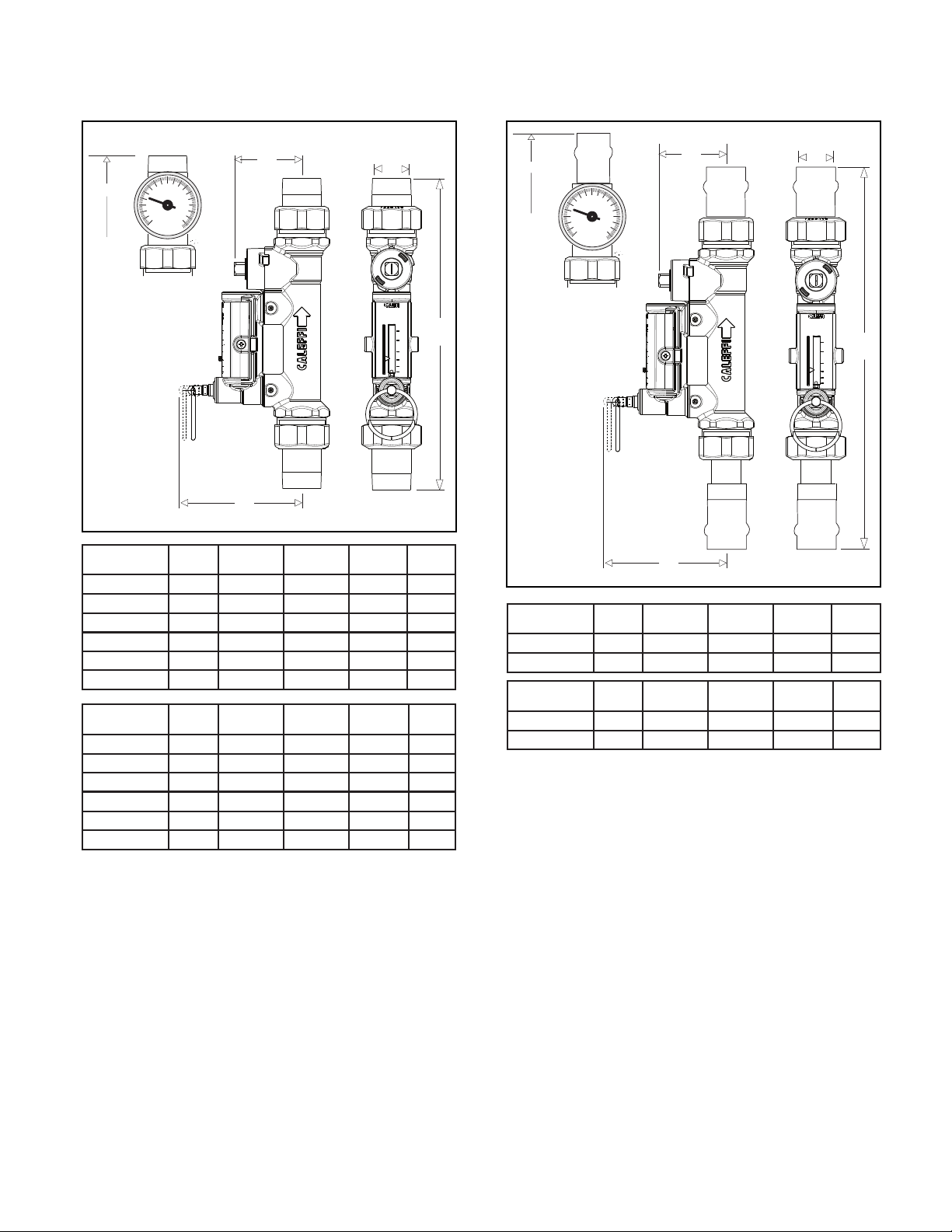
Dimensions
MIX
D
30
50
70
90
110
130
150
170
190
210
˚F
C
1.75
1.50
1.25
1.00
0.75
0.50
P.
A
MAX 150 psi
T.
MAX 230˚F
GPM
1.75
1.50
1.25
1.00
0.75
0.50
B
Code A B C D
132439AFC 1/2" 3 5/16" 1 13/16" 8 3/8" 2.0
132539AFC 3/4" 3 5/16" 1 13/16" 8 7/16" 1.8
132639AFC 1" 3 5/16" 1 13/16" 8 9/16" 2.4
132459AFC 1/2" 3 5/16" 1 13/16" 8 3/8" 2.0
132559AFC 3/4" 3 5/16" 1 13/16" 8 7/16" 1.8
132659AFC 1" 3 5/16" 1 13/16" 8 9/16" 2.4
Code A B C D
132438AFC* 1/2" 3 5/16" 1 13/16" 9 11/16" 2.4
132538AFC* 3/4" 3 5/16" 1 13/16" 9 13/16" 2.2
132638AFC* 1" 3 5/16" 1 13/16" 10 1/8" 2.8
132458AFC* 1/2" 3 5/16" 1 13/16" 9 11/16" 2.4
132558AFC* 3/4" 3 5/16" 1 13/16" 9 13/16" 2.2
132658AFC* 1" 3 5/16" 1 13/16" 10 1/8" 2.8
*with temperature gauge.
Wt
(lb)
Wt
(lb)
MIX
D
110
130
150
90
˚F
170
70
190
50
30
210
D
C
1.75
1.50
1.25
1.00
0.75
0.50
P.
T.
A
MAX 150 psi
MAX 230˚F
GPM
1.75
D
1.50
1.25
1.00
0.75
0.50
B
Code A B C D
132536AFC 3/4" 3 5/16" 1 13/16" 9 7/8" 1.8
132556AFC 3/4" 3 5/16" 1 13/16" 9 7/8" 1.8
Code A B C D
132537AFC* 3/4" 3 5/16" 1 13/16" 12 1/8" 2.2
132557AFC* 3/4" 3 5/16" 1 13/16" 12 1/8" 2.2
*with temperature gauge.
Wt
(lb)
Wt
(lb)
Page 3
3
2
1
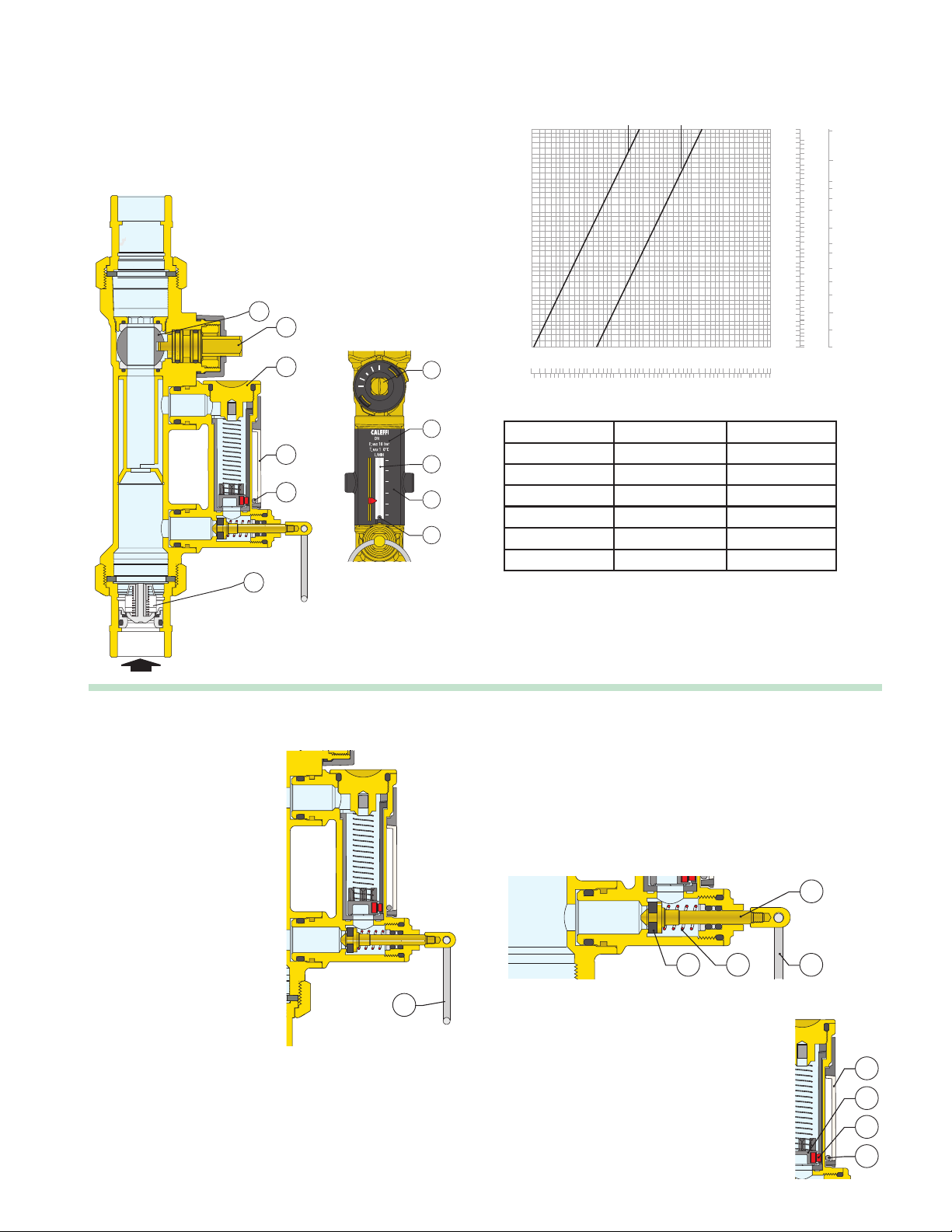
Operating principle
The balancing valve is a hydraulic device that
controls flow rate. The control mechanism is a
ball valve (1), operated by a control stem (2).
The flow rate is manually and properly set by
use of the convenient onboard flow meter (3)
housed in a bypass circuit on the valve body.
This circuit is automatically shut off during
normal operation. The flow rate is indicated
by a metal ball (4) sliding inside a transparent
channel (5) with an integral graduated scale (6).
The QuickSetter+ also includes a inlet check
valve (7) to prevent reverse flow.
1
2
3
2
Hydraulic characteristics at 100% open
p (psi)
∆
20
10
5
4
3
2
1
0.5
0.4 0.4
0.3
0.2
0.1
0.2
0.5
0
5
100
200
1/2 - 1-3/4 gpm
1
2
500
5
1000
2 - 7 gpm
10
2000
2050100
5000
10000
20000
25000
(psi) (bar)
20
10
5
4
3
2
1
0.5
0.3
0.2
0.1
0.050.05
)
00
2
gpm
G
(l/h) (
45000
1.0
0.5
0.4
0.3
0.2
0.1
0.05
0.04
0.03
0.02
0.01
0.005
0.003
(feet of head)
46.00
20.00
10.00
9.00
7.00
5.00
3.00
2.00
1.50
1.00
0.70
0.50
0.30
0.20
0.11
7
Construction details
Flow meter
When activated by pulling the
operating ring (2), the flow rate
is indicated on the flow meter
housed in a bypass circuit on the
valve body. When finished reading
the flow rate, the flow meter is
automatically shut off, isolating
it during normal operation.
Use of a flow meter greatly
simplifies the process of system
balancing since the flow rate can
be measured and controlled at any
time without differential pressure
gauges or reference charts. The
onboard flow meter eliminates the
need to calculate valve settings
during system setup. Additionally,
the unique onboard flow meter
offers unprecedented time and cost
savings by eliminating the long and
difficult procedure of calculating
pre-settings associated with using
traditional balancing devices.
15
5
1
4
3
7
5
6
5
4
6
3
2
4
Connection Flow rate (gpm) Fully open Cv
½" sweat 0.5 - 1.75 1.0
¾" sweat/press 0.5 - 1.75 1.0
1" sweat 0.5 - 1.75 1.0
½" sweat 2.0 - 7.0 6.3
¾" sweat/press 2.0 - 7.0 6.3
1" sweat 2.0 - 7.0 6.3
Flow meter bypass valve
The bypass valve (1) opens and closes the circuit between the flow
meter and the valve. The bypass valve is easily opened by pulling the
operating ring (2), and is automatically closed by the internal return
spring (3) when finished reading the flow rate. The spring and the
EPDM seal (4) provide a reliable seal to isolate the flow meter during
normal operation.
The operating ring (2) material has low thermal conductivity to avoid
burns if the flow meter is opened while hot fluid is passing through the
valve.
1
234
2
Ball/magnet indicator
The metal ball (4) that indicates the flow rate is not
in direct contact with the fluid passing through the
flow meter.
This is an effective and innovative measuring system
in which the ball slides up and down inside a
transparent channel (5) that is isolated from the fluid
flowing through the body of the flow meter. The ball
is moved by a magnet (6) connected to a float (7).
In this way the flow rate indication system remains
perfectly clean and provides reliable readings
over time.
5
7
6
4
Page 4

Complete closing and opening of the valve
765
432
7
6
5
4
3
2
7
6
5
4
3
2
CALEFFI
7
6
5
4
3
2
CALEFFI
765
432
765
432
7
6
5
4
3
2
CALEFFI
7
6
5
4
3
2
CALEFFI
765
432
The valve can be completely closed and opened. A slot on the control
stem indicates the valve position. When the control stem is turned
fully clockwise
perpendicular
(the slot is
to the axis
Completely closed Completely open
of the valve), the valve is
fully closed (A). When the
control stem is turned
fully counter-clockwise
(the slot is parallel to the
axis of the valve), the
valve is fully open (B).
A B
Installation
Install the balancing valve in a location that ensures free access to
the flow meter shutoff valve, control stem and flow rate indicator. To
ensure accurate flow measurement, straight sections of pipe installed
as shown is recommended.
132 series 132 series
Pump
5D
10D
The valve can be installed in any position with respect to the flow
direction shown on the valve body. Additionally, the valve can be
installed either horizontally or vertically.
Flow rate adjustment
The flow rate is adjusted as follows:
A. With the aid of the flow rate indicator (1), mark the desired flow rate.
B. Use the operating ring (2) to open the bypass valve slowly. This
allows fluid to flow through the flow meter (3). The bypass valve is
automatically closed under normal operating conditions.
A B
C. While holding the bypass valve open, use a wrench to turn the valve
control stem (4) to adjust the flow rate slowly. The resulting flow rate
is indicated by the metal ball (5) that slides up and down
inside a
transparent channel (6) marked by a graduated scale in gpm.
C D
765
7
6
5
4
3
2
432
E
765
432
2
3
4
5
6
7
D. Once the flow rate is properly adjusted, release the operating
ring (2) of the bypass valve. The valve will automatically return to
the closed position by means of an internal spring.
E.
A replacement bypass valve stem (7) with operating ring is available
in event it is damaged and inoperable. Order code F19346.
Page 5
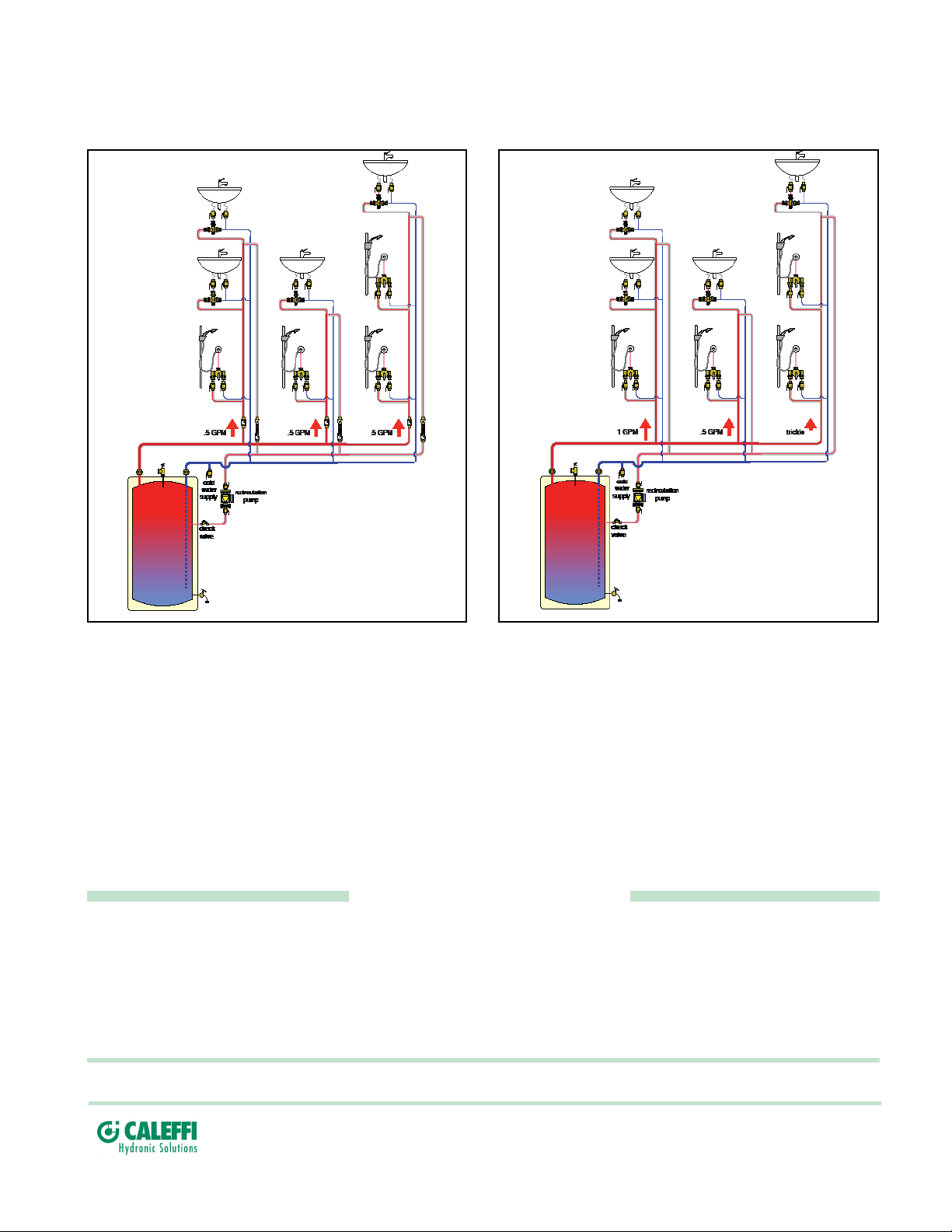
Hot water recirculation
Balanced example
Unbalanced example
Balancing made fast, easy, and accurate with QuickSetter+
Hot water recirculation systems are designed to minimize wait time for hot water to arrive when a fixture is opened. Systems left unbalanced or improperly
balanced result in wasted water down the drain, a costly and environmentally unfriendly situation - not to mention the undesired annoyance placed on
building occupants. The QuickSetter+ takes the guess work and labor out of balancing. With the valve's exclusively designed venturi mechanism, the
installer simply pulls the flow indicator by-pass pin, adjusts the flow to the desired flow rate while viewing the built-in sight gauge, and releases the pin.
Easy, accurate balancing in seconds. No instruments or reference graphs are needed.
SPECIFICATION SUMMARY
132 series
Balancing valve with flow meter. Sweat union connections ½”, ¾", 1". Press union connection ¾". DZR low-lead brass body (<0.25%
Lead content) certified by ICC-ES file PMG-1360. Stainless steel ball. Chrome-plated brass ball control stem. PTFE ball seal seat. PSU
control stem guide. DZR low-lead brass flow meter body and headwork. Stainless steel flow meter bypass valve stem. Stainless steel flow
meter springs. PSU flow meter float and indicator cover. EPDM seals. Provided with inlet flow check valve. Water and glycol solutions.
Maximum percentage of glycol 50%. Maximum working pressure 150 psi (10 bar). Working temperature range 14 to 230 degrees F
(-10 to 110 degrees C). Flow rate range unit of measurement gallons per minute (gpm). Accuracy ± 10%. Control stem angle of rotation
90°. Provide with optional mixed outlet termperature gauge, 30 to 210 degree F scale, 2 inch diameter.
We reserve the right to change our products and their relevant technical data, contained in this publication, at any time and without prior notice.
Calef North America, Inc.
3883 W. Milwaukee Road
Milwaukee, WI 53208
Tel: 414-238-2360 · Fax: 414-238-2366
sales@calef.com · www.calef.com
© Copyright 2016 Calef North America, Inc.
 Loading...