

Page 1
CALEFFI
www.caleffi.com
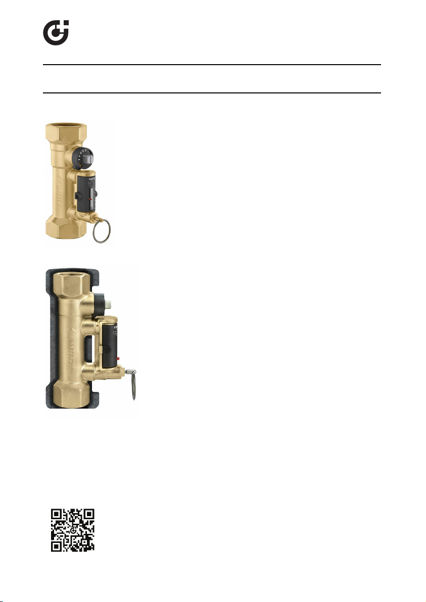
QuickSetter™ Balancing Valve with flow meter
18106.04
© Co pyr igh t 20 1 8 Ca l ef f i
These items are designed for use in
closed hydronic systems. Do not
use in plumbing applications. These
items do not meet the low-lead
plumbing standards of U.S. and
Canada.
Scan to view
·
132 QuickSetter
Installation Tip
132 Series
Function
The balanc ing valve ac c urately controls the flow rate of heating a nd
cooling transfer fluid supplied to fan c oils a nd terminal units; or where
flow ba lanc ing is required in s olar thermal s ys tems . Proper hydronic
system balanc ing ensures the s ys tem operates a c c ording to design
spec ifications, providing s a tisfactory thermal c omfort with low energy
consumption.
The flow meter is housed in a by-pass circuit on the valve body and
can be shut off during norma l operation. The flow meter permits
fas t and eas y circuit ba la nc ing without added differential pressure
gages a nd c harts. T h balanc ing valve comes standa rd with a hot
pre-formed insulation s hell to optimize thermal performanc e for both
hot and chilled water.
Produc t r ange
132 S e ries B alanc ing va lve with flow meter s izes 1/2”, 3/4”,
Technical char act eristics
Va lve
Material: B ody and b all: bra s s
B all control s tem: chrome p lated bras s
B all sea l s eat: PT FE
C ontrol stem guide: PS U
S ea ls : E PDM
F lo w me te r
Material: B ody: bra s s
He adwork: bra s s E N 12 164 C W614N
Valve s tem: chrome p lated bras s
S prings : stainles s s teel
S ea ls : E PDM
Flow meter float a nd indic ator c over: PS U
Pe rforma nc e : Me dium: water, glyc ol s olutions
Flow ra te c orrec tion fac tor: 20% -30% glyc ol s olutions: 0.9
In s ula tio n
Material: closed c ell e xpanded P E -X
Thic knes s : 10 mm
Dens ity: - inner part: 30 kg/m
- outer part: 50 kg/m
Therma l c onductivity (DIN 5 2612): - at 0°C : 0.038 W/(m·K )
C oefficient of re s is tanc e to water vap or (DIN 52615): > 1. 30 0
Working temperature range: 32 - 21 2 F (0–100°C )
R eac tion to fire ( D I N 4102): class B 2
e
1”, 1 1/4”, 1 1/2” a nd 2"
peroxide-cured
Max. perc entage of glycol: 50%
Max. working pres sure: 150 psi (10 bar)
Working tempera ture range : 14 - 230° F (-10–110°C )
Flow ra te ra nge un it of meas urement: gpm
Ac c urac y: ±10%
C ontrol stem angle of rotation: 90°
R equired ope ra ting wrenc h: 1/2”–1 1/4”: 9 mm
Thread ed c onne c tions: 1/2”– 2” F NPT
40%-50% glyc ol solutions: 0.8
1 1/2” and 2 ”: 12 mm
- at 40° C : 0.045 W/(m·K )
3
3
Page 2
SAFETY INST RUCTION
This safety alert symbol will be used in this manual to draw attention to safety related
instructions. When used, the safety alert symbol means ATTENTION! BECOME ALERT!
YOUR SAFETY IS INVOLVED! FAILURE TO FOLLOW THESE INSTRUCTIONS MAY
RESULT IN A SAFETY HAZARD
.
WARNING: This product can expose you to chemicals including lead, which is
known to the State of California to cause cancer and birth defects or other
reproductive harm. For more information go to www.P65Warnings.ca.gov.
CAUTION: All work mus t be pe rforme d by qualified pers onnel trained in the
prope r applic a tion, ins tallation, a nd ma intenanc e of s ys tems in a c c ordance
with all applic a ble c ode s a nd ordinances .
CAUTION: O ver-tightening and brea ka ge c a n oc c ur with the use of Teflon
®
pipe joint c omp ound s . Teflon®provides lubric ity s o that c a re must be
exerc is ed not to over-tighten joints. Failure to follow thes e ins tructions
could res ult in p rope rty dama ge a nd /or pers onal injury.
WARNING: Sys tem fluids a re under pressure or temperature c an be
haz a rdous . Be sure the press ure has been reduc ed to ze ro a nd the
sys tem temp erature is below 1 00 ° F (38°C ) . Failure to follow these
instructions c ould res ult in p roperty d a ma ge a nd/or pers o n a l injury.
C aleffi s hall not be liable for dama ge s res ulting from s tress corros ion, mis application or misus e of it produc ts.
Installation
132 series
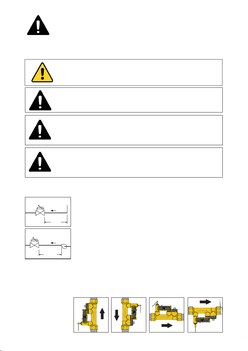
The ba lanc ing valve s , with built-in flow me ter, mus t be installed by
qua lified tec hnic a l pers onnel in ac cordanc e with the instructions given
in this ma nual and with current reg ulations.
C lean the pipe s of a ny deb ris , rus t, welding slag and a ny other
contaminants.
5D
132 series
As in all hydra ulic c irc uits it is important to pa y attention to the
clea nlines s of the entire s ystem.
Pump
For optimal opera tion, a ny air in the me dium must be removed.
In orde r to ens ure mea s uring ac c urac y, the bala
ncing va lves with flow
meter mus t be installed b y keeping a s traight s ec tion a bove them at
10D
leas t a s long a s five diameters , inc reased to a t le ast ten diameters if
the nea rest device ups tream is a pump.
The valves must be installed so that:
- the direc tion of the flow agrees with that of the a rrow on the
valve body.
- there is easy ac c es s to the flow meter valve , c ontrol s tem and dial
with the c a libra tion ad justment ra nge.
The valves can be fitted on either vertica l or horiz ontal pipes.
6
5
7
2
3
4
5
6
7
6
5
4
3
2
7
432
7
2
654
3
Page 3
Flow rate
adjustment
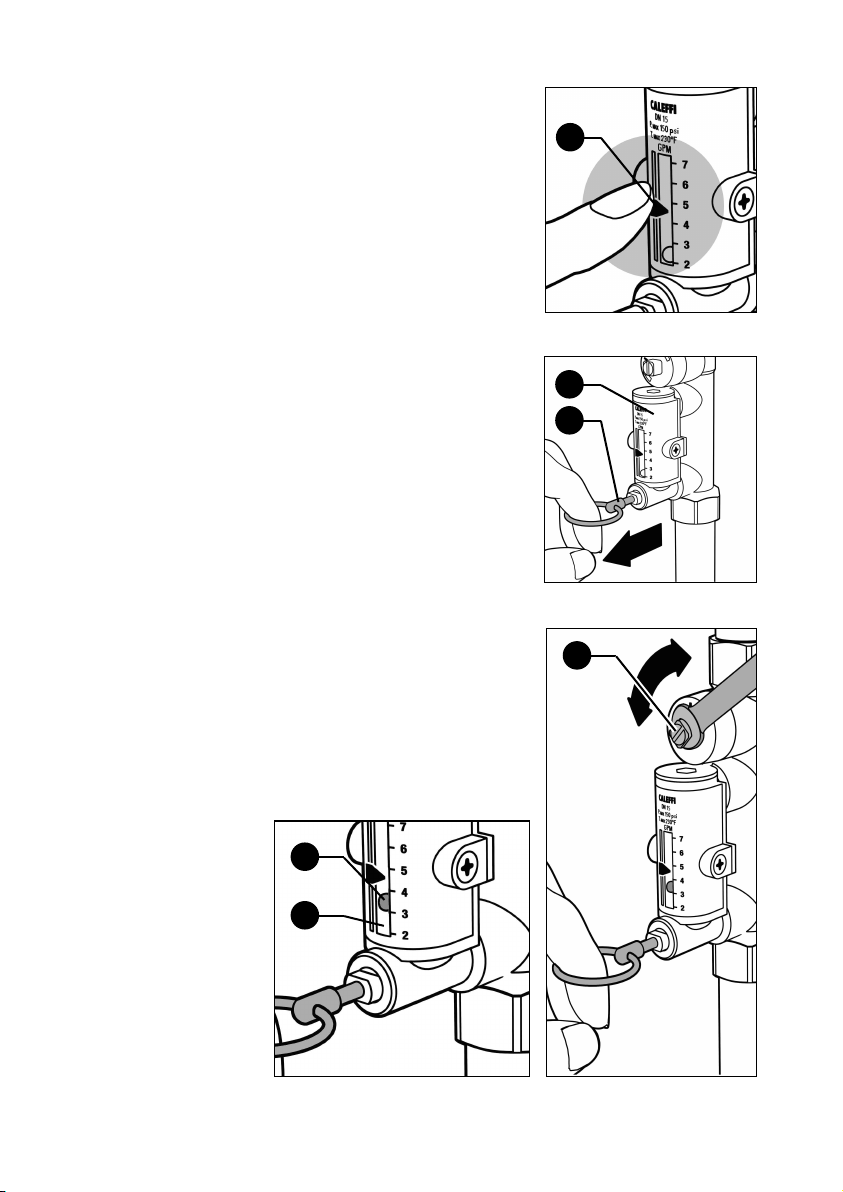
The flow rate is adjusted by carrying
out the following operations:
A. With the aid of the indicator (1),
mark the reference flow rate on
which the valve is to be set.
B. Use the ring (2) to slowly open the
flow meter bypass valve that shuts
off the flow of medium in the flow
meter (3) under normal operating
conditions.
C. Keeping the flow meter bypass
valve open, apply a wrench (9 mm
for 1/2" to 1 1/4" sizes; 12 mm for
1 1/2" and 2" sizes) to the balancing
valve control stem (4) to slowly
adjust the flow rate, which is
indicated by a metal ball (5) that
runs inside a transparent cylinder
(6) alongside which there is a
graduated scale in GPM.
1
3
2
4
5
6
Page 4
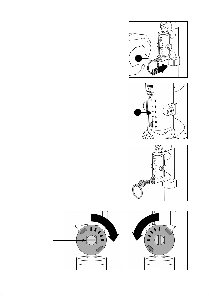
D. After completing the
balancing, release the ring (2)
of the flow meter bypass
valve, which will automatically
go back into the closed
position.
E. On completing the
adjustment, the indicator (1)
can be used to keep the
setting in memory, in case
checks need to be made
over time.
F. A replacement flow meter
bypass valve stem with
operating ring is available in
the event it is damaged and
inoperable.
Order code F19346. See
page 6 for replacement
instructions.
2
1
Complete
closing/opening
of valve
Balancing valve
control stem
Complete opening of valveComplete closing of valve
Page 5
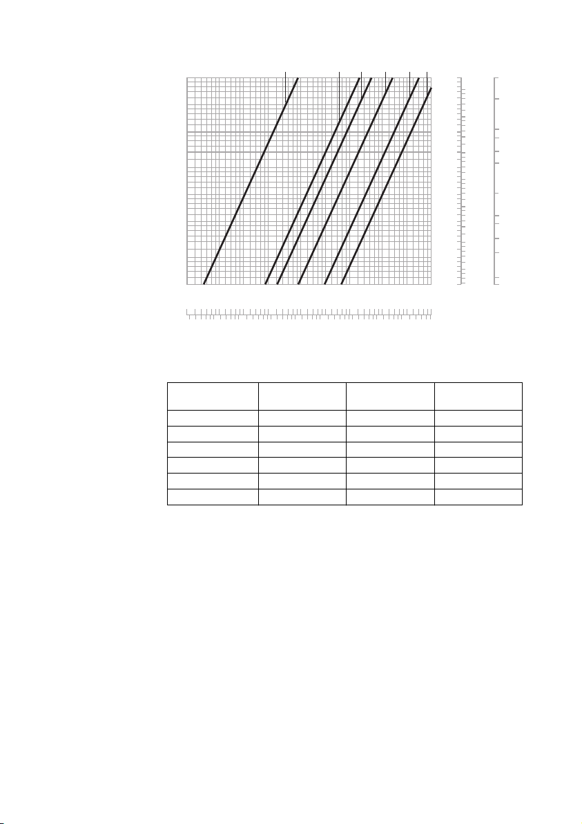
Hydraulic
100
0
.1
1
0
.2
0.3
0.5
200
500
∆
p
(psi)
G
(l/h) (
gpm
)
10
2
3
5
20
0
.1
1
0
.2
0.3
0.5
(
psi) (bar) (feet of head)
10
2
3
5
20
0.01
0.1
0.02
0
.03
0.05
1.0
0.2
0.3
0.5
4
0.4 0.4
4
0.04
0
.4
1000
2000
5000
1
0.2
0.5
2
5
10
2
0
50100
2
00
5
0
1/2”
3/4”
1”
1 1/4”
1 1/2”
2”
46.20
2
3.10
11.55
9.24
6.93
4.62
2.31
1.16
0.924
0.693
0.462
0.231
characteristics
at 100% open
Code Connection Flow rate (GPM) Cv
132432A 1/2” NPT 1/2 – 1 3/4 1.0
132552A 3/4” NPT 2.0 – 7.0 6.3
132662A 1” NPT 3.0 – 10.0 8.3
132772A 1 1/4” NPT 5.0 – 19.0 15.2
132882A 1 1/2” NPT 8.0 – 32.0 32.3
132992A 2” NPT 12.0 – 50.0 53.7
Page 6
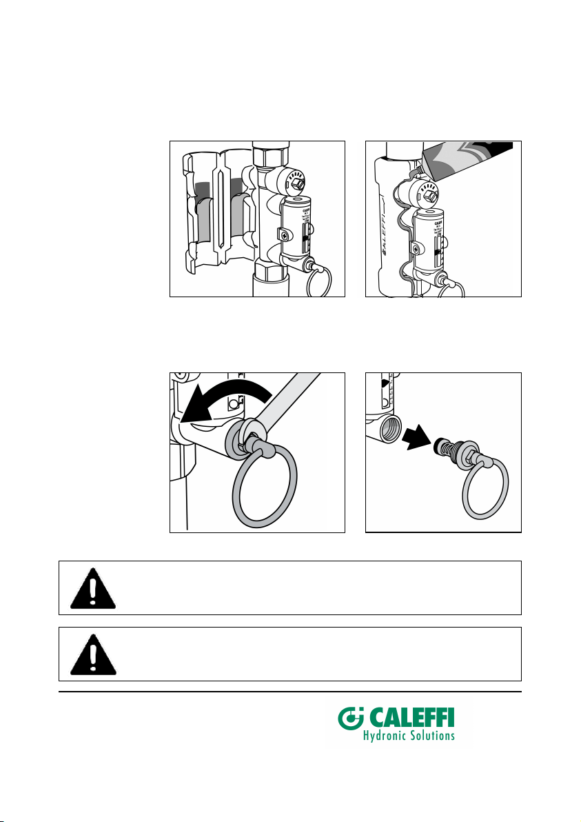
Procedure for
installation and
insulation
assembly
Procedure for
replacing bypass
valve stem with
operating ring
1.
Remove the protective strip from the adhesive
insulation shells.
2.
If the balancing valve with flow meter is used with chilled water, spread a
thin layer of sealant on the edge of the insulation and wait until the solvent
evaporates (10 minutes approx.) and then re-close it.
1.
Remove bypass valve assembly with an 8 mm wrench.
2.
Install replacement bypass valve assembly, code F19346, using locktight
to seal the threads.
surface. Re-close the
CAUTION: If the balancing valve valve is not installed, commissioned and
maintained properly, according to the instructions contained in this
manual, it may not operate correctly and may endanger the user.
CAUTION: Make sure that all the connecting pipework is water tight.
7-19-18
Caleffi North America, Inc.
3883 West Milwaukee Road
Milwaukee, WI 53208
T: 414.238.2360 F: 414.238.2366
 Loading...