

Page 1
www.caleffi.com
Misuratore elettronico di portata
per collegamento sensore ad effetto Vortex
88163.01
© Co py rig ht 2 011 Cal ef f i
MANUALE DI INSTALLAZIONE E MESSA IN SERVIZIO
INDICE
Funzione
Avvertenze
Gamma prodotti
Composizione confezione
Serie 130
1
2
Funzione
Il misuratore di portata consente di effettuare la
misura della portata istantanea all'interno di un
tubo: in particolare lo strumento è stato realizzato
per essere abbinato a sensori da inserire in
valvole a sfera Caleffi.
I sensori abbinati al misuratore utilizzano un
effetto chiamato “Coda dei vortici di von
Kàrmàn”, grazie al quale è possibile determinare
la velocità media del fluido circolante. Lo
strumento di misura possiede le informazioni
relative alla superficie di passaggio del fluido e i
fattori di conversione: in tale modo è possibile
ricavare il valore della portata istantanea.
Il dispositivo possiede un’impugnatura
ergonomica anti scivolo ed è stato concepito per
essere semplice da utilizzare e configurare.
Caratteristiche tecniche
Interfaccia utente
Accensione e misura
Navigazione dei menu e configurazione dello strumento
Carica batterie
Consigli per l’utilizzo
Impostazioni utente
3
4
5
6
1
Page 2
AVVERTENZE
Le seguenti istruzioni devono essere lette e comprese prima dell’utilizzo del misuratore.
Il simbolo di sicurezza viene usato in questo manuale per attirare l’attenzione sulle istruzioni relative
alla sicurezza. Il simbolo ha il seguente significato:
ATTENZIONE! LA TUA SICUREZZA È COINVOLTA. UNA MANCANZA NEL SEGUIRE
QUESTE ISTRUZIONI PUÒ ORIGINARE PERICOLO.
- Il dispositivo è destinato ad essere utilizzato esclusivamente da personale qualificato, rispettando le precauzioni
indicate nel presente documento e le regole di buon senso. Il dispositivo non è adatto all'utilizzo da parte di
bambini o personale non adeguatamente preparato.
- Non accendere il dispositivo in luoghi a rischio di incendio o di esplosione.
- Non accendere il dispositivo in aereo o in zone con pericolo di interferenze elettromagnetiche.
- Non collegare direttamente il dispositivo alla rete elettrica: per la carica della batteria del dispositivo servirsi
escusivamente del trasformatore fornito in confezione.
- Non collegare l'apparecchio a superfici con tensioni elevate e pericolose.
- Non mantenere in carica l'apparecchio per un tempo superiore a 14 ore.
- Durante la carica non posizionare l'apparecchio su superfici facilmente infiammabili.
- Non bagnare e non immergere lo strumento in acqua o in altri liquidi.
- Il sensore non è idoneo all'utilizzo con sostanze potenzialmente pericolose per l'uomo come acidi, liquidi
fortemente basici, liquidi infiammabili, tossici o esplosivi.
- Utilizzare esclusivamente sensori Caleffi approvati.
- Non aprire il misuratore o il sensore: in caso di manomissione decadrà automaticamente la garanzia ed il prodotto
potrebbe non funzionare correttamente. La Caleffi inoltre non sarà responsabile di eventuali malfunzionamenti o
danni direttamente o indirettamente causati dall’utilizzo dello strumento.
- Caleffi non è responsabile per danni diretti o indiretti a persone o cose causati dall’utilizzo non corretto, non
previsto o non consentito dello strumento.
- Il prodotto a termine del suo ciclo vita deve essere smaltito seguendo le norme vigenti relative allo smaltimento
di un rifiuto elettronico e non può essere trattato come un semplice rifiuto urbano. Il prodotto è costituito da parti
non biodegradabili e sostanze che possono inquinare l’ambiente circostante se non opportunamente smaltite. Il
prodotto deve essere smaltito presso centri di raccolta idonei allo smaltimento di prodotti contenenti componenti
elettronici.
Gamma prodotti
Cod. 130010 Misuratore elettronico di portata per collegamento sensore ad effetto Vortex
Composizione confezione
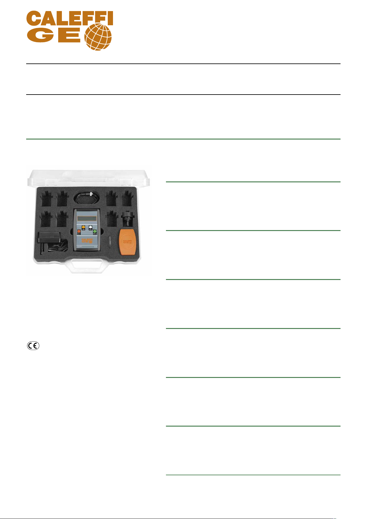
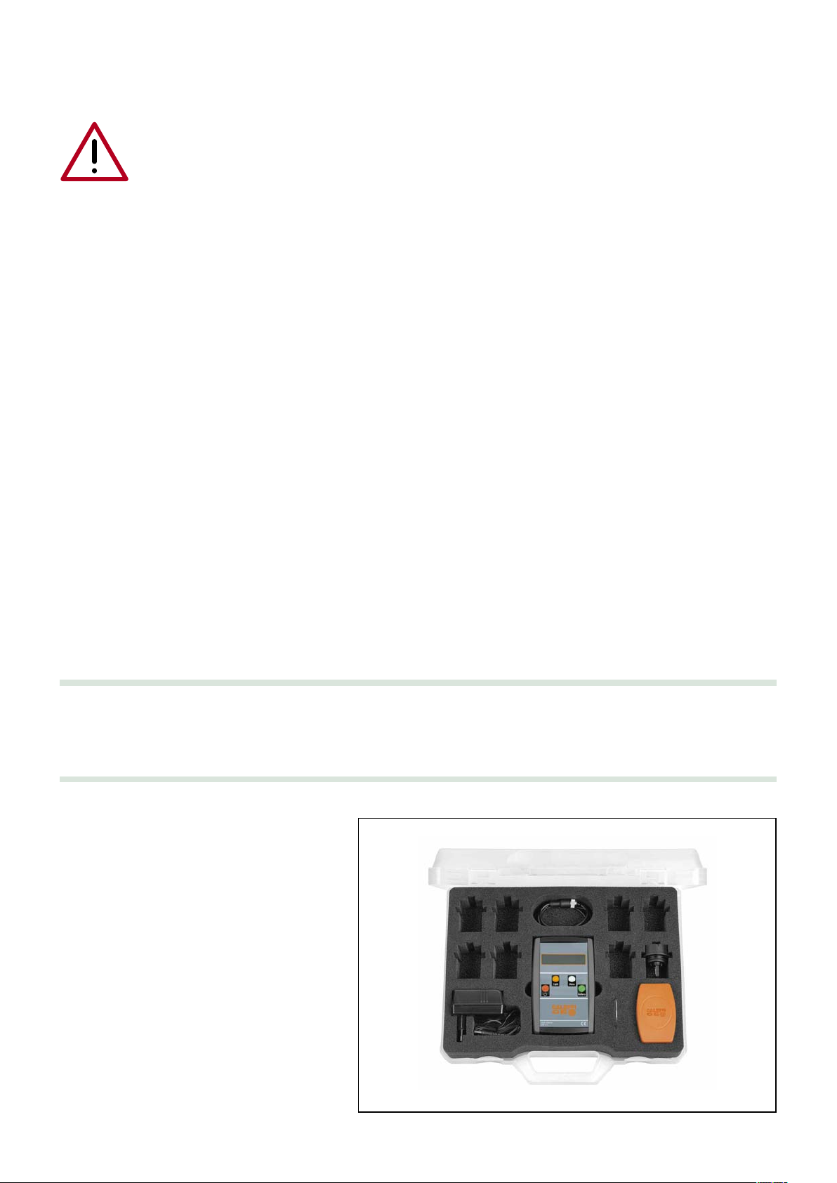
La confezione comprende:
Misuratore elettronico di portata per
collegamento sensore ad effetto Vortex
• Valigetta di contenimento.
• Alimentatore.
• Leva di comando.
• Sensore di misura ad effetto Vortex.
• Cavo di collegamento.
• Anello di fissaggio sensore.
• Fermo
2
Page 3
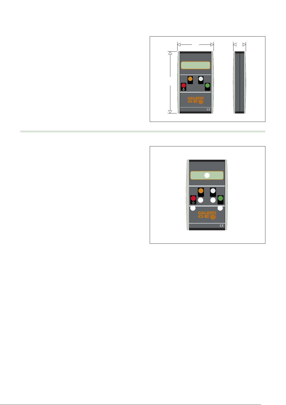
Caratteristiche tecniche
96
155
29
Battery
MenuLight
Cod. 130010
IP 44
Battery
MenuLight
Cod. 130010
IP 44
Misuratore
Display: alfanumerico con retroilluminazione bianca
Portata minima: 300 l/h
Portata massima: 1400 l/h
Errore massimo: ±10%
Unità di misura utilizzabili: l/h, l/min, GPM
Liquidi utilizzabili: acqua, soluzioni glicolate fino a 50%
Peso: 220 g
Alimentazione: batteria interna 9V NiMh
Carica batterie
Tensione di alimentazione: 230 V~ 50 Hz
Potenza assorbita (MAX): 6 W
Dimensioni
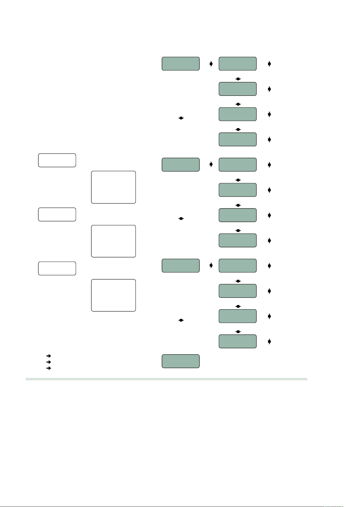
Interfaccia utente
➮
➅
1) Display con l’indicazione della portata
2) Pulsante di accensione spegnimento “ON/OFF” ●
3) Pulsante di “Light” ●
4) Pulsante di attivazione del “Menu”
5) Pulsante “Battery” ●
6) Presa per collegamento sensore
7) Presa per collegamento carica batterie
Il Display LCD permette di visualizzare la portata durante la misura,
i menù di configurazione e le altre informazioni necessarie per il
corretto utilizzo dello strumento.
Per accendere il misuratore è necessario tenere premuto il pulsante
di accensione ●fino alla comparsa delle scritte sul display. Per
spegnere il dispositivo è necessario tenere premuto il pulsante ●
fino alla scomparsa di tutte le scritte presenti sul display. Non
premendo alcun pulsante il dispositivo si spegne automaticamente
dopo 4 minuti, anche con sensore collegato: in questo modo è
possibile garantire una maggior durata della carica della batteria
interna allo strumento stesso.
Per ridurre il consumo della batteria è stato predisposto un sistema che consente di spegnere il misuratore dopo l'inserimento o il
disinserimento del cavo di collegamento al sensore Vortex.
La pressione del pulsante “Light” ●attiva o disattiva la retroilluminazione del display di lettura per consentire la lettura dello strumento anche
in un ambiente privo di illuminazione. Dopo 1 minuto la retroilluminazione viene disattivata automaticamente per prolungare la durata di carica
della batteria.
La pressione del pulsante○consente di accedere al menu di configurazione e muoversi al suo interno. Uscendo dalla pagina dei Menù si
torna alla visualizzazione della misura.
Dalla schermata di misura, premendo il pulsante ●viene visualizzato lo stato di carica della batteria interna del dispositivo. Per ritornare alla
schermata di misura è necessario premere nuovamente il pulsante ●.
○
➁
➀
➂ ➃
➆
➄
➭
Accensione e misura
All’accensione del dispositivo viene visualizzata una stringa identificativa.
Una volta acceso lo strumento tramite il pulsante “ON/OFF”, è sufficiente premere il pulsante “Menu” o “Battery” per passare alla modalità “Misura”
in cui sul display compare la portata letta dal sensore. Per effettuare una misura è necessario che il sensore sia collegato allo strumento.
Durante la lettura sul display compare:
Viene indicato il simbolo di portata seguito dal valore numerico, dall’unità di misura tra parentesi quadre. L’indicazione del tipo di fluido avviene
nella seconda riga del display.
Se la portata misurata risulta eccessivamente bassa (inferiore a 300 l/h), se il sensore non è stato collegato o inserito correttamente lo strumento
non è in grado di effettuare la misura in modo corretto e la portata indicata è 0.
Q = 610 [l/h]
3
Page 4
Navigazione nei menu e configurazione dello
strumento
La navigazione nel menù avviene tramite il pulsante
“Menu”
successiva, mentre il pulsante “Battery” ●permette di
entrare nel sottomenù. Per uscire dal menù è
necessario premere il pulsante “Battery” ●sulla voce
“Exit”: a qualunque livello dei menù l’uscita riporta il
dispositivo nello stato di misura.
La pressione del pulsante di accensione ●permette di
uscire, di ritornare al menù precedente o alla modalità
di misura.
“Menu”
○
●“Battery”
●“ON/OFF”
La struttura dei menù è quella riportata di seguito.
che consente di passare alla voce
○
ATTENZIONE: se la modifica di un parametro di configurazione
viene fatta durante una misura è necessario attendere alcuni
secondi perché l'indicazione dello strumento divenga corretta.
MENU’
UNITA’/UNIT
●
UNITA’/UNIT
> l/h
modalità misura
●
○
UNITA’/UNIT
- l/min
modalità misura
●
○
○
UNITA’/UNIT
- GPM
modalità misura
●
○
UNITA’/UNIT
EXIT
modalità misura
●
MENU’
UNITA’/UNIT
UNITA’/UNIT
> l/h
- l/min
- GPM
EXIT
MENU’
LIQUIDO/LIQUID
LIQUIDO/LIQUID
> Acqua/Water
- 30% di glicole
- 50% di glicole
EXIT
MENU’
VERSION
CALEFFI S.p.a
I° 001
SW 0/10 HW 0/10
Reset
EXIT
Durante la navigazione nei menu, le voci non attive
sono indicate con un meno (“-”) mentre quelle attive
con un maggiore (“>”). Si consideri il seguente
esempio di unità di misura scelta pari a “l/min”:
UNITA’ DI MISURA
“Battery” - l/h
“Menu” > l/min
“Menu” - GPM
MENU’
LIQUIDO/LIQUID
○
MENU’
VERSION
○
MODALITÀ
DI MISURA
●
●
LIQUIDO/LIQUID
> Acqua/Water
○
LIQUIDO/LIQUID
- G30%
○
LIQUIDO/LIQUID
- G50%
○
LIQUIDO/LIQUID
EXIT
CALEFFI S.p.a
I° 001
○
CALEFFI S.p.a
SW 0/10 HW 0/10
○
CALEFFI S.p.a
Reset
○
CALEFFI S.p.a
EXIT
modalità misura
●
modalità misura
●
modalità misura
●
modalità misura
●
modalità misura
●
modalità misura
●
modalità misura
●
modalità misura
●
Carica batterie
Per il caricamento della batteria interna viene utilizzato un caricabatteria con le seguenti caratteristiche:
- tensione di alimentazione: 18 V (dc)
- corrente massima assorbita dal dispositivo in carica (@18 V): 50 mA
- corrente media assorbita dal dispositivo in carica (@18 V): 20 mA
- potenza massima dell’alimentatore: 6 W
- collegamento: jack audio 3,5 mm
- batteria di riferimento: ricaricabile NiMh 9 V 225 mAh
La carica della batteria viene espressa in % tra 100% e 0%: quando la carica della batteria risulta essere eccessivamente bassa
è necessario effettuare la ricarica del dispositivo.
Il misuratore è in grado di funzionare correttamente anche in fase di carica: è quindi possibile utilizzare lo strumento mentre è
collegato al caricabatterie.
Durante il caricamento premendo il pulsante “Battery” viene riportata l’indicazione “BATTERY CHARGE”.
4
Page 5
Consigli per l’utilizzo
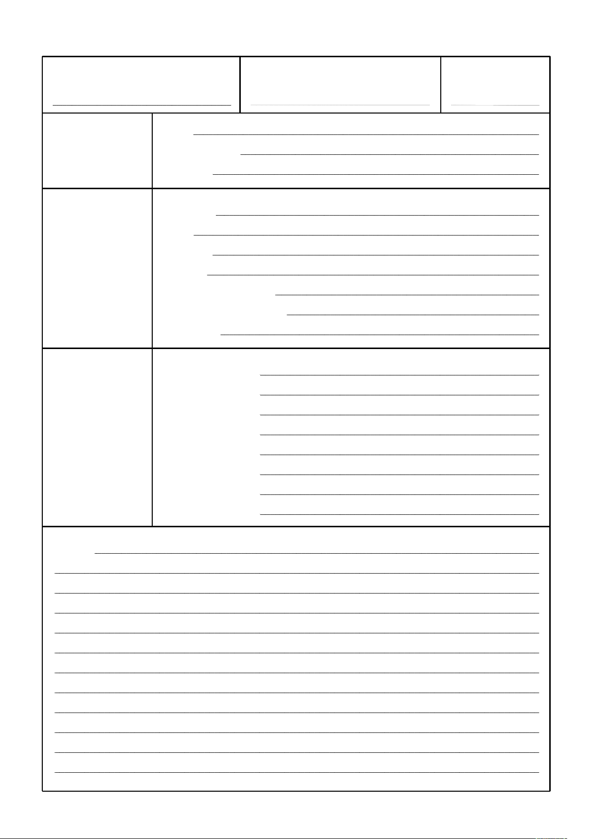
5. Accendere lo strumento e passare in modalità di misura.
Prima di effettuare una serie di misure è consigliabile
controllare le impostazioni dello strumento, ponendo
particolare attenzione alla tipologia di fluido utilizzato.
Si ricorda che tutte le configurazioni possono essere
effettuate anche senza collegare il sensore. Se la modifica
viene fatta durante la misura è necessario attendere qualche
secondo perché l'indicazione dello strumento si stabilizzi.
Se lo strumento viene acceso dopo averlo collegato al sensore
impiega meno tempo a visualizzare la portata corretta.
Per effettuare correttamente la misura sfogare l’aria
dall’impianto e utilizzare appositi filtri per evitare la presenza
di fanghi.
Eventuali variazioni nell’indicazione di portata possono
essere legati alla presenza di aria nell’impianto.
Maneggiare con cura e porre attenzione durante la
regolazione e manovra delle valvole per non causare
fuoriuscite eccessive di liquido dall’impianto.
Lo strumento di misura e il sensore sono dispositivi elettronici
che possono subire danni in caso di caduta, colpi o utilizzo
improprio.
Al termine di questo documento è presente un modulo che può
essere fotocopiato e lasciato a disposizione per controlli futuri.
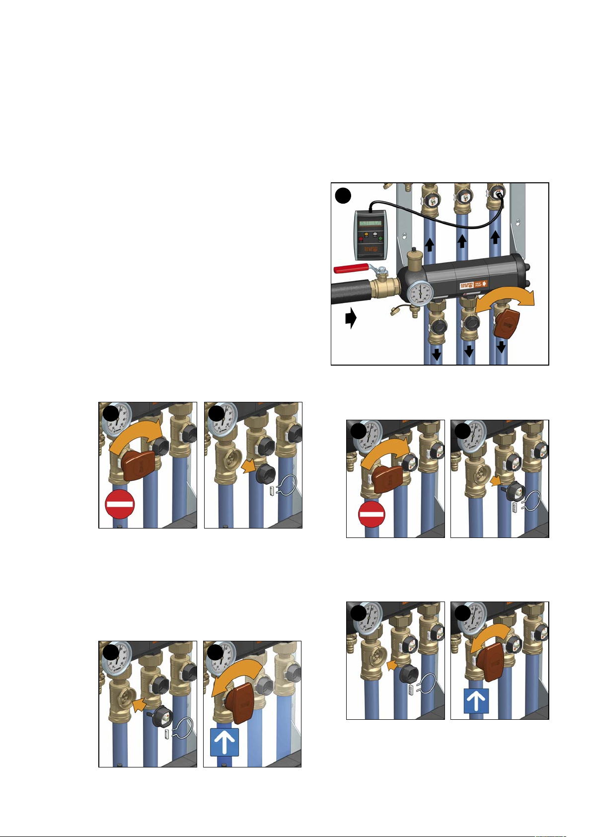
Come effettuare una misura
1. Chiudere la valvola in cui deve essere inserito il sensore,
badando che tutte le altre valvole siano aperte.
Attendere alcuni secondi che la portata nel circuito si stabilizzi
e che l’eventuale aria presente nell’impianto venga espulsa.
Regolare lentamente la valvola di intercettazione opposta
e attendere che il sistema si stabilizzi al valore desiderato
(se il bilanciamento viene ripetuto più volte per la
presenza di diversi rami, non è richiesta, soprattutto nelle
prime manovre, un’eccessiva precisione).
Una volta raggiunta la portata desiderata scollegare il
cavo dal sensore.
5
2. Rimuovere il fermo, l’anello e il tappo (il tappo può essere
rimosso solo se la valvola risulta correttamente chiusa).
1
3. Inserire il tappo porta sensore, l’anello di blocco e il fermo
verificandone il corretto posizionamento, in caso di
montaggio orizzontale della valvola utilizzare l’apposita
vite di scarico posta sul retro per facilitare l’inserimento
del tappo porta sensore.
4. Aprire completamente la valvola con il sensore
utilizzando l’apposita manopola e successivamente
collegare il cavo al sensore e allo strumento.
2
3 4
6. Chiudere la valvola del tappo porta sensore con
l’apposita maniglia.
7. Rimuovere il fermo anello e il tappo porta sensore.
6
8. Inserire il tappo cieco nella valvola a sfera e fissare
l’anello elastico di tenuta con il fermo.
9. Riaprire completamente la valvola utilizzando l’apposita
manopola.
7
8 9
La valvola a sfera utilizzata per la regolazione non ha un
comportamento lineare e, specie per portate basse, la
regolazione può essere difficoltosa poiché a piccole
variazioni della valvola a sfera corrispondono ingenti
variazioni nella portata. Ripetere l’operazione per tutte le
altre derivazioni del collettore.
5
Page 6
Nome: Luogo: Data:
Ditta:
Installatore: Responsabile:
Telefono:
Impianto:
Tipo:
Potenza:
Dati Portata:
impianto Temperature estive:
Temperature invernali:
Fluido / %
Portata circuito 1:
Portata circuito 2:
Portata circuito 3:
Dati Portata circuito 4:
collettore Portata circuito 5:
Portata circuito 6:
Portata circuito 7:
Portata circuito 8:
Note:
6
Page 7

www.caleffi.co m
Electronic flow rate meter for connection to Vortex effect sensor
Co py rig ht 201 3 C ale ffi
©
130 series
INSTALLATION AND COMMISSIONING MANUAL
CONTENTS
88163.01EN
Function
The flow rate meter measures the instantaneous
flow rate inside a pipe: in particular, the device
was designed to work with sensors to be installed
in Caleffi ball valves.
Sensors working with the meter use the “Kármán
vortex street effect”, thanks to which the average
speed of a medium can be measured. The flow
meter contains data regarding the flowing surface
of the medium and conversion factors needed to
be able to calculate the instantaneous flow rate.
The device has an easy-grip and non-slip handle,
and was designed to make it easy to use and
configure.
Function
Warnings
Product range
Package contents
Technical specifications
User Interface
Switching on and taking measurements
Browsing menus and device configuration
Battery charger
Recommendations for use
User settings
1
2
3
4
5
6
1
Page 8

WARNINGS
The following instructions must be read and understood before installing the meter.
The safety symbol is used in this manual to draw attention to the respective safety
instructions. The meaning of this symbol is as follows:
CAUTION! YOUR SAFETY IS INVOLVED! FAILURE TO FOLLOW THESE INSTRUCTIONS MAY
RESULT IN INJURY.
- The device is intended for use only by expert personnel and in accordance with the precautions laid down in this
document and in line with established good practice. The device is not suitable for use by children or untrained
ersonnel.
p
Do not switch the device on in places where there is a risk of fire or explosion.
-
- Do not switch the device on in airplanes or areas where there is a danger of electromagnetic interference.
- Do not connect the device straight to an electric supply network: use the transformer provided to charge the battery
- Do not connect the device to surfaces with high or dangerous voltages.
- Do not charge the device for more than 14 hours.
- Do not charge the device on easily flammable surfaces.
- Do not wet or immerse the device in water or other liquids.
- The sensor is not suitable for use with substances which could be hazardous to humans, such as acids, highly
basic liquids, and toxic, flammable or explosive liquids.
- Only use Caleffi-approved sensors.
- Do not open the flow meter or sensor: if tampered with, the warranty automatically ceases to have effect and the
device may no longer function properly. Furthermore, Caleffi shall not be liable for any malfunction or damage
resulting, either directly or indirectly, from use of the device.
- Caleffi shall not be liable for any damage caused to people or things, either directly or indirectly, as a result of
incorrect, unintended or improper use of the device.
- At the end of its life cycle, the device must be disposed of in accordance with applicable legislation regarding
the disposal of electronic waste and must not be treated as simple urban waste. The device has nonbiodegradable parts and substances which could pollute the surrounding environment if not disposed of
properly. The device must be disposed of in approved waste collection centers able to dispose of products
containing electronic components.
Product range
Code 130010 Electronic flow rate meter for connection to Vortex effect sensor
Package contents
The package contains:
Electronic flow rate meter for connection to
Vortex effect sensor
• Device case.
• Electric supply unit.
• Control lever.
• Vortex-effect measuring sensor.
• Connection cable.
• Sensor fixing ring.
• Lock
2
Page 9

Technical specifications
96
155
29
Battery
MenuLight
C
od. 130010
I
P 44
Battery
M
enu
L
ight
Cod. 130010
IP 44
Meter
Display: alphanumeric with white backlighting
Minimum flow rate: 300 l/h
Maximum flow rate: 1400 l/h
Maximum error: ±10%
Units of measurement available: l/h, l/min, GPM
Mediums: water, glycol solutions (up to 50%)
Weight: 220 g
Electric supply: internal 9V NiMh battery
Battery charge
Electric supply voltage: 230 V~50 Hz
Power consumption (max): 6 W
Dimensions
User Interface
➮
➅
1) Display showing flow rate
2) “ON/OFF” button
3) “Light” button ●
4) “Menu” button
5) “Battery” button ●
6) Sensor connection socket
7) Battery charger connection socket
The LCD display shows flow rate during measurement,
configuration menus and other information needed for the correct
use of the device.
To switch on the device, just press and hold the ● on button until
words appear on the display. To switch the device off, just press
and hold the on button ● until all words on the display disappear.
If no keys are pressed for 4 minutes, the device automatically
switches off even if the sensor is still connected: this prolongs the
life of the internal battery.
To extend battery life, a system has been included that switches
the device off after the Vortex sensor cable has been connected or
disconnected.
Pressing the “Light”
is switched off automatically after 1 minute to prolong battery life.
Pressing the ○button opens and allows to browse the configuration menu. On exiting the menu page, it returns to the measurement display.
Pressing the ● button from the measurement screen shows the status of the device’s internal battery. To go back to the measurement screen,
press the ● button again.
●
○
➀
➂ ➃
➁
● button switches on or off the display backlighting, enabling it to be used in dark places with no lighting. The backlighting
➆
➄
➭
Switching on and taking measurements
When the device is switched on, an ID string is shown.
On switching the device on using the ON/OFF button, just press the “Menu” or “Battery” buttons to switch to measurement mode, where the current
flow rate read by the sensor is displayed. The sensor must be connected to the device in order to take a measurement.
When measurement is underway, the following appears on the display:
The flow rate symbol is shown followed by a number and the unit of measurement in square brackets. The type of medium is shown on the
second line of the display.
If the flow rate measured is too low (less than 300 l/h), if the sensor is not connected or inserted properly, the device will not be able to measure
correctly and a flow rate of 0 will be shown.
Q = 610 [ l / h]
3
Page 10

Browsing menus and device configuration
To browse menus press the “Menu” ○button which
allows to switch from one menu to another, whereas the
“Battery” ● button provides access to sub-menus.
To exit the menu, press the “Battery” ● button over
“Exit”: exiting will always return you to the measurement
screen, whatever the menu level you were in.
Press the ON/OFF ● button to exit, to return to the
previous menu or measurement mode.
“Menu”
○
●“Battery”
●“ON/OFF”
The menu is structured as illustrated below.
MENU
UNIT
UNIT
> l/h
- l/min
- GPM
EXIT
MENU
LIQUID
IMPORTANT: if a configuration parameter is modified during a
measurement, wait a few seconds for the reading to be corrected.
MENU
UNIT
○
●
UNIT
> l/h
○
UNIT
- l/min
○
UNIT
- GPM
●
●
●
Measurement
mode
Measurement
mode
Measurement
mode
○
UNIT
EXIT
●
Measurement
mode
○
MENU
LIQUID
●
LIQUID
> Water
●
Measurement
mode
○
LIQUID
- G30%
○
●
Measurement
mode
LIQUID
> Water
- 30% glycol
- 50% glycol
EXIT
MENU
VERSION
CALEFFI S.p.A.
I° 001
SW 0/10 HW 0/10
Reset
EXIT
When browsing menus, inactive headings are shown
with a “minus” sign (“-”) whilst active headings have a
“greater than” sign (“>”). Take the following unit of
measurement for instance, i.e. “l/min”:
UNIT OF MEASUREMENT
“Battery” - l/h
“Menu” > l/min
“Menu” - GPM
○
MENU
VERSION
○
MEASUREMENT
MODE
●
LIQUID
- G50%
○
LIQUID
EXIT
CALEFFI S.p.A.
I° 001
○
CALEFFI S.p.A.
SW 0/10 HW 0/10
○
CALEFFI S.p.A.
Reset
○
CALEFFI S.p.A.
EXIT
●
●
●
●
●
●
Measurement
mode
Measurement
mode
Measurement
mode
Measurement
mode
Measurement
mode
Measurement
mode
Battery charge
A battery charger with the following specifications is used to charge the internal battery:
- Electric supply voltage: 18 V (dc)
- Maximum current absorbed by the device when charging (@18 V): 50 mA
- Average current absorbed by the device when charging (@18 V): 20 mA
- Maximum output of power unit: 6 W
- Connection: audio jack 3.5 mm
- Battery: rechargeable NiMh 9 V 225 mAh
The battery charge is expressed as a % from 100% to 0%: when the battery charge is too low the device should be charged up.
The flow meter also functions effectively when charging, hence it can even be used when connected to the battery charger.
Pressing the “Battery” button displays the “BATTERY CHARGE”.
4
Page 11

Recommendations for use
5. Switch the device on and go to measurement mode.
Before taking any readings, we recommend checking device
settings, especially those regarding the type of medium used.
Remember that the sensor does not have to be connected to
enter all settings. If a change is made during measurement,
wait a few seconds for the device to readjust.
If the device is switched on after connecting the sensor, it will
take less time to display the current flow rate.
To assure the accuracy of the measurement, remove all air
from the system and use suitable strainers to prevent sludge
from building up.
Changes in the flow rate displayed may be caused by air in
the system.
Handle valves with care and be careful when adjusting and
handling them to prevent any excessive leakages of liquid
from the system.
The flow rate meter and sensor are electronic devices which
can be damaged when dropped, banged or used
inappropriately.
A form is provided at the end of this document, which can be
photocopied and used for future checks.
How to take a reading
1. Shut-off the valve that the sensor is to be inserted in,
making sure that all other valves are open.
2. Remove the lock, the ring and the cap (only remove the
cap if the valve is shut properly).
1
2
Wait a few seconds for the flow rate in the circuit to settle and
for any air in the system to be ejected.
Slowly regulate the opposite shut-off valve and wait for
the system to settle at the required value (if the balancing
is repeated more than once due to their being several
branches in the circuit, extreme accuracy is not
necessary, especially the first few times).
Once the required flow rate has been reached,
disconnect the cable from the sensor.
5
6. Shut-off the sensor holder cap valve using the handle.
7. Remove the lock ring and sensor holder cap.
3. Insert the sensor holder cap, the ring and lock, checking
the position of each; if the valve is mounted horizontally,
use the discharge screw on the back to help insert the
sensor holder.
4. Fully open the valve with the sensor, using the knob then
connect the cable to the sensor and to the device.
3 4
6
8. Insert the blind cap into the ball valve and secure the seal
ring with the lock.
9. Re-open the valve fully using the knob.
7
8 9
The ball valve used for regulation purposes does not
behave in a linear way and, for low flow rates in particular,
regulation may be difficult because small changes in the
ball valve will be associated with large changes in the
flow rate. Repeat this for all other manifold branches.
5
Page 12

Name: Place: Date:
Company:
Installer: Person in charge:
Telephone:
System:
Type:
Power:
System Flow rate:
data Summer temperatures:
Winter temperatures:
Medium / %
Circuit 1 flow rate:
Circuit 2 flow rate:
Circuit 3 flow rate:
Manifold Circuit 4 flow rate:
data Circuit 5 flow rate:
Circuit 6 flow rate:
Circuit 7 flow rate:
Circuit 8 flow rate:
Comments:
6
Page 13

www.caleffi.co m
Elektronischer Durchflussmesser
für Anschluss an Sonde mit Wirbel-Effekt
Co pyr ig h t 20 11 C al eff i
©
ANLEITUNG FÜR INSTALLATION UND INBETRIEBNAHME
INHALT
88163.01DE
Serie 130
Funktion
Der Durchflussmesser ermöglicht die Messung
des momentanen Durchflusses in einem Rohr:
Das Gerät ist speziell für die Kombination mit in
Caleffi Kugelventile einzubauende Sonden
ausgelegt.
Die an den Durchflussmesser angeschlossenen
Sonden basieren auf dem Prinzip der
“Karmanschen Wirbelstraße”, wodurch die
mittlere Strömungsgeschwindigkeit des Mediums
bestimmt werden kann. Das Messgerät verfügt
über die Informationen zur Strömungsfläche des
Messmediums und den Konversionsfaktoren:
Dadurch lässt sich der momentane
Durchflusswert ermitteln.
Das Gerät weist einen rutschfesten,
ergonomischen Griff auf und ist gebrauchssowie konfigurationsfreundlich ausgelegt.
Funktion
Hinweis
Produktübersicht
Lieferumfang
Technische Eigenschaften
Benutzeroberfläche
Einschaltung und Messung
Menünavigation und Gerätekonfiguration
Batterieladegerät
Hinweise zur Benutzung
Benutzereinstellungen
1
2
3
4
5
6
1
Page 14

HINWEISE
Die folgenden Anleitungen müssen vor Benutzung des Messgeräts gelesen und verstanden
worden sein.
Mit dem Sicherheitssymbol wird in dieser Anleitung auf Sicherheitshinweise aufmerksam gemacht.
Das Symbol hat folgende Bedeutung:
ACHTUNG! ES GEHT UM IHRE SICHERHEIT. EINE MISSACHTUNG DIESER
ANWEISUNGEN KANN GEFAHRENSITUATIONEN VERURSACHEN.
- Das Gerät ist für die ausschließliche Benutzung durch Fachpersonal unter Beachtung der in vorliegendem
Dokument angegebenen Vorsichtsmaßnahmen und im Rahmen des gesunden Menschenverstands bestimmt.
Das Gerät ist nicht für die Anwendung durch Kinder oder unzureichend ausgebildeter Personen geeignet.
- Das Gerät nicht in Bereichen mit Brand- oder Explosionsgefahr einschalten.
- Das Gerät nicht in Flugzeugen oder Bereichen mit Gefahr elektromagnetischer Störungen einschalten.
- Das Gerät nicht direkt an das Stromnetz anschließen: Zum Laden der Gerätebatterie ausschließlich den im
Lieferumfang enthalten Transformator benutzen.
- Das Gerät nicht an Oberflächen mit hoher und gefährlicher Spannung anschließen.
- Das Gerät nicht länger als 14 Stunden im Ladezustand halten.
- Das Gerät beim Laden nicht auf leicht entzündliche Oberflächen stellen.
- Das Gerät nicht nass werden lassen oder in Wasser bzw. andere Flüssigkeiten tauchen.
- Die Sonde ist nicht für den Einsatz mit potenziell für den Menschen gefährlichen Stoffen wie Säuren, stark
basischen Flüssigkeiten, entzündlichen, gesundheitsschädlichen oder explosiven Flüssigmedien geeignet.
- Ausschließlich zugelassene Caleffi Sonden verwenden.
- Messgerät oder Sonde nicht öffnen: Bei einer Manipulation erlischt die Garantie automatisch und der
einwandfreie Betrieb des Produkts könnte beeinträchtigt werden. Darüber hinaus haftet Caleffi nicht für etwaige
Betriebsstörungen oder
direkte bzw. indirekte Schäden infolge Benutzung des Geräts.
- Caleffi haftet weder für direkte noch indirekte Personen- oder Sachschäden durch unsachgemäße, nicht
vorgesehene bzw. unzulässige Verwendung des Geräts.
- Am Ende seiner Nutzdauer muss das Produkt nach der Richtlinie für Elektro- und Elektronik-Altgeräte und nicht
als Haushaltsmüll entsorgt werden. Das Produkt besteht aus biologisch nicht abbaubaren Teilen und Stoffen, die
bei vorschriftswidriger Entsorgung eine Umweltbelastung darstellen. Das Produkt ist bei Wertstoffstellen für
Produkte mit elektronischen Komponenten zu entsorgen.
Produktübersicht
Art.Nr. 130010 Elektronischer Durchflussmesser für Anschluss an Sonde mit Wirbel-Effekt
Lieferumfang
Die Verpackung enthält:
Elektronischer Durchflussmesser für
Anschluss an Sonde mit Wirbel-Effekt
• Koffer.
• Speisegerät.
• Bedienhebel.
• Messsonde mit Wirbel-Effekt.
• Anschlusskabel.
• Sondenring.
• Sicherung.
2
Page 15

Technische Eigenschaften
96
155
29
B
attery
MenuLight
C
od. 130010
IP 44
Battery
M
enu
L
ight
Cod. 130010
I
P 44
Durchflussmesser
Display: alphanumerisch mit weißer Hinterbeleuchtung
Min. Durchflussmenge: 300 l/h
Max. Durchflussmenge: 1400 l/h
Max. Messfehler: ±10%
Verwendbare Maßeinheiten: l/h, l/min, GPM
Messflüssigkeiten: Wasser, Glykollösungen bis 50%
Gewicht: 220 g
Versorgung: Innenbatterie 9V NiMH
Batterieladegerät
Versorgungsspannung: 230V~ 50Hz
Leistungsaufnahme (MAX.): 6W
Abmessungen
Benutzeroberfläche
➮
➅
1) Display mit Angabe der Durchflussmenge
2) Ein-/Aus-Taste “ON/OFF” ●
3) Beleuchtungstaste “Light” ●
4) Aktivierungstaste des “Menüs”
5) Taste “Battery” ●
6) Anschlussbuchse für Sonde
7) Anschlussbuchse für Batterieladegerät
Am LCD-Display werden die Durchflussmenge beim Messvorgang,
die Konfigurationsmenüs und die anderen Informationen für die
korrekte Benutzung des Geräts angezeigt.
Zum Einschalten des Messgeräts die Ein-Taste ●bis zum
Einblenden der entsprechenden Displaymeldungen gedrückt
halten. Zum Ausschalten des Messgeräts die Aus-Taste ●bis zum
Ausblenden sämtlicher Displaymeldungen gedrückt halten. Wird
keine Taste gedrückt, schaltet sich das Gerät nach 4 Minuten selbst
bei angeschlossener Sonde automatisch aus: Somit wird eine
längere Ladedauer der geräteinternen Batterie gewährleistet.
Zur Reduzierung des Batterieverbrauchs ist ein System
vorgesehen, womit das Messgerät nach dem Verbinden bzw. Trennen des Anschlusskabels an die Wirbel-Sonde ausgeschaltet wird.
Durch Drücken der Taste “Light” ●wird die Hinterbeleuchtung des Displays für die Ablesung der Messwerte bei unzureichender
Raumbeleuchtung aktiviert bzw. deaktiviert. Die automatische Ausschaltung der Hinterbeleuchtung nach 1 Minute verlängert die Ladedauer
der Batterie.
Mit der Taste○wird das Konfigurationsmenü aufgerufen und die Navigation im Menü ermöglicht. Bei Beenden der Menüseite erscheint die
Messwertanzeige.
Auf der Messseite wird durch Drücken der Taste ●der Ladezustand der geräteinternen Batterie angezeigt. Die Rückkehr zur Messseite erfolgt
durch abermaliges Drücken der Taste ●.
○
➁
➀
➂ ➃
➆
➄
➭
Einschaltung und Messung
Beim Einschalten des Geräts wird ein Identifikationsstring eingeblendet.
Nach Einschaltung des Geräts anhand der Taste “ON/OFF” mit der Taste “Menu” oder “Battery” den Modus “Messung” aufrufen, wobei am Display
der von der Sonde ermittelte Durchfluss erscheint. Für die Messung muss die Sonde am Gerät angeschlossen sein.
Bei der Messung zeigt das Display:
Es erscheint das Durchflusssymbol gefolgt vom Zahlenwert und der Maßeinheit in eckigen Klammern. Die Angabe des jeweiligen Messstoffs
findet sich in der zweiten Displayzeile.
Sollte der gemessene Durchfluss allzu niedrig (geringer als 300 l/h) und die Sonde nicht bzw. falsch angeschlossen sein, kann das Gerät keine
vorschriftsmäßige Messung ausführen und am Display wird der Durchfluss 0 angezeigt.
Q = 610 [l/h]
3
Page 16

Menünavigation und Gerätekonfiguration
Die Menünavigation erfolgt mit Taste “Menü”○zum
Aufruf der nächsten Option, die Taste “Battery” ●
hingegen ermöglicht den Zugriff auf das Untermenü.
Zum Beenden des Menüs die Taste “Battery” ●auf
dem Eintrag “Exit” drücken: Von jeder Menüebene
kehrt das Gerät in den Messzustand zurück.
Der Druck der Einschalttaste ●bewirkt das Beenden,
die Rückkehr zum vorigen Menü oder zum Messmodus.
“Menu”
○
●“Battery”
●“ON/OFF”
Im Nachhinein ist die Menüstruktur veranschaulicht.
MENÜ
EINHEIT/UNIT
ACHTUNG: sollte ein Konfigurationsparameter während der
Messung geändert werden, einige Sekunden auf die Aktualisierung
der Geräteanzeige warten.
MENU’
UNITA’/UNIT
●
UNITA’/UNIT
> l/h
●
Messmodus
○
UNITA’/UNIT
- l/min
●
Messmodus
○
○
UNITA’/UNIT
- GPM
●
Messmodus
○
UNITA’/UNIT
EXIT
●
Messmodus
EINHEIT/UNIT
> l/h
- l/min
- GPM
EXIT
MENÜ
FLÜSSIGKEIT/
LIQUID
FLÜSSIGKEIT/LIQUID
> Wasser/Water
- 30% Glykol
- 50% Glykol
EXIT
MENÜ
VERSION
CALEFFI S.p.a
I° 001
SW 0/10 HW 0/10
Reset
EXIT
Bei der Menünavigation sind die nicht aktiven Einträge
durch ein Minuszeichen (“-”) gekennzeichnet, die
aktiven hingegen durch das Symbol Größer (“>”) . Im
folgenden Beispiel ist “l/min” als Maßeinheit gewählt:
MASSEINHEIT
“Battery” - l/h
“Menu” > l/min
“Menu” - GPM
MENU’
LIQUIDO/LIQUID
○
MENU’
VERSION
○
MESS-
MODUS
LIQUIDO/LIQUID
●
LIQUIDO/LIQUID
LIQUIDO/LIQUID
LIQUIDO/LIQUID
●
SW 0/10 HW 0/10
> Acqua/Water
○
- G30%
○
- G50%
○
EXIT
CALEFFI S.p.a
I° 001
○
CALEFFI S.p.a
○
CALEFFI S.p.a
Reset
○
CALEFFI S.p.a
EXIT
●
●
●
●
●
●
●
●
Messmodus
Messmodus
Messmodus
Messmodus
Messmodus
Messmodus
Messmodus
Messmodus
Batterieladegerät
Die interne Batterie wird über ein Ladegerät mit folgenden Eigenschaften geladen:
Versorgungsspannung: 18V dc
Max. Stromaufnahme des Geräts beim Laden (@18V): 50mA
Durchschnittliche Stromaufnahme des Geräts beim Laden (@18V): 20mA
Max. Leistung des Speisegeräts: 6W
Anschluss: Audio-Jack 3,5mm
Batterietyp: ladbar, NiMH 9V 225mAh
Die Batterieladung wird in % von 100% bis 0% angezeigt: Bei niedriger Batterieladung muss das Gerät aufgeladen werden.
Der Durchflussmesser arbeitet einwandfrei auch während der Ladephase: Der Gebrauch des Geräts ist also ebenfalls bei
Anschluss an das Batterieladegerät möglich.
Durch Drücken der Taste “Battery” während des Ladevorgangs wird die Meldung “BATTERY CHARGE” gezeigt.
4
Page 17

Hinweise zur Benutzung
5. Das Gerät einschalten und auf Messmodus schalten.
Vor der Messung sollte die Geräteeinstellung überprüft
werden, hierbei besonders auf den Typ des verwendeten
Messstoffs achten.
Alle Konfigurationsschritte lassen sich übrigens auch ohne
Anschluss der Sonde durchführen. Bei Änderungen während
der Messung einige Sekunden auf die Stabilisierung der
Geräteanzeige warten.
Wird das Gerät bei angeschlossener Sonde eingeschaltet,
erfolgt die Durchflussanzeige schneller.
Für die vorschriftsmäßige Messung die Anlage entlüften und
spezielle Filter zum Schlammabscheidung verwenden.
Etwaige Abweichungen der angezeigten Durchflussmenge
sind möglicherweise durch Lufteinschlüsse in der Anlage
bedingt.
Vorsichtig handhaben und besonders bei Regelung und
Betätigung der Ventile acht geben, um übermäßigen
Flüssigkeitsaustritt auf der Anlage zu vermeiden.
Bei Messgerät und Sonde handelt es sich um elektronische
Vorrichtungen, die durch Stürze, Stöße oder unsachgemäße
Verwendung ggf. Schaden nehmen.
Das Formular am Ende dieses Dokuments kann photokopiert
und für künftige Kontrollen aufbewahrt werden.
Messvorgang
1. Das für den Einbau der Sonde vorgesehene Ventil
schließen und darauf achten, dass alle anderen Ventile
geöffnet sind.
Einige Sekunden warten, bis sich der Durchfluss im Kreis
stabilisiert hat und die ggf. in der Anlage enthaltene Luft
ausgeströmt ist.
Das entgegengesetzte Sperrventil langsam regeln und
solange warten, bis sich das System auf dem
gewünschten Wert eingependelt hat (falls der Ausgleich
durch die Präsenz mehrerer Zweige einige Male
wiederholt wird, ist bei den ersten Regelvorgängen keine
allzu hohe Präzision erforderlich).
Nach Einstellung des gewünschten Durchflusses das
Sondenkabel trennen.
5
2. Die Sicherung, den Ring und den Verschluss abnehmen
(den Verschluss nur bei perfekt geschlossenem Ventil
entfernen).
1
3. Den Sondenverschluss, den Ring und die Sicherung
vorschriftsmäßig einsetzen, bei horizontaler Installation
des Ventils die entsprechende Schraube auf der
Rückseite als Einbauhilfe des Sondenverschlusses
benutzen.
4. Das Ventil mit Sonde nun vollständig über den
2
3 4
6. Das Ventil des Sondenverschlusses am entsprechenden
Griff schließen.
7. Die Ringsicherung und den Sondenverschluss
abnehmen.
6
8. Den Blindverschluss in das Kugelventil einsetzen und
den Dichtring mit der Sicherung befestigen.
9. Das Ventil über den entsprechenden Griff vollständig
öffnen.
7
8 9
entsprechenden Griff öffnen und anschließend das Kabel
an Sonde und Gerät anschließen.
5
Das zur Regelung verwendete Kugelventil hat kein
lineares Ansprechverhalten, so dass sich besonders bei
niedrigen Durchflussmengen die Regelung als schwierig
erweisen kann, da geringen Regeleingriffen am
Kugelventil erhebliche Durchflussschwankungen
entsprechen. Den Vorgang an allen anderen
Abzweigungen des Verteilers wiederholen.
Page 18

Name: Ort: Datum:
Firma:
Installateur: Verantwortlicher:
Rufnummer:
Anlage:
Typ:
Leistung:
Anlagen- Durchfluss:
Daten Sommertemperaturen:
Wintertemperaturen:
Flüssigmedium / %
Durchfluss Kreis 1:
Durchfluss Kreis 2:
Durchfluss Kreis 3:
Verteiler- Durchfluss Kreis 4:
Daten Durchfluss Kreis 5:
Durchfluss Kreis 6:
Durchfluss Kreis 7:
Durchfluss Kreis 8:
Anmerkungen:
6
 Loading...