

Page 1
H0006934.01
www.caleffi.com
ThermoSetter™
Recirculation Thermal Balancing Valve
© Copyright 2020 Caleffi
Installation, commissioning and servicing instructions
Function
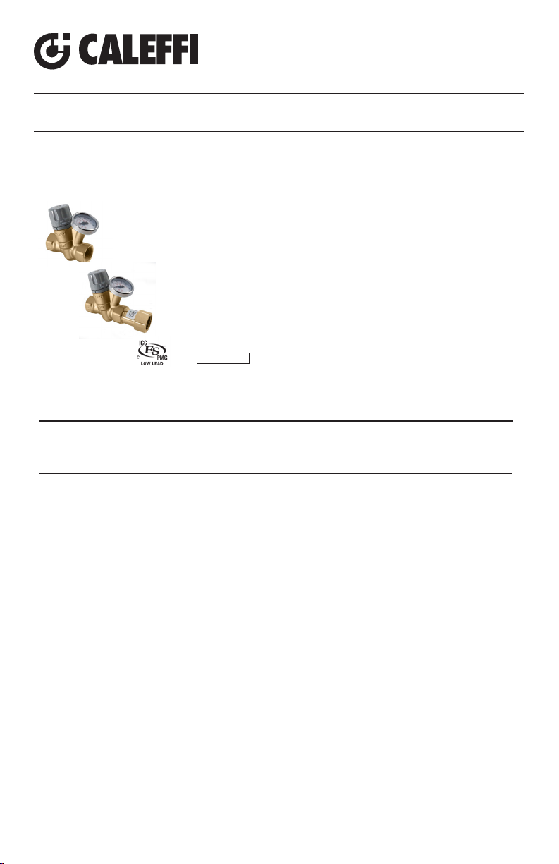
The ThermoSetter™ 1164 series adjustable thermal balancing
valve is used for automatic balancing of recirculation loops in
domestic hot water systems, to speed hot water delivery, reduce
water waste and save energy. The internal thermostatic balancing
cartridge automatically modulates flow to ensure a constant
temperature in the recirculation piping system. The 116 Series
has an adjustment knob with 105°F to 150°F (40°C to 65°C)
temperature scale indication. The adjustment knob is lockable for
tamper-proofing. An integral dry-well holds a slide-in temperature
gauge for local indication, or a sensor for remote temperature
sensing. The optional check valve protects against circuit thermosyphoning.
NSF 61
The valve is ICC-ES certified to NSF/ANSI 61 (180°F/82°C Commercial Hot) and NSF/ANSI 372, low
lead laws. It meets codes IPC, IRC, UPC and NPC for use in accordance with the US and Canadian
plumbing codes.
Product range
1164 series
gauge, w/ and w/o check valve.........................connections ½” and ¾” NPT female
ThermoSetter, models w/ and w/o temperature
1164 Series
Technical specifications
Materials
Body: DZR low-lead brass EN 12165 CW724R
Adjustable cartridge: PSU
Springs: Stainless steel EN 10270-3
(AISI 302)
Hydraulic seals: peroxide-cured EPDM
Adjustment knob: ABS
Performance
Suitable fluid: water
Max. working pressure: 230 psi (16 bar)
Max. differential pressure: 15 psi (1 bar)
Adjustable temperature range:
105–150°F (40 – 65°C)
Factory setting: 135°F (58°C)
Max. inlet temperature: 195°F (90°C)
Cv (Kv) max: 2.1 (1.8)
Cv (Kv) min: 0.35 (0.3)
Cv (Kv) design: 0.69 (0.6)
Certifications
1. Complies with codes IPC, IRC, UPC and
NPC.
2. ICC-ES certified to NSF/ANSI 61
(180°F/82°C Commercial Hot), file
PMG-1512.
3. NSF/ANSI 372, low lead certified by ICCES, file PMG-1360.
Connections
Main connnections:
½” NPT female
¾” NPT female
Temperature gauge/probe pocket:
Ø 10 mm metric
Temperature gauge code 116010
Scale: 30 - 180°F (0–80°C)
Diameter: 1½” (40 mm)
Stem diameter: 0.35” (9 mm)
1
Page 2
SAFETY INSTRUCTION
This safety alert symbol will be used in this manual to draw attention to safety related instructions.
When used, the safety alert symbol means ATTENTION! BECOME ALERT! YOUR SAFETY IS
INVOLVED! FAILURE TO FOLLOW THESE INSTRUCTIONS MAY RESULT IN A SAFETY
HAZARD.
WARNING: This product can expose you to chemicals including lead, which is known
to the State of California to cause cancer and birth defects or other reproductive harm.
For more information go to www.P65Warnings.ca.gov.
CAUTION: All work must be performed by qualified personnel trained in the
proper application, installation, and maintenance of systems in accordance
with all applicable codes and ordinances.
CAUTION: Over-tightening and breakage can occur with the use of Teflon
®
pipe joint compounds. Teflon® provides lubricity so that care must be
exercised not to over-tighten joints. Failure to follow these instructions
could result in property damage and /or personal injury.
WARNING: System fluids are under pressure or temperature can be
hazardous. Be sure the pressure has been reduced to zero and the
system temperature is below 100°F (38°C). Failure to follow these
instructions could result in property damage and/or personal injury.
CAUTION: If the series ThermoSetter balancing valve is not installed,
commissioned and maintained properly, according to the instructions contained
in this manual, it may not operate correctly and may endanger the user.
CAUTION: Make sure that all the connecting pipework is water tight.
Caleffi shall not be liable for damages resulting from stress corrosion, misapplication or misuse of it products.
LEAVE THIS MANUAL FOR THE USER.
2
Page 3
CONSIGNE DE SÉCURITÉ
Ce symbole d'avertissement servira dans ce manuel à attirer l'attention sur la sécurité concernant
instructions. Lorsqu'il est utilisé, ce symbole signifie. ATTENTION! DEVENEZ ALERTE ! VOTRE
SÉCURITÉ EST EN JEU ! NE PAS SUIVRE CES INSTRUCTIONS PEUT PROVOQUER UN
AVERTISSEMENT:
Ce produit peut vous exposer à des produits chimiques comme
le plomb, qui est connu dans l’État de Californie pour causer le cancer, dommages à la
naissance ou autre. Pour plus d’informations rendez-vous www.P65Warnings.ca.gov.
ATTENTION: Tous les travaux doivent être effectués par du personnel
qualifié formé à la bonne application, installation et maintenance des systèmes
conformément aux codes et règlements locaux.
ATTENTION: Un serrage excessif et la rupture peut se produire avec
l’utilisation de composés à joint de tuyau en Téflon®. Pouvoir lubrifiant Teflon®
permet de sorte qu’il faut prendre soin de ne pas trop serrer les articulations.
Le non-respect de ces instructions peut entraîner des dommages matériels
et/ou des blessures.
AVERTISSEMENT: Les liquides du système sont sous pression ou de la
température peuvent être dangereux. Être sûr que la pression a été réduite
à zéro et la température du système est inférieure à 100°F (38°C). Le nonrespect de ces instructions peut entraîner des dommages matériels et/ou des
blessures.Le non-respect de ces instructions peut entraîner des dommages
matériels et/ou des blessures.
ATTENTION: Si le vanne d’équilibrage, Série ThermoSetter, n'est pas installé,
mis en service et entretenu correctement, selon les instructions contenues dans ce
manuel, il peut ne pas fonctionner correctement et peut mettre en danger l'utilisateur.
ATTENTION: S'assurer que tous les raccordements sont étanches.
Caleffi ne pourra être tenue responsable des dommages résultant de la corrosion, d’une mauvaise
utilisation ou une mauvaise utilisation des produits.
LAISSEZ CE MANUEL AVEC L’UTILISATEUR
3
Page 4
Cv
max
T (°F)
G (gpm)
Cv
min
80
120
130
140
180
150
160
170
T
set
(2.1)
(0.35)
Cv
design
(0.69)
1
2
3
2
Thermostatic control,
1
1164xxA series
3
Thermostatic control with check valve,
11614xAC series
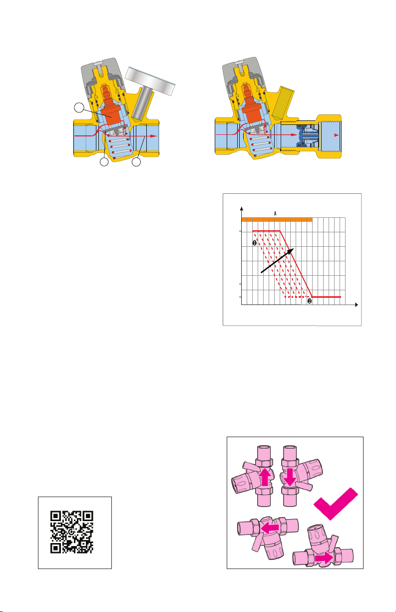
Function A
At the set temperature, the valve plug (1),
controlled by the thermostatic balancing cartridge
(2), gradually closes the outlet to the minimum
flow (3). The outlet never fully closes to always
allow a minimum flow for temperature sensing
and to prevent recirculation pump dead-heading.
If the temperature decreases, the outlet increases,
causing flow and thus temperature to increase
back to the set temperature as shown in curve
1. If temperature exceeds the set-point, the plug
stays in the minimum closed position as shown
in curve 2.
Installation
Before installing the ThermoSetter, flush the pipes to make sure that impurities in system
will not interfere with valve performance. Strainers of sufficient capacity at the inlet from the
water main are highly recommended. The ThermoSetter can be installed in any position,
vertical or horizontal, following the flow direction indicated by the arrow on the valve body.
The ThermoSetter must be installed according to the diagrams given in this manual. It must
be installed to allow free access to for checking on operation and maintenance procedures.
Scan to view
Installation Tip
·
116 ThermoSetter
TM
4
Page 5
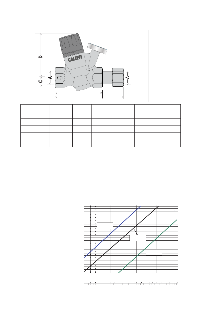
Dimensions
3 4.5 6 7 8.810 1213.2
7.25
10
14.5
10˚F ∆T
inlet to setpoint
B
B’
Code* A B B* C D
116440A(C) ½" NPT F 2
116441A(C)** ½" NPT F 2
116450A(C) ¾" NPT F 2
116451A(C)** ¾" NPT F 2
13
/16" 4 13/16" ¾" 3" 1.6 (1.8) / 0.72 (0.82)
13
/16" 4 13/16" ¾" 3" 1.5 (1.7) / 0.68 (0.77)
13
/16" 5" ¾" 3" 1.6 (1.8) / 0.72 (0.82)
13
/16" 5" ¾" 3" 1.5 (1.7) / 0.68 (0.77)
*Models with check valve tail-piece (C) end-to-end dimension is B'.
**with integral outlet temperature gauge.
Wt
lb (kg) / C-lb (kg)
Flow characteristics
The ThermoSetter thermostatic balancing valve is designed to balance individual branches of
domestic hot water recirculation systems, based on the temperature at the valve. It automatically
modulates flow to maintain hot water availability to all fixtures in the branch circuit. The valve is at
minimum flow (Cv = .35) when the incoming water temperature is equal to the set-point position
of the adjustment dial. The valve opens as incoming water temperature drops.
For pressure loss calculations
in the recirculation system,
follow traditional pipe sizing
and head loss practices.
For pressure loss calculations
across the ThermoSetter
valve, use the design curve
shown in the graph below.
This line represents a typical
valve position under normal
working conditions (∆T=
10°F). Determine the pressure
drop across the valve by
selecting the branch design
GPM on the graph X-axis,
draw a vertical line up to
the “design” curve, then go
across to the Y-axis to find
the design pressure drop.
Include that pressure drop
in your head loss calculations
for the circuit.
∆p (psi)
3.00
2.00
1.50
1.00
0.70
0.50
0.30
0.20
0.15
0.10
0.07
0.05
0.03
0.02
0.01
6
5
4
0.35 Cv
minimum
0.69 Cv
design
2.1 Cv
full open
0.08
0.30
0.10
0.36
0.12
0.48
0.16
0.20
0.90
0.60
0.40
0.30
1.20
0.70
0.50
1.80
0.60
0.90
1.00
2.40
3.00
3.60
4.20
∆p (kPa)
20
13
11
7.0
3.5
2.0
1.4
1.0
0.7
0.5
0.3
0.2
0.1
2. 5
2.00
1.40
1.80
(/m) (gpm)
4.80
Flow rate
5.40
6.00
7.80
5
Page 6
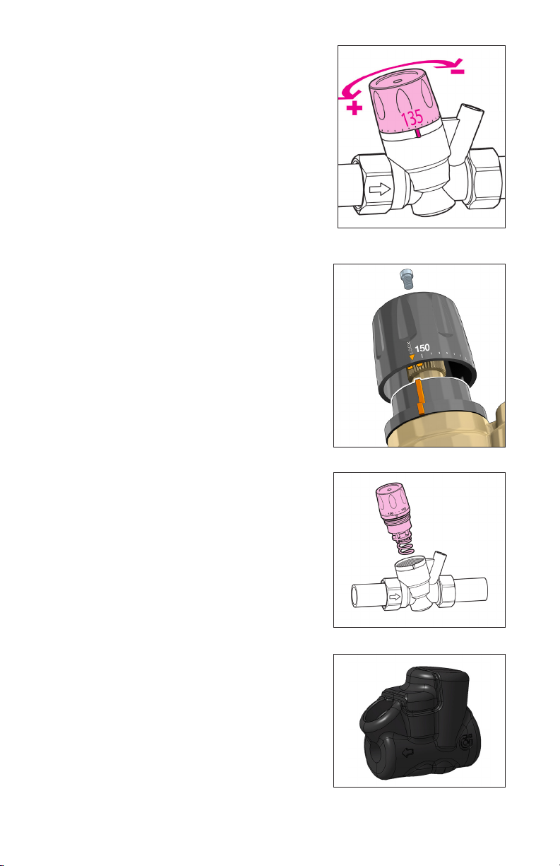
Temperature adjustment
Set the desired recirculation system temperature by turning
the adjustment knob. The graduated scale shows the
temperatures at which the indicator can be set.
Adjustment locking
After adjusting the temperature, the setting can be locked
at the desired value using the adjustment knob. Unscrew
the locking screw at the top of the adjustment knob,
remove the knob and then put it back on so that the internal
groove couples with the protrusion on the knob holder nut.
When this block is used, the reference of the indication of
the temperature values on the knob is lost. To restore it,
completely unscrew the lcoking screw. Reposition the knob
on MAX value. Tighten the locking screw.
Maintenance
The balancing adjustment cartridge can be removed
from the valve body for periodic inspection, cleaning or
Insulation shell
The ThermoSetter 1164 series thermal balancing valve
can be supplied with an optional insulation shell, code
CBN116440 purchased separately, to minimize heat loss.
6
Page 7
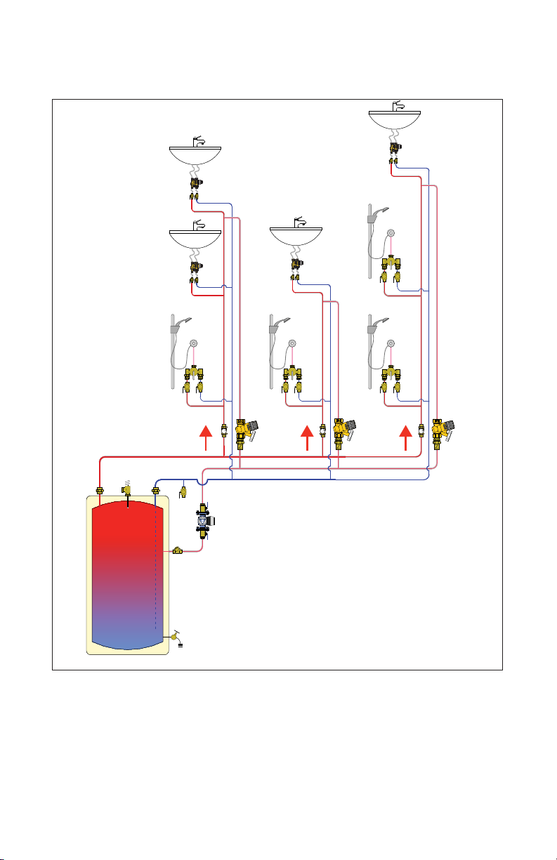
Application diagram
Hot water recirculation with thermal balancing valves
140°F
135°F
135°F
NOTE: Do not set at temperatures >120ºF if
anti-scald valves are not installed at the fixtures.
120°F
7
135°F
Page 8

NOTES
Caleffi North America, Inc.
3883 W. Milwaukee Road
Milwaukee, WI 53208
T: 414.238.2360 F: 414.238.2366
8
3-20-2020
 Loading...