

Page 1
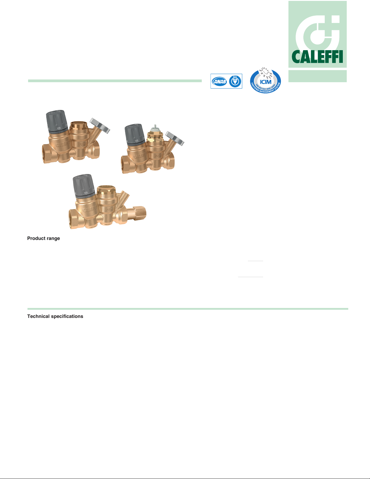
THERMOSETTER
™
Recirculation thermal balancing valve
116 series
ACCREDITED
ISO 9001 FM 21654
Function
The THERMOSETTER™ adjustable thermal balancing valve is used for
automatic balancing of recirculation loops in domestic hot water systems, to
speed hot water delivery, reduce water waste and save energy. The internal
thermostatic balancing cartridge automatically modulates flow to ensure a
constant temperature in the recirculation piping system. The 116 Series has
an adjustment knob with 95°F to 140°F (35°C to 60°C) temperature scale
indication. An integral dry-well holds a slide-in temperature gauge for local
indication, or a sensor for remote temperature sensing. The optional check
valve protects against circuit thermo-syphoning.
The 1162xx Series is available with a “disinfection” by-pass cartridge, for
use in systems which are designed to perform thermal disinfection for
prevention of Legionella. When the disinfection cartridge senses 160°F
(70°C) water, indicating disinfection control mode, it automatically opens a
by-pass flow path to allow sufficient flow for disinfection to occur. When the
temperature drops back to normal range, the disinfection by-pass cartridge
closes to return flow control to the balancing cartridge.
The 1163xx Series is also available with a "disinfection" valve that is
controlled by a 24V spring return thermo-electric actuator, rather than
thermostatically, thus allowing thermal disinfection mode to be controlled
remotely by an automation system.
01325/17 NA
Product range
1161_0A series
1161_0AC series Thermal balancing valve with check valve ................................................................................................................................size ½” & ¾” NPT female
1161_1A series
1161_1AC series Thermal balancing valve with temperature gauge and check valve ..........................................................................................size ½” & ¾” NPT female
1162__A series
1162__AC series Thermal balancing valve with thermostatic bypass cartridge, temperature gauge and check valve ..........................................size ½” & ¾” NPT female
1163__A series
1163__AC series Thermal balancing valve with actuator bypass valve, temperature gauge and check valve ......................................................size ½” & ¾” NPT female
Technical specifications
Materials:
Body: DZR low-lead brass
Adjustable cartridge: stainless steel & copper
Springs: stainless steel AISI 302 (EN 10270-3)
Hydraulic seals: EPDM
Adjustment knob: ABS
Performance:
Suitable fluid: water
Max. working pressure: 230 psi (16 bar)
Max. differential pressure: 15 psi (1 bar)
Max. inlet temperature: 195°F (90°C)
Adjustment temperature range: 95-140°F (35–60°C)
Flow Cv (Kv) max: 2.1 (1.8)
Flow Cv (Kv) min: 0.23 (0.2)
Flow Cv (Kv) design: 0.52 (0.45)
Disinfection performance:
Disinfection temperature: 160°F (70°C)
Closing temperature: 170°F (75°C)
Flow Cv (Kv) disinfection: 1.2 (1.0)
Thermal balancing valve ...........................................................................................................................................................size ½” & ¾” NPT female
Thermal balancing valve with temperature gauge .....................................................................................................................size ½” & ¾” NPT female
Thermal balancing valve with thermostatic bypass cartridge and temperature gauge ..............................................................size ½” & ¾” NPT female
Thermal balancing valve with actuator bypass valve and temperature gauge ...........................................................................size ½” & ¾” NPT female
Connections:
Main connections:
Temperature gauge/sensor dry-well: Ø 10 mm metric
Temperature gauge code 116010
Scale: 30 - 180°F (0–80°C)
Diameter: 1½" (40 mm)
Stem diameter: 0.35" (9 mm)
Technical specifications of insulation
Materials: closed cell expanded PE-X
Thickness: ½ inch (13 mm)
Density: -internal part: 1.9 lb/ft³ (30 kg/m³)
-external part: 5.0 lb/ ft³ (80 kg/m³)
Thermal conductivity (DIN52612):
- at 32°F (0°C): 0.82 BTU · in/hr · ft² · °F (0.0345 W/(m · K))
- at 105°F (40°C): 0.94 BTU · in/hr · ft² · °F (0.0398 W/(m · K))
Coefficient of resistance to the diffusion of vapor: > 1,300
Working temperature range: 32–212°F (0–100°C)
Flammability (ASTM D 635): Class VO
Certications: NSF/ANSI 372-2011, low lead certified by
ICC-ES, file PMG-1360.
½" NPT female
¾" NPT female
Page 2
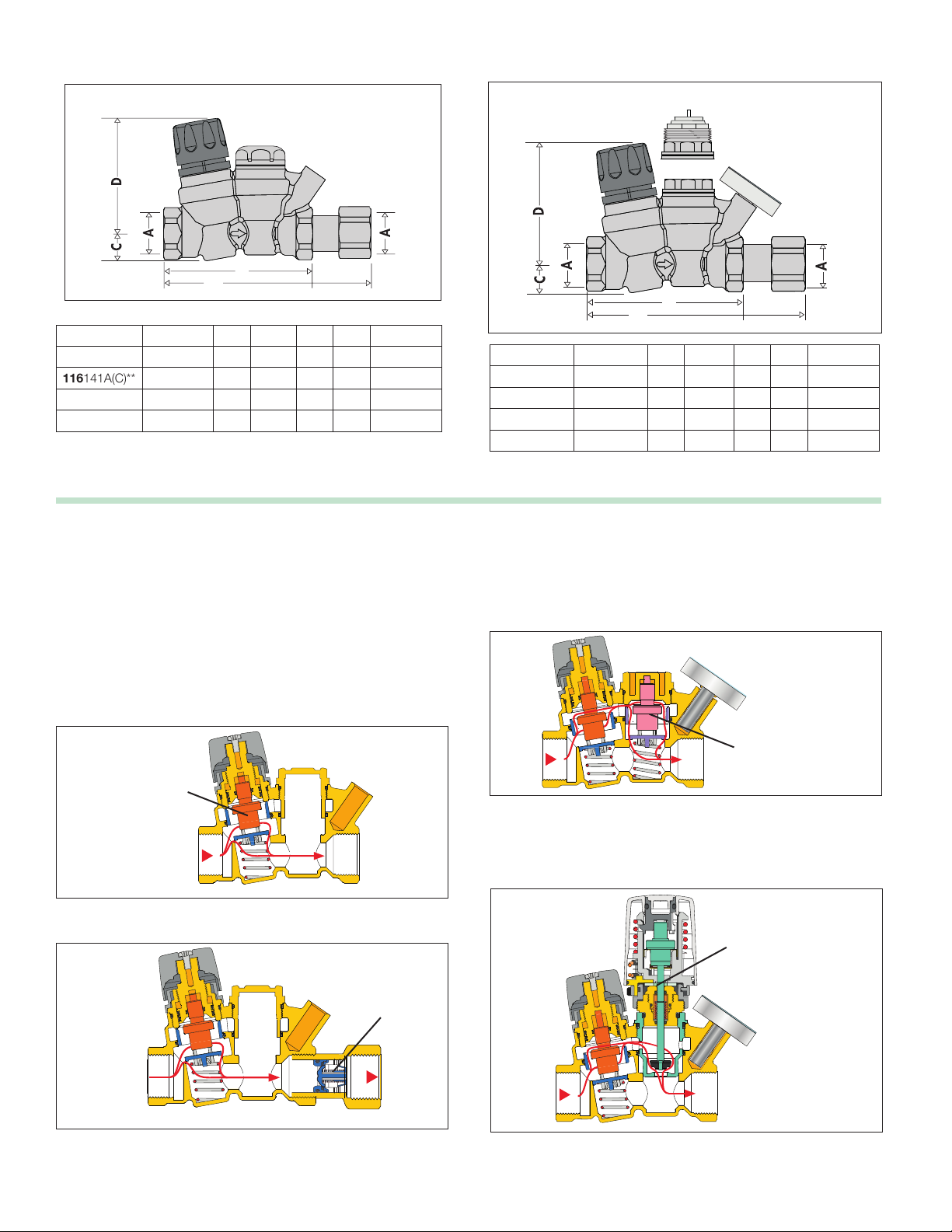
Dimensions
A
B C
DMass (kg)
DN
1/2" 100
3/4 100
18,5
18,5
74,5
74,5
0,750
0,700
15
20
B
B’
B
B’
Code A B B'* C D Wt (lb/kg)
116140A(C) ½" NPT F 4" 5
116141A(C)** ½" NPT F 4" 5
116150A(C) ¾" NPT F 4" 5
116151A(C)** ¾" NPT F 4" 5
7
/16" ¾" 3" 1.7 / 0.75
7
/16" ¾" 3" 1.7 / 0.75
5
/8" ¾" 3" 1.5 / 0.70
5
/8" ¾" 3" 1.5 / 0.70
*Models with check valve tail-piece (C) end-to-end dimension is B'.
**with integral outlet temperature gauge.
1163xx
1162xx
B
B’
Code A B B'* C D Wt (lb/kg)
116240A(C) ½" NPT F 4" 5
116250A(C) ¾" NPT F 4" 5
116340A(C) ½" NPT F 4" 5
116350A(C) ¾" NPT F 4" 5
7
/16" ¾" 3" 1.7 / 0.75
5
/8" ¾" 3" 1.5 / 0.70
7
/16" ¾" 3" 1.7 / 0.75
5
/8" ¾" 3" 1.5 / 0.70
Operating principle
The THERMOSETTER™ adjustable thermal balancing valve, 116 series
models, installed at the end of each branch of the domestic hot water
recirculation system, automatically maintains the set temperature. It
controls the water flow rate according to the inlet temperature with the
internal adjustable thermostatic cartridge. The thermostatic cartridge
modulates the valve opening in response to changing water temperature,
and when reaching the temperature setting, closes the valve to minimum
flow position. A recirculation pump distributes flow to all the branches
resulting in effective automatic thermal balancing. The automatic response
allows each hot water branch to deliver hot water to each fixture. The
THERMOSETTER™ works perfectly with variable speed recirculation
pumps for optimal energy usage.
Adjustable
balancing
cartridge
Optional check valve are available for all models, which protect against
circuit thermo-syphoning.
Optional
check
valve
For systems using thermal disinfection for Legionella growth protection,
the 1162xx series models incorporate a second thermostatic by-pass
cartridge that activates at 160°F. A second flow path opens providing
flow for the disinfection process which is independent of the primary
balancing cartridge.
Thermal
disinfection
by-pass
cartridge
Alternately, the 1163xx series models incorporate a by-pass valve for
thermal disinfection which is activated by a optional field mounted
thermo-electric actuator, code 656 series, controlled by a automation
system.
Thermal
disinfection
by-pass
valve
Page 3
Cv
max
T (°F)
G (gpm)
Cv
dis
Cv
min
Automatic disinfection
C
Thermal disinfectionTemperature control
100
140
150
160
190
170
180
185
T
set
(2.1)
(1.2)
(0.23)
Cv
design
(0.52)
Operating mode
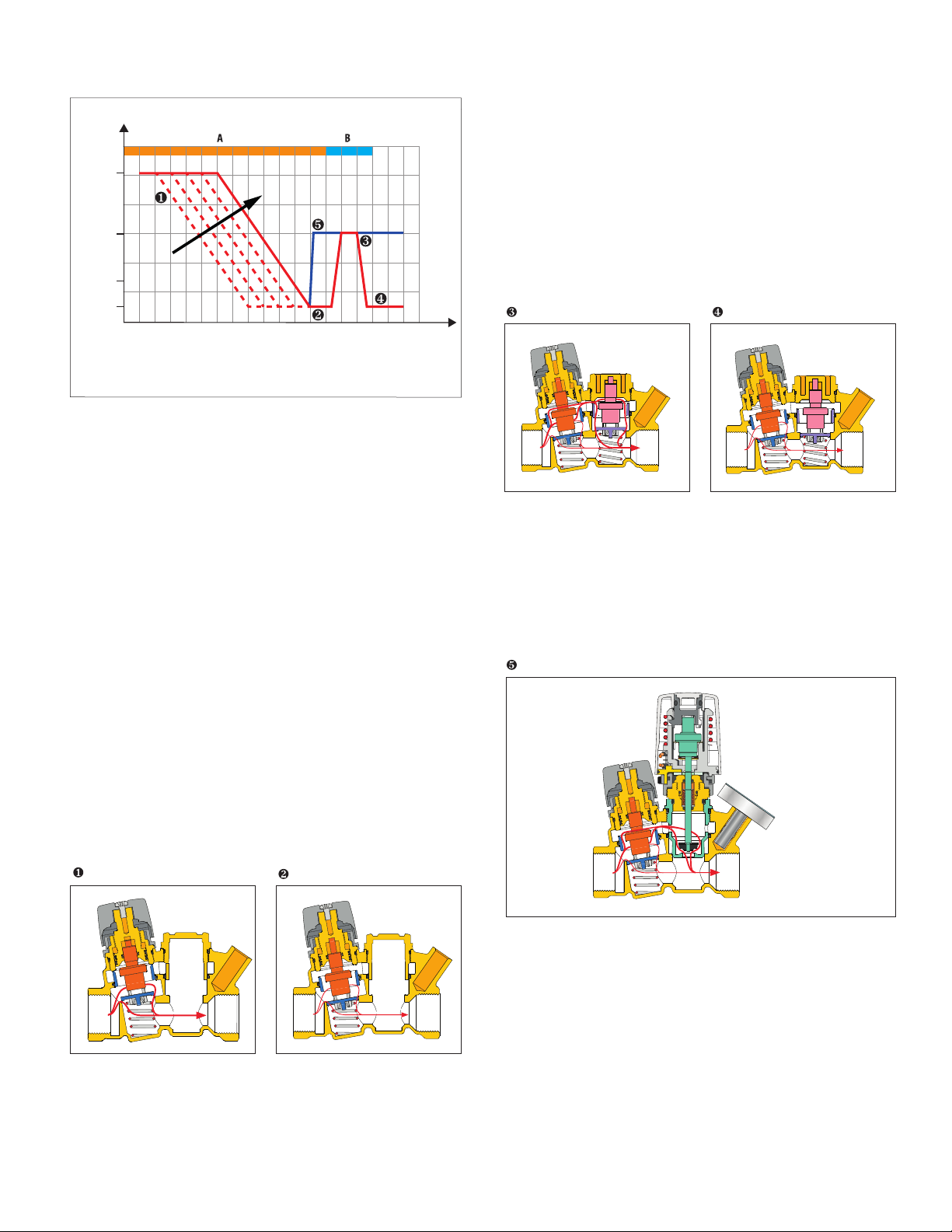
The graph shows the variation of the Cv value depending on the valve
operating mode (A, B, C) and on the inlet temperature of the domestic
hot water.
Operating mode A - Temperature control
Cv max: = 2.1 maximum flow state when operating in temperature
control mode (cartridge fully open).
Cv min: = 0.23 minimum flow state when operating at set point in
temperature control mode (cartridge nearly closed).
Operating mode B - Automatic thermostatic disinfection
Cv dis: = 1.2 maximum flow state when operating in thermostatic
controlled thermal disinfection mode with a temperature of 160°F (70°C).
Operating mode C - Actuator-controlled disinfection
Cv dis: = 1.2 maximum flow state when operating in actuator-controlled
thermal disinfection mode using a thermo-electric actuator, code 656
series.
Operating mode B - Automatic thermostatic disinfection
The 1162xx series operating characteristic curves for operating mode B
are curves 1, 2, 3 and 4. When a temperature higher than about 155°F
(68°C) is reached, a by-pass passage begins to open to activate the
second thermostatic cartridge which controls the thermal disinfection
process, allowing flow independent of the operation of the thermostatic
balancing cartridge. This allows water flow through a special by-pass
port, opening the flow path up until the temperature of 160°F (70°C) is
attained shown in curve 3. If the temperature continues rising beyond
this point, the flow is reduced through the by-pass port to allow thermal
balancing even during the disinfection process. When temperature
reaches about 170°F (75°C), the closes the disinfection by-pass port to
protect the system fixtures from the effects of excessive temperatures,
as shown in curve 4.
Thermostatic disinfection by-pass
Thermal shut-off
Operating mode C - Actuator-controlled disinfection
The 1163xx series operating characteristic curves for operating mode
C are curves 1, 2 and 5. When the disinfection operating temperature
setting of the electronic disinfection system is reached, the thermoelectric actuator 656 series (which is controlled by a dedicated electronic
control system), is energized to operate the by-pass valve to control
the disinfection process, allowing flow independent of the operation of
the thermostatic balancing cartridge shown in curve 5. In this case, the
minimum head loss is produced during this thermal disinfection process.
Electric controlled disinfection by-pass
Operating mode A - Temperature control
At the set temperature, the valve plug, controlled by the thermostatic
balancing cartridge, gradually closes the outlet to the minimum. The outlet
never fully closes to always allow a minimum flow for temperature sensing
and to prevent recirculation pump dead-heading. If the temperature
decreases, the outlet increases, causing flow and thus temperature to
increase back to the set temperature as shown in curve 1. If temperature
exceeds the set-point, the plug stays in the minimum closed position as
shown in curve 2.
Thermostatic balancing control
Minimum flow rate
Page 4
Flow characteristics
4.5 6 7 8.810 1213.2
6
7.25
10
14.5
10˚F ∆T
inlet to setpoint
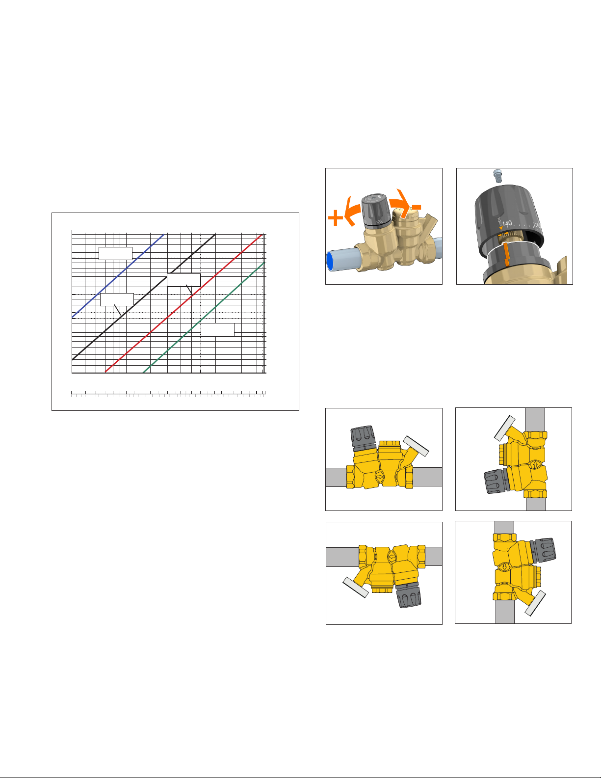
The THERMOSETTER™ thermostatic balancing valve is designed
to balance individual branches of domestic hot water recirculation
systems, based on the temperature at the valve. It automatically
modulates flow to maintain hot water availability to all fixtures in the
branch circuit. The valve is at minimum flow (Cv = .23) when the
incoming water temperature is equal to the set-point position of the
adjustment dial. The valve opens as incoming water temperature drops.
For pressure loss calculations in the recirculation system, follow
traditional pipe sizing and head loss practices. For pressure loss
calculations across the THERMOSETTER™ valve, use the design
curve shown in the graph below. This line represents a typical valve
position under normal working conditions (∆T= 10°F). Determine the
pressure drop across the valve by selecting the branch design GPM
on the graph X-axis, draw a vertical line up to the “design” curve,
then go across to the Y-axis to find the design pressure drop. Include
that pressure drop in your head loss calculations for the circuit.
5
∆p (psi)
4
3.00
2.00
1.50
1.00
0.70
0.50
0.30
0.20
0.15
0.10
0.07
0.05
0.03
0.02
0.01
0.08
0.30
0.10
0.36
minimum
design
0.12
0.48
0.23 Cv
0.52 Cv
0.16
0.60
0.20
0.90
1.2 Cv
by-pass
2.1 Cv
full open
0.40
0.30
1.20
1.80
0.50
0.60
2.40
0.70
3.00
0.90
3.60
1.00
4.20
4.80
1.40
5.40
6.00
1.80
∆p (kPa)
20
13
11
7.0
3.5
2.0
1.4
1.0
0.7
0.5
0.3
0.2
0.1
2. 5 3
2.00
Flow rate
7.80
(/m) (gpm)
Temperature adjustment and locking
Set the desired recirculation system temperature by turning the
adjustment knob. The graduated scale shows the temperatures at which
the adjustment knob can be set.
After adjusting the temperature, the setting can be locked at the desired
value using the adjustment knob. Unscrew the locking screw at the top
of the adjustment knob, remove the knob and then put it back on so that
the internal groove couples with the protrusion on the knob holder nut.
When this lock is used, the reference of the indication of the temperature
values on the knob is lost. To restore it, completely unscrew the locking
screw. Reposition the knob on MAX value. Insert and tighten the locking
screw.
Installation
Before installing the THERMOSETTER™, flush the pipes to make sure
that impurities in the system will not interfere with valve performance.
Strainers of sufficient capacity at the inlet from the water main are highly
recommended. The THERMOSETTER™ can be installed in any position,
vertical or horizontal, following the flow direction indicated by the arrow
on the valve body. The THERMOSETTER™ must be installed according
to the diagrams given in this manual. It must be installed to allow free
access for checking on operation and maintenance procedures.
The “by-pass mode” curve in the chart above shows the head loss of
the valve when it is in by-pass thermal disinfection mode for Legionella
control.
System sizing
For flow rate calculations in the recirculation system, the pump is sized
to provide sufficient flow to compensate for the total heat loss in all the
supply branches to the furthest fixture in each circuit. Heat loss in return
lines, downstream of the balancing valves, is irrelevant and not included
in the flow rate calculations.
The flow rate calculation formula to use is: GPM = BTUh/∆T x 500.
Common design practice for recirculation lines is to use a ∆T of 10°F.
This is the temperature difference of the recirculating water between
the heat source and to the furthest fixture in each circuit. Assuming the
common value of a ∆T = 10°F, the equation simplifies to:
GPM = BTUh/5000.
BTUh heat loss, will vary based on pipe type and insulation. Heat loss
tables and charts are available from a variety of sources.
Example:
Calculate the recirculation circuit flow rate for 100 feet of ¾” non-insulated
copper pipe. Assume an average heat loss of 30 BTU/h per foot.
30 BTUh per foot x 100 feet = 3000 BTU/h heat loss in the supply piping.
Flow rate = 3000 / 5000 = 0.6 GPM flow required in that circuit.
Page 5
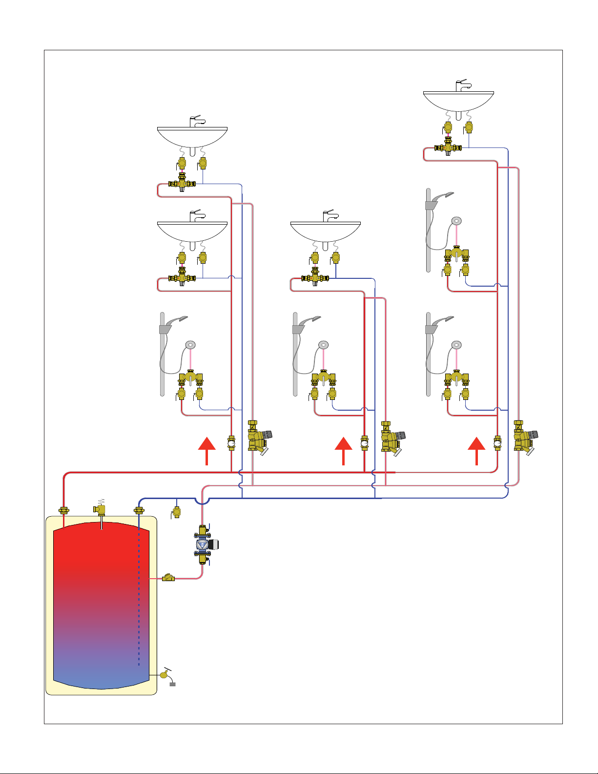
Typical application diagram
130°F
130°F
130°F
140°F
120°F
NOTE: Do not set at temperatures >120ºF if anti-scald valves are not installed at the fixtures.
Hot water recirculation with thermal balancing valves
Page 6
Maintenance
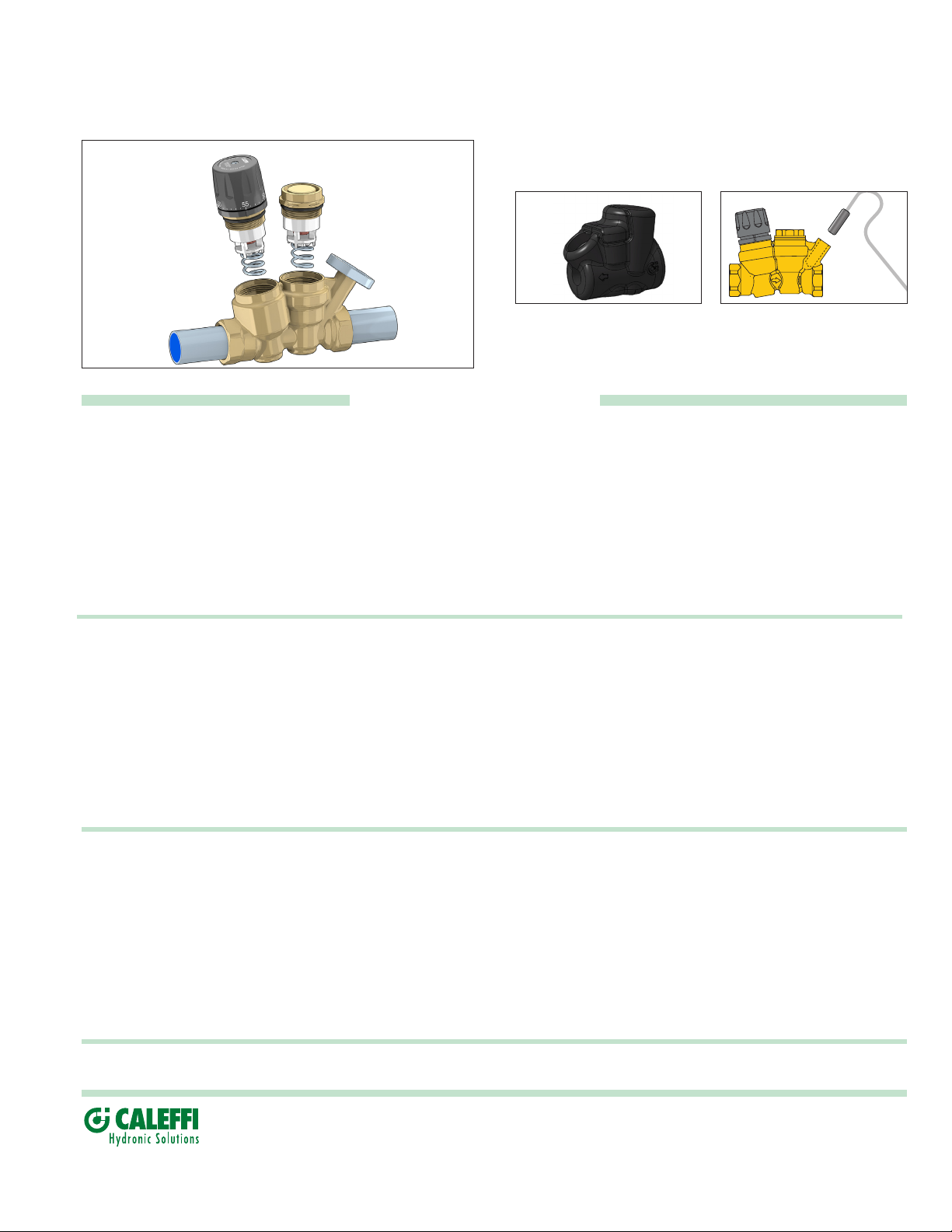
Both the adjustable balancing cartridge and the disinfection control
cartridge can be removed from the valve body for periodic inspection,
cleaning or replacement.
Accessories
THERMOSETTER™ codes 116140A and 116150A come standard
without temperature gauge, but temperature gauge, code 116010 can
be field-installed later for confirming the temperature of the hot water in
the circuit.
The temperature gauge dry-well can also be used for inserting a special
immersion probe (with Ø < 10 mm) for remote control of the disinfection
temperature by a dedicated electronic control unit.
Insulation shell
The THERMOSETTER™ thermal balancing valve can be supplied with
an optional insulation shell, code CBN116140 purchased separately, to
minimize heat loss.
SPECIFICATION SUMMARY
Series 1161
Thermal balancing valve for domestic hot water recirculation circuits. Dezincification resistant low-lead brass body (<0.25% Lead
content) certified to ANSI/NSF 372-2011 by ICC-ES. Sizes ½" and ¾" with NPT female connections. Adjustable thermostatic
cartridge. EPDM hydraulic seals. Temperature gauge/probe dry-well Ø 10 mm. Maximum working pressure 230 psi (16 bar).
Maximum differential pressure 15 psi (1 bar). Adjustment temperature range 95°F to 140°F (35°C-60°C). Flow rating: 2.1 Cv
(1.8 Kv) maximum, 0.23 Cv (0.2 Kv) minimum, 0.52 Cv (0.45 Kv) design. Equipped with: ABS adjustment knob with temperature
adjustment scale for manual setting and tamper-proof adjustment locking screw. Provide with optional outlet temperature gauge
with 30°F to 180°F (0°C-80°C) temperature scale. Provide with optional check valve. Pre-formed insulation shell is available for
field installation.
Series 1162
Thermal balancing valve for domestic hot water recirculation circuits with thermostatic by-pass valve for thermal disinfection
function. Dezincification resistant low-lead brass body (<0.25% Lead content) certified to ANSI/NSF 372-2011 by ICC-ES.
Sizes ½" and ¾" with NPT female connections. Adjustable thermostatic cartridge. EPDM hydraulic seals. Temperature gauge/
probe dry-well Ø 10 mm. Maximum working pressure 230 psi (16 bar). Maximum differential pressure 15 psi (1 bar). Adjustment
temperature range 95°F to 140°F (35°C-60°C). Disinfection temperature 160°F (70°C). Closing temperature 170°F (75°C). Flow
rating: 2.1 Cv (1.8 Kv) maximum, 1.2 Cv (1.0 Kv) disinfection, 0.23 Cv (0.2 Kv) minimum, 0.52 Cv (0.45 Kv) design. Equipped with:
ABS adjustment knob with temperature adjustment scale for manual setting and tamper-proof adjustment locking screw, outlet
temperature gauge with 30°F to 180°F (0°C-80°C) temperature scale. Provide with optional check valve. Pre-formed insulation
shell is available for field installation.
Series 1163
Thermal balancing valve for domestic hot water recirculation circuits with by-pass valve for thermal disinfection function with
optional code 656 series thermo-electric actuator. Dezincification resistant low-lead brass body (<0.25% Lead content) certified
to ANSI/NSF 372-2011 by ICC-ES. Sizes ½" and ¾" with NPT female connections. Adjustable thermostatic cartridge. EPDM
hydraulic seals. Temperature gauge/probe dry-well Ø 10 mm. Maximum working pressure 230 psi (16 bar). Maximum differential
pressure 15 psi (1 bar). Adjustment temperature range 95°F to 140°F (35°C-60°C). Disinfection temperature 160°F (70°C). Closing
temperature 170°F (75°C). Flow rating: 2.1 Cv (1.8 Kv) maximum, 1.2 Cv (1.0 Kv) disinfection, 0.23 Cv (0.2 Kv) minimum, 0.52 Cv
(0.45 Kv) design. Equipped with: ABS adjustment knob with temperature adjustment scale for manual setting and tamper-proof
adjustment locking screw, outlet temperature gauge with 30°F to 180°F (0°C-80°C) temperature scale. Provide with optional check
valve. Pre-formed insulation shell is available for field installation.
We reserve the right to make changes and improvements to the products and related data in this publication, at any time and without prior notice.
Caleffi North America, Inc.
3883 W. Milwaukee Road
Milwaukee, WI 53208
Tel: 414-238-2360 · Fax: 414-238-2366
[email protected] · www.caleffi.com
© Copyright 2017 Caleffi North America, Inc.
 Loading...