

Page 1

MIN 3xd
h
MIN 5xd
h
UG-3
UG-3
FLÄKT
FAN
MIN 5xd
h
UG-3
MIN 3xd
h
UG-3
KANALBÖJ
DUCT BEND
UG-3
MIN 5xd
h
UG-3
MIN 3xd
h
UG-3
MIN 3xd
h
AVGRENING
DUCT BRANCHING
UG-3
UG-3
MIN 3xd
h
MIN 5xd
h
LUFTBEHANDLINGSAGGREGAT
AIR HANDLING UNIT
FRÅNLUFT / RETURN AIR
TILLUFT / INLET AIR
d = D
Ø D
h
d =
h
2xHxW
H+W
H
W
5 d
h
3 d
h
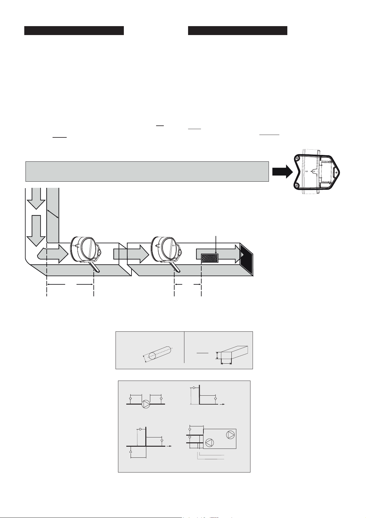
Exempel på installation
efter böjd trumdel.
Example of location after
change of duct direction.
Observera fotens form av en pil, vilken skall peka i luftströmmens riktning.
Note the foot’s shape of an arrow, which shall be installed in the air flow direction.
Returluftintag.
Air inlet.
Exempel på installation
före returluftintag.
Example of location before
air inlet.
Vid stora temperaturskillnader t.ex. utomhus eller på kallvindar
måste Uniguard isoleras från omgivande luft. Se punkt 9.
Where large temperature variations occur, e.g. on outdoor
locations or in areas subject to external temperatures (roof,
attics), the Uniguard should be insulated, see para 9.
d
h
UG-3-A4O & UG-3-A5O INSTALLATION INSTRUCTION
SV EN DE ES
DE
SVENSKA
Montering och placering.
Uniguard skall placeras i flödesriktningen, enligt riktningspilen
(se Uniguardfotens form eller ovansidan huset). Uniguard är
lägesoberoende och kan monteras på valfri sida av kanalen men
vid rektangulär kanal bör detektorn monteras på den kortaste
sidan, för att samla in luft från så stor del av kanalen som möjligt.
Vi rekommenderar att Uniguard monteras på minst samma avstånd
från kyl- och värmebatterier eller luftfuktare som luftflödesgivare.
Den bör dessutom placeras så, att avståndet före närmaste
störning i kanalen (t.ex. böj, filter eller spjäll) - i luftflödesriktningen
räknat - är minst lika stort som 3 x kanalens diameter. Närmaste
placering efter sådan störning bör vara 5 x kanaldiametern.
ENGLISH
Mounting and positioning.
The Uniguard should be installed with the air flow direction
arrows (see the Uniguard foot’s shape or on the housing top)
corresponding to the direction of the air flow in the duct. The
Uniguard can be installed on any side of the duct. N.B. Rectangular
ducts: In order to gain maximum air sampling coverage, install the
Uniguard on the shortest side of a rectangular duct.
We recommend that the Uniguard is mounted at an equal distance
from heating, cooling, or humidity devices, and similar to the siting
for flow monitors.
A distance of 3 times the duct diameter should be left before a
damper, filter or change of the duct direction, and 5 times the
diameter after these devices.
CIRKULÄR KANAL
Hydraulisk diameter
CIRCULAR DUCT
Exempel på installation
med störkällor:
- fläkt
- spjäll
- ljuddämpare
© 2018.11.14 R1.7 Calectro AB HFE314
Phone: +46 31-69 53 00 Fax: +46 31-29 32 91 [email protected] www.calectro.se
- batteri
- luftbehandlingsaggregat
- kanalböj
- avgrening
- dimensionsförändring
REKTANGULÄR K ANAL
RECTANGUL AR DUCT
Hydraulic diameter
Example of installation at
sources of interference:
- fan
- damper
- silencer
- battery
- air handling unit
- duct bend
- duct branching
- duct narrowing or expansion
Page 2

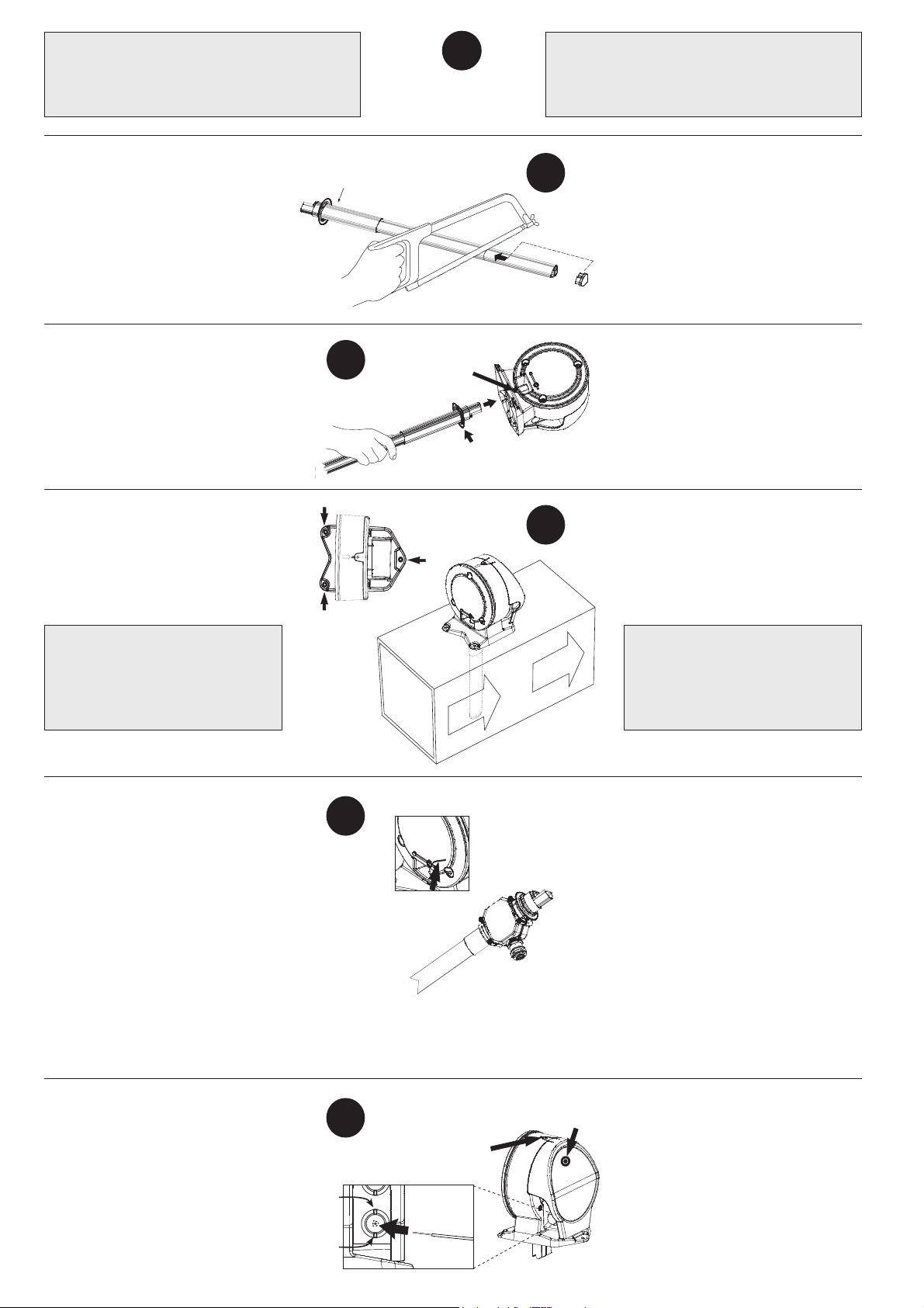
Borra hål i kanalen:
• Håltagning utan monteringsbeslag, ø 38 mm.
• Håltagning med monteringsbeslag och/eller venturirör
med monterad fläkt, ø 51 mm (se punkt 10).
Kapa EJ denna ände!
• Mät ventilationskanalens diameter.
• Kapa eventuellt röret.
• Röret bör täcka minst 90% av
kanalens diameter.
OBS! Se även punkt 8.
• Sätt i ändpluggen.
• Träd på tätningen på röret.
• För in röret i botten på Uniguard.
• Lås fast röret med stoppskruven.
Do NOT cut this end!
3
Stoppskruv.
Locking screw.
1
Tätning.
Gasket.
Drill a hole in the duct:
• Without mounting bracket, ø 38 mm.
• With mounting bracket and/or venturi pipe with
booster fan, ø 51 mm (see para 10).
2
Ändplugg.
End plugg.
• Measure the diameter of the duct.
• Shorten the pipe, if necessary.
• The pipe should penetrate at least 90%
of the width of the duct.
NOTE! See para 8.
• Insert the end plug.
• Mount the black gasket on the pipe.
• Insert the pipe into the bottom of the
Uniguard.
• Secure the pipe with the locking screw.
• Montera röret och detektorn på kanalen.
• Fäst Uniguard på 3 punkter vid pilarnas
markering.
OBS VIKTIGT!
Riktningspilarna (se Uniguardfotens
form eller ovansidan huset) skall ha
samma riktning som luftflödet i kanalen.
Flödesindikator och fläktrör*.
Uniguard är försedd med en indikator, en
plasttunga, som – när detektorn är rätt
installerad – svängs ut av luftströmmen.
OBS!
Rör sig inte indikatorn alls bör man
överväga en omplacering av detektorn,
alternativt montera ett s.k. fläktrör*.
Vid montering av fläktrör används alltid ett
monteringsbeslag.
* Fläktrör är ett standard venturirör med hjälpfläkt,
vilken kräver separat 24V AC/DC matning.
5
Flödesindikator.
Flow indicator.
Venturirör med hjälpfläkt.
Venturi pipe with booster fan.
4
• Mount the pipe and the detector on the duct.
• Secure the bottom of the Uniguard with
the 3 screws, positions marked.
NOTE - IMPORTANT!
The air flow direction arrows (see
the Uniguard foot’s shape or on the
housing top) must have the same
direction as the air flow in the duct.
Flow indicator and booster fan pipe*.
The Uniguard is supplied with an indicator,
a plastic "tongue", which – when the
detector is correctly installed – is bent
outwards due to the airflow.
NOTE!
If the indicator does not move, you should
consider a new mounting positioning of the
Uniguard or install a booster fan venturi pipe.
With installation of a booster fan venturi pipe
a mounting bracket is always used.
* A booster fan pipe is a standard venturi pipe including a
booster fan, which needs separate 24V AC/DC supply.
Elinstallation.
• Öppna locket över kopplingshuset genom
att lyfta på snäpplåset.
• För in kabeln genom valfri Klikseal
kabelgenomföring.
Används annan typ av genomföring
demonteras de förmonterade genom
att först trycka igenom ena sidan och
därefter den andra (1-2).
2
(1)
(2)
6
Snäpplås.
Snap locking.
Resetknapp.
Reset button.
Electrical installation.
• Remove the cover over the printed circuit
board by opening the snap locking.
• Enter the cable through one of the
Klikseal glands.
When using another type of cable gland
dismount the ones already installed by
first pressing one side through the hole
and then the other one (1-2).
Page 3

• Uniguard Superflow har 4 st. (3 st. i
230V varianten) förmonterade IP67
godkända och automatiskt dragavlastande
genomföringar för kabeldiameter
4-11 mm, typ Klikseal.
OBS! Kabeln får endast föras i en
riktning genom Klikseal: in i Uniguard.
Vid ett eventuellt byte av monterad kabel
ska denna klippas av på utsidan av
Uniguard och resten av kabeln dras ur
Klikseal, från insidan.
Klikseal är godkänd enligt EN 50262.
• Anslut elkablarna enligt kopplingsschemat.
UG-3-A4O: 24V AC/DC
UG-3-A5O: 230V AC.
• UG-3-A5O modellen ska strömförsörjas via
en närmonterad nätfrånskiljare som märks:
”Nätfrånskiljare för rökdetektor UG-3-A5O”.
Service
alarm
output
Alarm
output
Alarm
output
Power supply
NC
NC
NO
NC
NO
10
C
9
8
C
7
• Uniguard Superflow has 4 pieces (3 pieces
in 230V variant) pre-mounted IP67
approved glands for cable diameter 4-11
mm, type Klikseal.
NOTE! The cable must only be pulled
through the Klikseal in one direction:
into the Uniguard.
To exchange a mounted cable: cut the
6
cable outside of Uniguard and pull out the
rest from the inside.
5
C
4
3
Klikseal is approved according to EN50262.
• Connect the cables according to the wiring
diagram.
UG-3-A4O: 24V AC/DC
UG-3-A5O: 230V AC.
2
1
• The UG-3-A5O model shall be power
supplied thru a disconnect device, next to
the smoke detector, marked: ”Disconnect
device for smoke detector UG-3-A5O”.
Funktionskontroll.
7
Kontrollera detektorn med rökdetektorprovare
RDP-300.
• För "testhålspluggen" åt sidan och spraya
därefter kortvarigt.
Vid utlöst larm lyser dioden röd på
kretskortet och detektorn samt vid
servicelarm lyser den gul på kretskortet och
grön på detektorn.
• Återställ genom att trycka på den svarta
resetknappen i locket över kopplingshuset.
• VIKTIGT!
Återmontera "testhålspluggen".
Borra EJ hål i plastlocket för skyltar eller
dylikt. Detta kan ge läckage som allvarligt
nedsätter detektorns funktion.
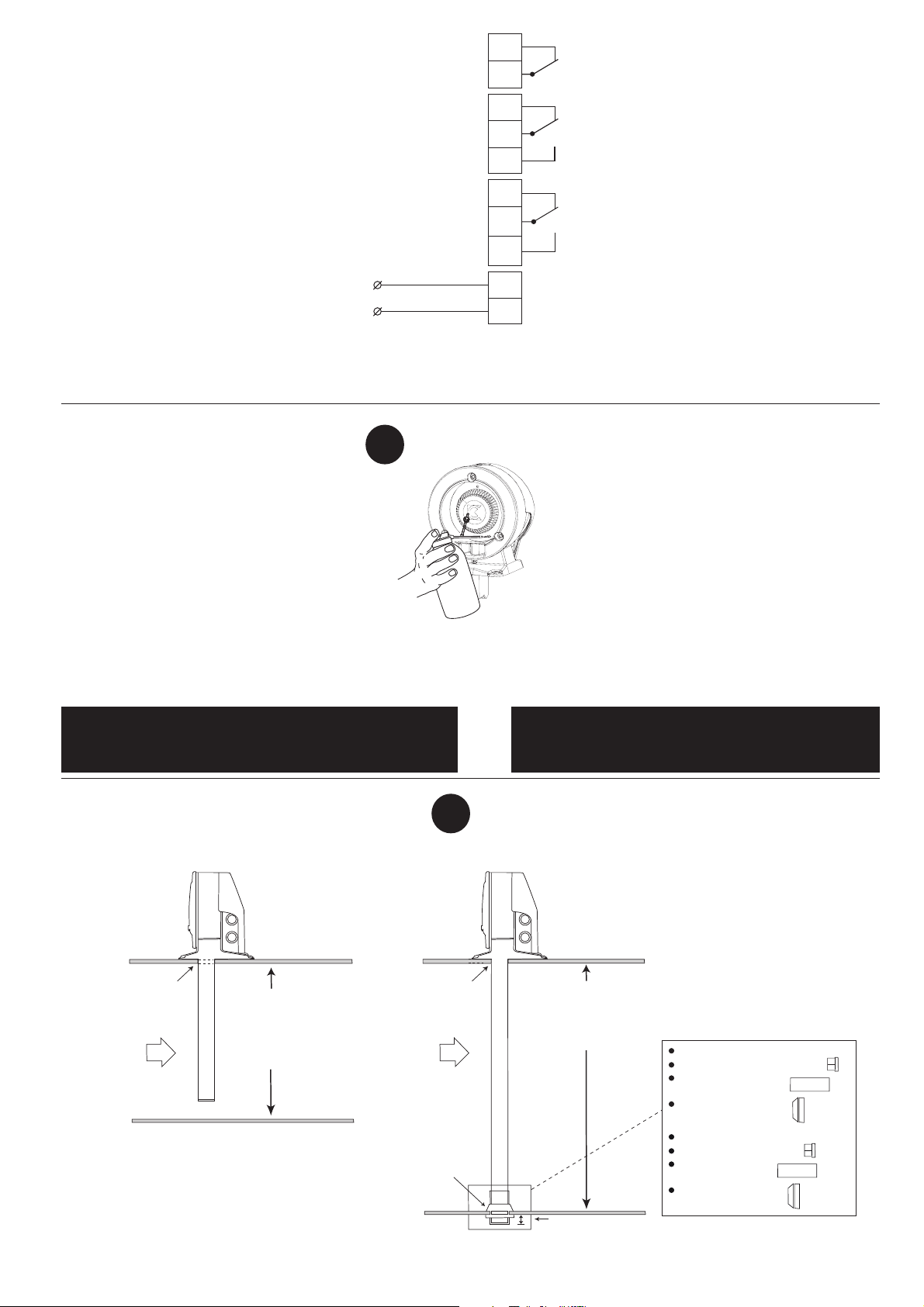
Montering av olika rör i olika kanalbredder.
8
Test of detector.
Check the detector with smoke detector tester
RDP-300.
• Open the "test hole plug" and briefly release
a spray of aerosol.
When alarming the LED lits red on the
printed circuit board and the detector, and
when service alarming it lits yellow on
the printed circuit board and green on the
smoke detector.
• Reset by pressing the black reset button in
the cover over the printed circuit board.
• IMPORTANT!
Reassemble the "test hole plug".
Do not drill any holes in the cover for signs etc.
Holes will cause air leakages and seriously disturbe the
function of the detector.
Fitting of pipes in ducts with different diameter.
Håltagning Ø 38 mm
Drill a hole Ø 38 mm.
För kanaler mindre än 0,6 m används venturirör 0,6 m, standard.
För kanaler mellan 0,6 m och 1,4 m används venturirör 1,5 m.
För kanaler större än 1,4 m används venturirör 2,8 m.
For ducts with a ø of less than 0,6 m use the 0,6 m pipe, standard.
For ducts with a ø of between 0,6 m and 1,4 m use the 1,5 m pipe.
For ducts which are larger than 1,4 m use the 2,8 m pipe.
Max kanalbredd 0,6 m.
Använd venturirör 0,6 m.
Kapa eventuellt till rätt längd.
Max diameter of the duct 0,6 m.
Use the venturi pipe 0,6 m.
Shorten the pipe, if necessary.
Håltagning Ø 38 mm
Drill a hole Ø 38 mm.
OBS!
Håltagning
Ø 51 mm.
NOTE!
Drill a hole
Ø 51 mm.
Kanalbredd större än 0,6 m.
Venturiröret skall gå igenom hela kanalen.
Diameter of the duct bigger than 0,6 m.
The venturi pipe should penetrate the whole duct.
Kapa röret till rätt längd.
Sätt i ändpluggen.
Sätt på avslutningstätningen.
Sätt på gummitätning
HFU204 som "lager".
Shorten the pipe to correct length.
Insert the end plug.
Put on the plastic end
gasket.
Put on the rubber
gasket, HFU204.
Röret max 30 mm utanför kanalen.
The venturi pipe shall not protrude more
than max 30 mm through the duct wall.
3
Page 4
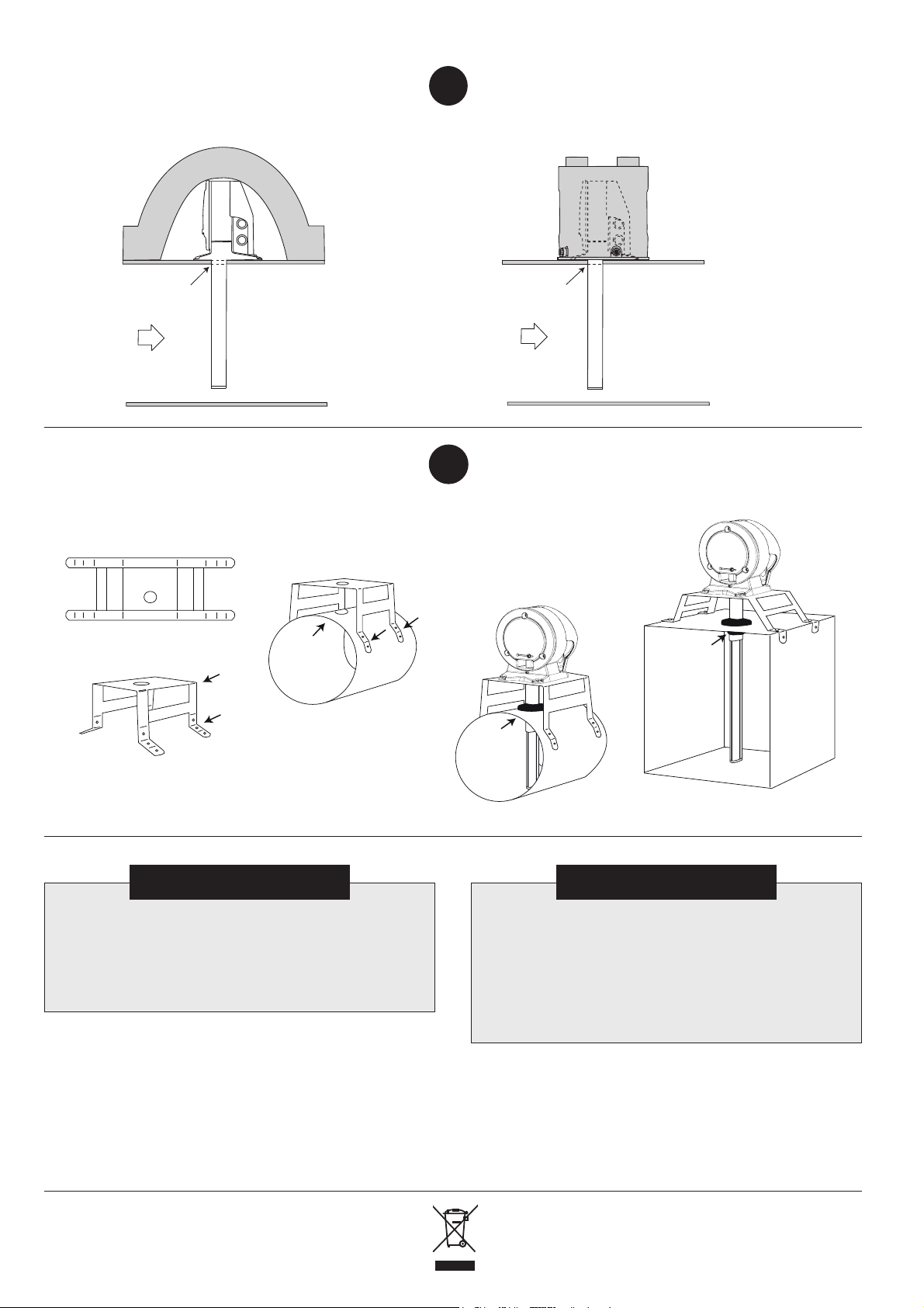
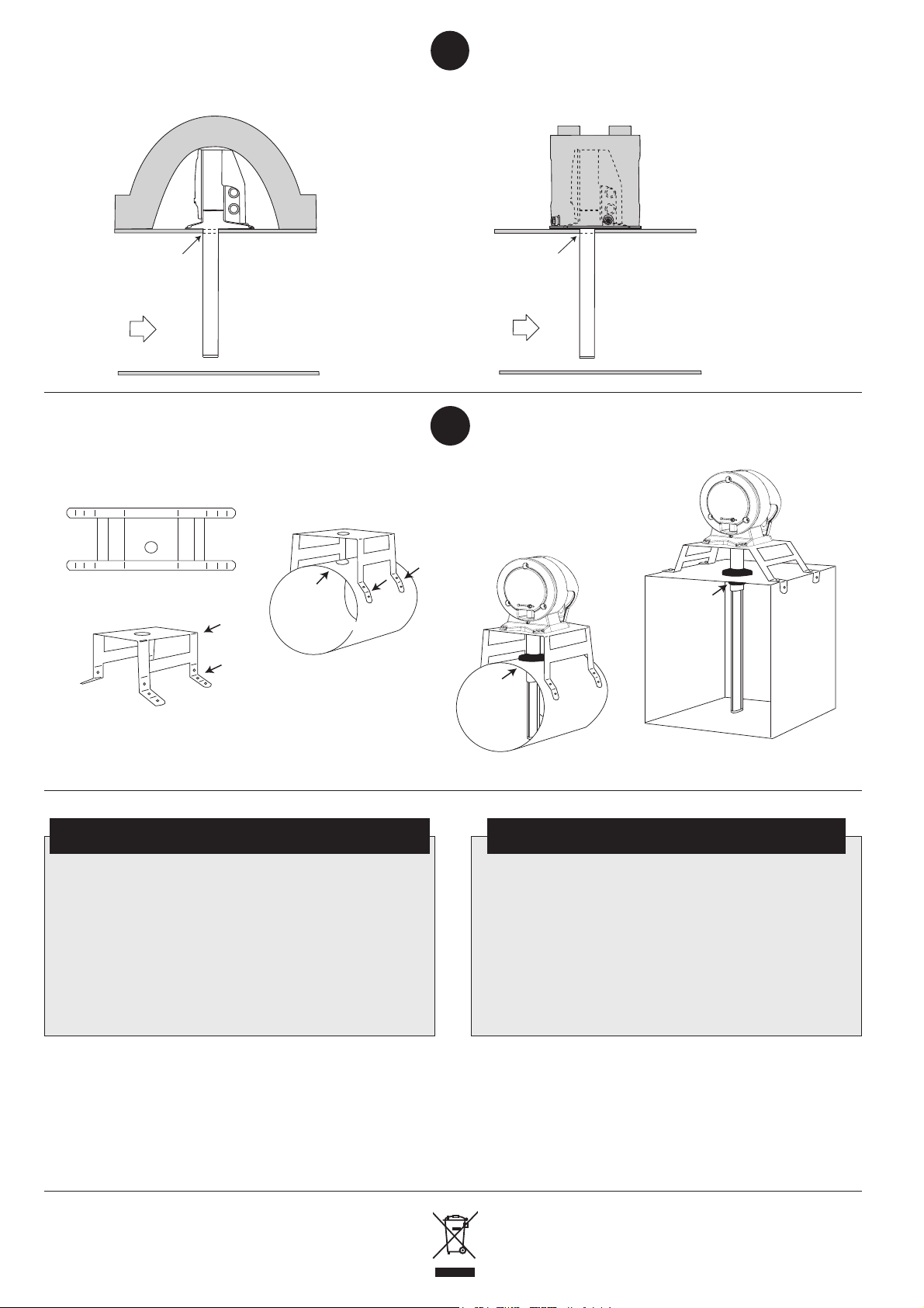
Montering vid risk för kondensproblem,
Monteringsbeslaget levereras plant.
The mounting bracket is supplied flat.
Monteringsbeslaget är lätt att böja/forma så
att det passar runda eller plana kanaler.
The mounting bracket can easily be bent or
shaped to fit circular or rectangular duct.
Håltagning
Ø 51 mm.
Drill a hole
Ø 51 mm.
Fäst beslagets
ben på kanalen.
Fix the bracket
on to the duct.
Rund kanal.
Circular duct.
Gummitätning.
Rubber
gasket.
Isolerad, plan kanal.
Insulated rectangular duct.
Gummitätning.
Rubber
gasket.
t.ex. kallvind eller utomhus.
9
Mounting in places where possible
condensation problems could arise, e.g.
cold attics or outdoor.
Håltagning Ø 38 mm.
Drill a hole Ø 38 mm.
Isolermatta 100-200 mm används för att
täcka hela Uniguarden vid montering
på kallvind. Anvisningsskylt bör monteras.
Use insulation cover of 100-200 mm and
protect the entire Uniguard. A sign should
be used to show location of the detector.
Monteringsbeslag för rund eller
isolerad plan kanal.
Med hjälp av beslaget kan kanaldiametern vara så liten som 100 mm.
10
Håltagning Ø 38 mm.
Drill a hole Ø 38 mm.
Vid montering i kanal utomhus används
isolerande skyddshuv/låda UG-COVER.
For outdoor location use protection
cover e.g. Calectro´s UG-COVER.
Mounting bracket for circular or
insulated rectangular ducts.
Using the bracket the
diameter of the duct can
be as small as 100 mm.
SLUTKONTROLL
• Kontrollera att riktningspilarna pekar i flödesriktningen.
• Kontrollera att pluggen till testhålet sitter i ordentligt.
• Kontrollera att flödesindikatorn visar på flöde (vippar).
• Fullskaleprov med rökgenerator rekommenderas för
kontroll av rökdetektorns funktion.
Felsökning.
Rökdetektorn larmar utan rökpåverkan.
• Rökdetektorn är trasig, smutsig eller placerad så att kondens bildas.
Se punkt 9. Detektorinsatsen behöver bytas ut.
Enligt WEEE (Waste of Electrical and Electronic Equipment)
direktiv, skall produkten när den är förbrukad lämnas separat hos
ett härför avsett insamlingsställe och inte placeras bland osorterat
!
4
avfall. Alternativt returnera den till Calectro för återvinning.
FINAL CHECKS
• Check that the air flow direction arrows have the same direction
as the air flow in the duct.
• Check that the plastic plug of the test hole is properly mounted.
• Check that the flow indicator oscillates ensuring proper air flow
through the detector.
• It is recommended that smoke from a smoke generator is
introduced into the duct to check the detector’s function.
Trouble shooting.
The smoke detector indicates alarm without smoke.
• Smoke detector is faulty, contaminated with dirt or condensation. See
para 9. The detector needs to be replaced.
According to WEEE (Waste of Electrical and Electronic Equipment)
directive, you must at the end of life of the product dispose of it
separately at an appropriate collection point and not place it with
unsorted waste. Alternatively return it to Calectro for recycling.
!
Page 5
DEUTSCH
5 d
h
3 d
h
Beispiel für eine Einbauposition
hinter einer Kanalrichtungsänderung.
Ejemplo de ubicación después de
un cambio de dirección del conducto.
Beachten Sie die pfeilförmige Unterseite, die in Richtung des Luftstroms zu installieren ist.
Tenga presente la forma la flecha en el pie, que deberá instalarse en la dirección del flujo de aire.tion.
Luftzufuhr.
Entrada de aire.
Beispiel für eine Einbauposition
vor einer Luftzufuhr.
Ejemplo de ubicación antes
de una entrada de aire.
Bei großen Temperaturschwankungen, z. B. im Außenbereich
oder in Bereichen, die Außentemperaturen ausgesetzt sind (Dach,
Dachböden) ist der Uniguard-Rauchmelder zu isolieren, siehe Abs. 9
Donde se produzcan grandes variaciones de temperatura como
en ubicaciones exteriores o en áreas sujetas a temperaturas externas
(tejados,áticos), el Uniguard se deberá aislar. Véase el párrafo 9.
d
h
ESPAÑOLA
Montage und Einbauposition.
Installieren Sie den Uniguard-Rauchmelder so, dass die
Richtungspfeile für den Luftstrom (siehe Form der Unterseite des
Uniguard-Rauchmelders oder Oberseite des Gehäuses) in die
Richtung des Luftstroms im Lüftungskanal zeigen. Der UniguardRauchmelder kann an jeder Seite des Kanals installiert werden.
Bitte zu beachten bei Rechteckigen Kanälen: Um eine maximale
Luftprobenabdeckung zu erhalten, installieren Sie den Uniguard auf
der kürzesten Seite eines rechteckigen Kanals.
Wir empfehlen, den Uniguard-Rauchmelder in gleichem Abstand zu
Heiz-, Kühl- oder Feuchtigkeitsgeräten und an ähnlicher Stelle wie
die Luftstromüberwachungen zu installieren.
Ein Abstand in Höhe des dreifachen Kanaldurchmessers ist vor
einer Feuerklappe, einem Filter oder einer Kanalrichtungsänderung
einzuhalten. Hinter diesen Vorrichtungen ist ein Abstand in Höhe
des fünffachen Kanaldurchmessers erforderlich.
Montaje y colocación.
El Uniguard debe instalarse con las flechas de dirección del flujo
de aire (vea la forma del pie de Uniguard o en la parte superior
de la carcasa) de modo que se correspondan con la dirección
del flujo de aire en el conducto. El Uniguard se puede instalar a
cualquier lado del conducto. Nota sobre conductos rectangulares:
Para obtener una cobertura máxima de muestreo de aire, instale
Uniguard en el lado más corto del conducto rectangular.
Recomendamos montar el Uniguard a una distancia igual respecto
a la calefacción, la refrigeración o dispositivos de control de la
humedad, similar a la ubicación para monitores de flujo.
Se debe dejar una distancia de 3 veces el diámetro del conducto
antes de una compuerta, un filtro o un cambio en la dirección del
conducto, y 5 veces el diámetro después de esos dispositivos.
Hydraulischer Durchmesser
RUNDKANAL
CONDUCTO CIRCULAR
d = D
h
Ø D
VIERKANTKANAL
CONDUCTO RECTANGULAR
2xHxB
d =
h
H+B
H
B
Beispiel für die Installation
an Störungsquellen:
- Gebläse
- Feuerklappe
- Schalldämpfer
- Batterie
- Lüftungsanlage
- Kanalbiegungen
- Kanalverzweigungen
- Kanalverjüngung oder erweiterung
h
UG-3
GEBLÄSE
VENTILADOR
h
UG-3
MIN 3xd
MIN 3xd
h
MIN 5xd
MIN 5xd
h
h
UG-3
UG-3
MIN 3xd
UG-3
KANALABZWEIGUNG
BIFURCACIÓN DE CONDUCTO
h
MIN 5xd
h
UG-3
MIN 3xd
MIN 3xd
UG-3
UG-3
MIN 5xd
LÜFTUNGSANLAGE
REGULADOR DE AIRE
UG-3
KANALBIEGUNG
CODO DE CONDUCTO
h
h
RÜCKLUFT / AIRE DE RETORNO
ZULUFT / AIRE ENTRANTE
Diámetro hidráulico
Ejemplo de instalación en
fuentes de interferencias:
- ventilador
- compuerta
- silenciador
- batería
- regulador de aire
- codo de conducto
- bifurcación de conducto
- estrechamiento o expansión de
conducto
5
Page 6
Bohren Sie ein Loch in den Kanal:
• Ohne Montagehalterung: ø 38 mm.
• Mit Montagehalterung und/oder Venturirohr mit
Zusatzgebläse: ø 51 mm (siehe Absatz 10).
Diese Seite NICHT abkürzen!
• Messen Sie den Kanaldurchmesser.
• Kürzen Sie das Rohr bei Bedarf.
• Das Rohr sollte mindestens 90 % des
Kanaldurchmessers durchdringen.
HINWEIS: Siehe Absatz 8.
• Stecken Sie den Rohrverschluss ein.
¡NO corte este extremo!
1
Taladre un orificio en el conducto:
• Sin soporte de montaje, ø 38 mm.
• Con soporte de montaje y/o tubo Venturi con
ventilador auxiliar, ø 51 mm (véase párrafo 10).
2
Rohrverschluss.
Tapón del extremo.
• Mida el diámetro del conducto.
• Si fuera necesario, recorte el tubo.
• El tubo debe penetrar al menos el 90%
de la anchura del conducto.
¡AVISO! Véase párrafo 8.
• Inserte el tapón del extremo.
• Setzen Sie die schwarze Dichtung auf
das Rohr.
• Schieben Sie das Rohr von unten in den
Uniguard-Rauchmelder.
• Befestigen Sie das Rohr mit der
Sicherungsschraube.
• Montieren Sie Rohr und Rauchmelder im
Kanal.
• Sichern Sie die Unterseite des UniguardRauchmelders mit den drei Schrauben
(Positionen mit Pfeilen gekennzeichnet).
HINWEIS - WICHTIG:
Die Richtungspfeile für den Luftstrom
(siehe Form der Unterseite des
Uniguard-Rauchmelders oder Oberseite
des Gehäuses) müssen in die Richtung
des Luftstroms im Lüftungskanal zeigen.
Luftstromanzeige und Rohr mit
Zusatzgebläse*.
Der Uniguard-Rauchmelder verfügt über eine
Anzeige, eine Kunststoff ”Zunge”, die bei
korrektem Einbau durch den Luftstrom nach
außen gebogen wird.
HINWEIS:
Wenn sich die Anzeige nicht bewegt, sollten Sie
den Uniguard-Rauchmelder entweder an einer
anderen Stelle anbringen, oder ein Venturirohr
mit Zusatzgebläse installieren.
Bei der Installation eines Venturirohrs mit
Zusatzgebläse wird immer eine Montagehalterung
verwendet.
* Ein Zusatzgebläserohr ist ein Venturi-Standardrohr mit
einem Zusatzgebläse, das eine separate 24 V AC /
DC-Stromversorgung benötigt.
Sicherungsschraube.
3
Tornillo de fijación.
5
Luftstromanzeige.
Indicador de flu
Venturirohr mit Zusatzgebläse.
Tubo Venturi con ventilador
auxiliar.
Dichtung.
Junta.
4
• Monte la junta negra sobre el tubo.
• Inserte el tubo en la base del Uniguard.
• Asegure el tubo con el tornillo de fijación.
• Monte el tubo y el detector en el conducto.
• Asegure la base de Uniguard con los
3 tornillos en sus posiciones marcadas.
¡NOTA IMPORTANTE!
Las flechas de dirección del flujo de
aire (vea la forma del pie del Uniguard
o en la parte superior de la carcasa)
deben tener la misma dirección que el
flujo de aire en el conducto.
Indicador de flujo y tubo del
ventilador auxiliar*.
El Uniguard se suministra con un indicador, una
lengüeta plástica que , cuando el detector está
correctamente instalado, se dobla hacia afuera
debido al flujo de aire.
¡AVISO!
Si el indicador no se mueve, considere el cambio
a una nueva posición de montaje del Uniguard o
instale un tubo Venturi con ventilador auxiliar.
Si se instala un tubo Venturi con ventilador auxiliar,
siempre se usa un soporte de montaje.
* Un tubo con ventilador auxiliar es un tubo Venturi
estándar que incluye un ventilador de refuerzo.
Requiere una alimentación de CA/CC separada de 24V.
Elektroinstallation.
• Entfernen Sie das Gehäuse, indem Sie den
Schnappverschluss über die Leiterplatte
öffnen.
• Führen Sie das Kabel durch eine der
Klikseal-Kabeldurchführungen. Wenn Sie
einen anderen Kabeldurchführungstyp für
die Kabel verwenden, entfernen Sie die
installierten Kabeldurchführungen, indem Sie
zunächst eine Seite und dann die andere
6
Seite durch die Öffnung schieben (1-2).
(1)
(2)
6
Schnappverschluss.
Cierre a presión.
Rück.
Botón de reinicio.
Instalación eléctrica.
• Para retirar la cubierta que hay sobre la
placa de circuito impreso, abra el cierre
a presión.
• Introduzca el cable a través de uno de los
pasacables Klikseal.
Cuando utilice otro tipo de pasacables,
desmonte los ya instalados presionando
primero un lado a través del orificio y
después el otro (1-2).
Page 7
• Uniguard Superflow verfügt über vier
vormontierte Kabeldurchführungen mit
IP67-Zulassung für Kabeldurchmesser von
4-11 mm, Typ Klikseal (bei der 230 V-Variante
sind es drei Kabeldurchführungen).
HINWEIS: Das Kabel darf nur in eine
Richtung durch den Klikseal gezogen
werden: in den Uniguard-Rauchmelder.
So tauschen Sie ein installiertes Kabel aus:
Schneiden Sie das Kabel außerhalb des
Uniguard-Rauchmelders ab, und ziehen Sie
den Rest von innen heraus.
Klikseal ist gemäß EN50262 zugelassen.
• Schließen Sie die Kabel gemäß Schaltplan an.
UG-3-A4O: 24 V AC/DC.
UG-3-A5O: 230 V AC.
• Das Modell UG-3-A5O werden über
eine neben dem Rauchmelder montierte
Trennvorrichtung mit Strom versorgt.
Diese wird wie folgt gekennzeichnet:
”Trennvorrichtung für Rauchmelder UG-3-A5O”.
Service
alarm
output
Alarm
output
Alarm
output
Power supply
NC
NC
NO
NC
NO
10
C
9
8
• Uniguard Superflow tiene preinstalado
un pasacables en 4 piezas (3 piezas en
la versión de 230 V), homologado IP67,
para cable de 4 a 11 mm de diámetro, tipo
Klikseal.
¡AVISO! El cable solo se debe tirar a
C
7
6
través del Klikseal en una dirección: hacia
el Uniguard.
Para cambiar un cable ya montado: corte
el cable fuera del Uniguard y tire del resto
5
C
4
3
2
1
desde el interior.
Klikseal está aprobado conforme a EN50262.
• Conecte los cables conforme al diagrama de
conexiones.
UG-3-A4O: 24V AC/DC
UG-3-A5O: 230V AC.
• El suministro de alimentación del modelo
UG-3-A5O se hará a través de un dispositivo
desconectador, próximo al detector de humo,
señalado con: “Desconectar dispositivo para
detector de humo UG-3-A5O”.
Rauchmelder-Test.
Überprüfen Sie den Rauchmelder mit dem
Rauchmelder-Tester RDP-300.
• Öffnen Sie die ”Testöffnung”, indem Sie den
Stopfen entfernen, und geben Sie umgehend
einen Sprühstoß des Aerosolsprays hinein.
Bei einer Alarmierung leuchtet die rote LED auf
der Leiterplatte und am Rauchmelder. Bei einem
Servicealarm leuchtet die gelbe LED auf der
Leiterplatte und die grüne LED am Rauchmelder.
• Einheit zurücksetzen durch drücken der
schwarzen Rückstelltaste in der Abdeckung über
der Leiterplatte.
• WICHTIG:
Bringen Sie unbedingt den Stopfen für die
”Testöffnung” wieder an.
Bohren Sie keine Löcher für Schilder usw. in das Gehäuse.
Löcher führen zu Undichtigkeiten und Luftaustritt und beeinträchtigen die Funktionsfähigkeit des Rauchmelders erheblich.
7
Anschließen von Rohren in Kanälen mit
unterschiedlichen Durchmessern.
8
Prueba del detector.
Compruebe el detector con probador de detector
de humo RDP-300.
• Abra el "tapón del orificio de prueba" y eche un
poco de aerosol.
Cuando se genera la alarma, el LED se enciende
en rojo en la placa de circuito impreso y en
el detector. Cuando se produce la alarma de
servicio, el LED se enciende en amarillo en la
placa de circuito impreso y verde en el detector
de humo.
• Para reiniciar, pulse el botón de rearme negro de
la cubierta sobre la placa de circuito impreso.
• ¡IMPORTANTE!
Vuelva a montar el "tapón del orificio de
prueba".
No taladre ningún orificio en la cubierta para fijar letreros, etc. Los orificios originarían fugas de aire y alterarían gravemente el funcionamiento del detector.
Adaptación de tubos en conductos
de distinto diámetro.
Bohren Sie ein Loch
mit Ø 38 mm.
Taladre un orificio
de Ø 38 mm.
Für Kanäle mit einem ø kleiner als 0,6 m verwenden Sie das Rohr 0,6 m.
Für Kanäle mit einem ø zwischen 0,6 m und 1,4 m verwenden Sie das
Rohr 1,5 m.
Für Kanäle mit einem größeren ø als 1,4 m verwenden Sie das Rohr 2,8 m.
Para conductos con un ø de menos de 0,6 m, use el tubo estándar de 0,6 m.
Para conductos con un ø de entre 0,6 m y 1,4 m, use el tubo de 1,5 m.
Para conductos mayores de 1,4 m, use el tubo de 2,8 m.
Max. Durchmesser des Kanals: 0,6 m.
Verwenden Sie das Venturirohr 0,6 m.
Kürzen Sie das Rohr bei Bedarf.
Diámetro máx. del conducto 0,6 m.
Use el tubo Venturi de 0,6 m.
Si fuera necesario, recorte el tubo.
Bohren Sie ein Loch
mit Ø 38 mm.
Taladre un orificio
de Ø 38 mm.
HINWEIS:
Bohren Sie
ein Loch mit
Ø 51 mm.
¡AVISO!
Taladre un
orificio de
Ø 51 mm.
Durchmesser größer als 0,6 m:
Das Venturirohr muss den gesamten Kanal durchdringen.
Diámetro del conducto mayor que 0,6 m.
El tubo Venturi debería penetrar en todo el conducto.
Kürzen Sie das Rohr auf die richtige Länge.
Bringen Sie den Rohrverschluss an.
Setzen Sie die Kunststoffabschlussdichtung ein.
Setzen Sie die Gummidichtung HFU204 ein.
Acortar el tubo a la longitud adecuada.
Insertar el tapón del extremo.
Poner la junta plástica
del extremo.
Poner la junta de goma,
HFU204.
Das Venturirohr darf nicht mehr als max.
30 mm durch die Kanalwand hindurch reichen.
El tubo Venturi no debe sobresalir de la
pared del conducto más de 30 mm.
7
Page 8
Einbau in Bereichen, in denen
Kondensationsprobleme entstehen könnten,
z.B. im Außenbereich oder auf kalten
Dachböden.
9
Montaje en lugares donde podrían surgir
problemas de condensación, como áticos
fríos o exteriores.
Bohren Sie ein Loch
mit Ø 38 mm.
Taladre un orificio
de Ø 38 mm.
Verwenden Sie ein Isolationsgehäuse von
100-200 mm, und schützen Sie das gesamte
Uniguard-Gerät. Ein Schild sollte auf die
Einbauposition des Rauchmelders hinweisen.
Use cubierta de aislamiento de 100-200 mm
y proteja el Uniguard completo. Deberá usar
una señal para indicar la ubicación del detector.
Montagehalterung für Rundkanäle
oder isolierte Vierkantkanäle.
Bei Verwendung der Montagehalterung, kann der
Kanaldurchmesser auf 100 mm beschränkt sein.
Die Montagehalterung wird flach geliefert.
El soporte de montaje se suministra en
forma plana.
Sie können die Montagehalterung durch Biegen oder Formen
ganz einfach an Rund- oder Vierkantkanäle anpassen.
El soporte de montaje se puede doblar o moldear fácilmente
para adaptarse a un conducto circular o rectangular.
Bohren Sie
ein Loch mit
Ø 51 mm.
Taladre on orificio
de Ø 51 mm.
Bohren Sie ein Loch
mit Ø 38 mm.
Taladre un orificio
de Ø 38 mm.
10
Befestigen Sie die
Halterung am Kanal.
Fije el soporte al
conducto.
Gummidichtung.
Junta de
goma.
Rundkanal.
Conducto circular.
Für die Verwendung im Außenbereich
verwenden Sie ein Schutzgehäuse,
z. B. UG-COVER von Calectro.
Para ubicaciones exteriores use
una cubierta de protección, p. ej.,
UG-COVER de Calectro.
Soporte de montaje para conductos
circulares o rectangulares aislados.
Si se utiliza el soporte,
el diámetro del conducto
puede ser tan pequeño
como 100 mm.
Gummidichtung.
Junta de
goma.
Isolierter Viereckkanal.
Conducto rectangular aislado.
ABSCHLIESSENDE PRÜFUNGEN
• Stellen Sie sicher, dass die Richtungspfeile für den Luftstrom
in die Richtung des Luftstroms im Lüftungskanal zeigen.
• Stellen Sie sicher, dass der Plastikstopfen der Testöffnung
korrekt angebracht ist.
• Stellen Sie sicher, dass die Luftstromanzeige vibriert und
so einen ungehinderten Luftstrom durch den Rauchmelder
gewährleistet.
• Wir empfehlen, Rauch von einem Rauchgenerator in
den Kanal einzuleiten, um die Funktionsfähigkeit des
Rauchmelders zu überprüfen.
Fehlerbehebung.
Der Rauchmelder gibt ohne vorhandenen Rauch einen Alarm aus.
• Der Rauchmelder ist fehlerhaft, oder durch Schmutz oder
Kondensation verunreinigt. Siehe Absatz 9. Der Rauchmelder
muss ausgetauscht werden.
Gemäß der WEEE-Richtlinie (Waste of Electrical and Electronic
Equipment) für Elektro- und Elektronik-Altgeräte ist das Produkt am
Ende seiner Lebensdauer separat an einer zulässigen Sammelstelle zu
!
entsorgen. Es darf nicht in den unsortierten Abfällen gegeben werden.
8
Sie können das Produkt auch zum Recycling an Calectro zurückgeben.
COMPROBACIONES FINALES
• Compruebe que las flechas de dirección de flujo de aire
tienen la misma dirección que el flujo de aire en el conducto.
• Compruebe que el tapón de plástico del orificio de prueba
está montado correctamente.
• Compruebe que el indicador de flujo oscila, lo cual garantiza
que existe el flujo de aire apropiado a través del detector.
• Es recomendable introducir humo de un generador de humo
en el conducto para comprobar el funcionamiento
del detector.
Solución de problemas.
El detector de humo dispara una alarma sin que haya humo.
• El detector de humo está averiado, contaminado con suciedad o
condensación. Véase párrafo 9. Es preciso sustituir el detector.
Conforme a la directiva sobre residuos de aparatos eléctricos y
electrónicos (WEEE, Waste of Electrical and Electronic Equipment),
al fi nal de la vida útil del producto deberá desecharlo por separado en
un punto de recogida selectiva apropiado y nunca junto a residuos sin
clasifi car. Opcionalmente, puede devolverlo a Calectro para su reciclaje.
!
 Loading...