


Usage and Assembly Instructions
Instructions #1037447
Product #795234
Revision C
Rear Fork (Buttstock)
Rails
Rail Brackets
Arm Rotation
Friction Knobs
Hook-and-loop Straps
Front Fork (Forend)
Rear Fork Lock Knob
Rail Lock Knob
Tilt Friction Knob
Rail Extension Locks
Front Fork Lock Knob
Swing-Arm Post
Backpack Strap
Clamp Lock Knob
Chair Leg Assembly
1
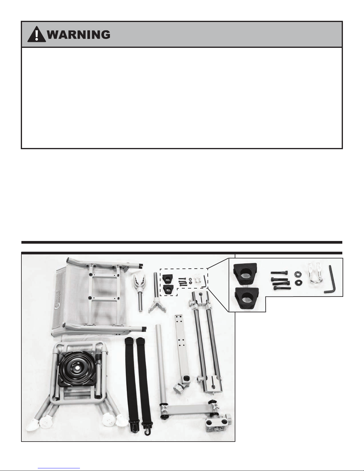
IMPORTANT SAFETY INFORMATION
SHOOTER MUST WEIGH BETWEEN 50LBS and 300LBS FOR SAFE USAGE
DO NOT STAND UP OR LEAVE CHAIR UNATTENDED WHILE GUN IS IN FORKS. THE
CHANGE IN BALANCE COULD CAUSE THE CHAIR TO TIP.
USE CAUTION TO AVOID TIPPING WHEN ON UNEVEN TERRAIN, WHEN LEANING
BACK, AND WHEN USING A HIGH-RECOILING RIFLE.
THE DEADSHOT CHAIRPOD SHOULD ONLY BE USED WHEN ALL FOUR FEET ARE
FIRMLY IN CONTACT WITH THE GROUND. IT IS NOT INTENDED TO BE USED IN A
TREESTAND OR ELEVATED PLATFORM
®
Thank you for purchasing a Caldwell
assembled and will only require a couple steps to assemble using the included tool. Please read these
instructions completely and become familiar with the product and its functions before attempting to
use. Improper setup and use could result in damage to the product, injury or even death. Safe operation
of this product is the responsibility of the user.
This product may or may not be compatible with all rearms/crossbows. Conrm t prior to use in
hunting situations. Be mindful of crossbow limb clearance both in their cocked and discharged positions.
Throughout these instructions, the word “weapon” is used to universally describe ries, shotguns,
crossbows, etc.
DeadShot® ChairPod. Your DeadShot ChairPod is almost completely
CONTENTS
A
G
B
H
F
E
D
C
Parts Identication of Box Content:
A. Chair Seat Assembly
B. Chair Leg Assembly
C. Swing-Arm Assembly
D. Clamp Bar - 1025799
E. Rail Assembly - 1038038
F. Front Fork - 1038281
G. Rear Fork - 1038293
H. Backpack Straps - 1037896
Hardware Pack
I. 1 - Backpack Strap Hook - 1037184
J. 2 - Rubber Bar Holders - 1036905
K. 4 - M6x25 Cap Screws - 1035240
L. 2 - M6 Washers - 1005215
M. 1 - Hex Key
K
J
L
I
M
2

ASSEMBLY AND SETUP INSTRUCTIONS
1. Pull the Seat Leg Assembly out of the Seat Chair Assembly and set it aside for the moment. Photo 1
2. Pass two of the M6 Screws through the Backpack Strap Hook as shown. Photo 2
Photo 1 Photo 2 Photo 3a
Photo 3b
Photo 3c
3. Using the remaining M6 Screws and Washers and the Backpack Strap Hook, attach the Clamp Bar to the Chair
Seat Assembly as shown. Then rmly tighten the screws using the hex key provided. Photo 3a-d
Photo 3d
NOTE: There are two sets of holes in the clamp bar, most
users will nd the rear set of holes provides the
most comfortable t, but the other set can be
used to move the Swing-Arm assembly closer to
the shooter.
NOTE: The clamp can be assembled for either right or
left-handed shooters. For a right-handed shooter,
the knob should face to the Left, as seen when
sitting in the chair. Photo 3d
Chair mesh removed for clarity
3

4. Using a screwdriver, remove the 4 screws in the Chair Seat Assembly shown. Then using the same screws and
washers, attach the two Rubber Bar Holders as shown. Photo 4a and b
Photo 4a Photo 4b
NOTE: These screws only need to be lightly tightened. Over-tightening the screws could
damage the Bar Holder. If having trouble aligning screw holes pull Rubber Bar Holders.
5. Remove the 4 Cap Screws from the Bottom of the Chair Seat Assembly, and using the same screws, attach the
Leg Assembly as shown. Then rmly tighten the screws using the hex key provided. Photo 5a and b
Photo 5a
Photo 5b
Photo 6a
6. The Backpack straps can now be installed. To do this, pass the looped end under the cross bar on the back
of the chair. Wrapping the clip end around the bar, pull it through the loop and pull it tightly as shown. Then
attach the clip to the Hook assembled to the cross bar. Photo 6a-c
Photo 6b
Photo 6c
4
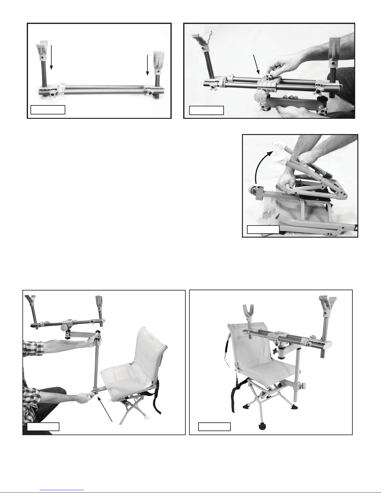
Front Fork
Rear Fork
Rail Clamp
Photo 7
Photo 8
7. Slide the Front and Rear Forks into the Rail Assembly as shown,
taking careful note of the orientation of each part. Photo 7
8. Unscrew the top Knob on the Swing-Arm Assembly and remove
the top half of the Rail Clamp. Install the Rail Assembly as shown
and then replace the top of the Clamp and re-tighten the knob.
Photo 8
9. Unfold the Legs of the Chair by pushing rmly on the frame
and pulling on the cross-bar between the legs as shown. Photo 9
Photo 9
10. Loosen the Clamp Lock Knob, and slide the post of the Swing-Arm Assembly into it. When the
Shooting Rail assembly is at the desired height, rmly tighten the knob to lock it into place. Photo 10
Photo 10
Clamp Lock Knob
11. The DeadShot ChairPod is now fully assembled. Please read and understand the Usage instructions fully
before use. Photo 11
Photo 11
5

USAGE INSTRUCTIONS
Please refer to the photo on Page 1 to identify the parts and knobs of the ChairPod
1. Unfold the Legs of the Chair by pushing rmly on the frame and pulling on the cross-bar between the legs
2. Loosen the Clamp Lock Knob and insert the Swing Arm Post and Rail Assembly. Position the height of
Shooting Rail Assembly such that the Rear Fork is a little below shoulder level and tighten the Clamp Knob
Check that the Swing-Arm Post is rmly clamped before use. Do not adjust the post too
high so that it is only partially secured by the clamp.
Do not adjust height with weapon resting in forks
3. Loosen both Fork Lock Knobs and ip the Front and Rear Forks upright. The height of each Fork can be
adjusted up or down to t the geometry of your weapon. Once positioned to the desired height, tighten the
Fork Lock Knobs to hold Forks in the desired vertical position.
4. Adjust distance between the Forks by disengaging the Rail Extension Locks and sliding the Rails in or out as
needed to t your weapon. Engage the Locks when adjustment is complete.
5. Adjust the position of Rail Assembly within the Rail
Brackets so the weapon’s center of gravity will be placed
over the center swivel. This will help the weapon maintain
balance when placed in the Forks. Photo12
Rail Extension Locks
6. Tighten the Tilt Tension Knob and Rotation Tension Knobs
on the Arm so they are snug and provide resistance to
Rail Lock Knob
rotation. Make sure there is adequate friction at each joint
to prevent the weapon from rotating or moving into an
unsafe position.
7. Place weapon into the Forks. If further adjustments of
Forks or Rail Assembly are needed for proper shooting
Tilt Friction Knob
form, remove weapon from rest before making
adjustments. Once all adjustments have been made, verify
all lock knobs are securely tightened.
NOTE: Remove Swing-Arm Assembly when entering or exiting chair for ease of use.
Photo 12
6

DISASSEMBLY FOR TRANSPORTATION
1. Loosen the Clamp Lock Knob and Remove the Entire Shooting Rest Assembly from the Chair.
2. Fold the forks down and slide the rails to their shortest position, then re-tighten.
3. Loosen the Top Clamp Knob so that the rails can slide easily.
4. Fold the backrest of the Chair down and then fold the legs in, securing the legs with the hook-and-loop
straps on the back of the chair as shown. Photo 13
Hook-and-loop
strap
Photo 13
5. Finally, with the Rail Assembly oriented as shown, slide the bar through the Rubber Bar Holders until the Rail
is secured by the rubber Cradle on the back of the Chair as shown. Photo 14a and b
Cradle
Photo 14a
Rubber Bar
Holders
Photo 14b
7

MAINTENANCE
1. Periodically check mounting bolts, knobs and fasteners for adequate tightness and function.
2. Application of a rust preventative and/or grease may be needed on exposed threads around
Knobs if extended periods of outdoor exposure are anticipated.
3. If play can be felt in any of joints, the bearing set may need adjustment. Remove rubber plug from bearing
cap and tighten bearing screw with 5 mm hex key. Photo 15a-c
NOTE: Over-tightening the bearing set can result in damage to the bearing races and will cause
reduced performance. Only tighten a little at a time and test often until play is eliminated.
Photo 15a
Photo 15b Photo 15c
REMOVE RUBBER PLUG FROM
BEARING CAP
TIGHTEN BEARING SCREW
WITH 5MM HEX KEY
8
 Loading...