

PARADISE SERIES
PORTABLE SPA
OWNER’S MANUAL
GENEVA • NIAGARA
HAWAIIAN • TAHITIAN
MARTINIQUE • KAUAI
QUALITY SPAS
AND GAZEBOS SINCE 1976.

TABLE OF CONTENTS
SET UP AND INSTALLATION
• Site selection and preparation . . . . . . . . . . . . . . . . . .3
• Equipment compartment access . . . . . . . . . . . . . . . .3
• Electrical installation . . . . . . . . . . . . . . . . . . . . . . . . .4
MAINTENANCE
• Important maintenance procedures . . . . . . . . . . . . .10
• Equipment compartment illustration . . . . . . . . . . . . .11
• Filter removal and maintenance . . . . . . . . . . . . . . . .12
• Spa light colored lens installation . . . . . . . . . . . . . . .12
• Spa light bulb replacement . . . . . . . . . . . . . . . . . . .12
• Power Diver ter maintenance . . . . . . . . . . . . . . . . . .12
• Spa cover care . . . . . . . . . . . . . . . . . . . . . . . . . . . .13
• Non-operation in a cold climate . . . . . . . . . . . . . . . .13
• Winterizing your spa . . . . . . . . . . . . . . . . . . . . . .13-14
• Draining your spa . . . . . . . . . . . . . . . . . . . . . . . . . .14
BALANCING THE SPA W A TER
• Balancing your spa water (first time) . . . . . . . . . . . .15
• 3-day-a-week spa care program . . . . . . . . . . . . . . .15
SP A TROUBLESHOO TING
• Basic Troubleshooting . . . . . . . . . . . . . . . . . . . . . . .18
• LCD messages . . . . . . . . . . . . . . . . . . . . . . . . . . . .19
WATER MAINTENANCE
• Water pur ification with Ozone . . . . . . . . . . . . . . . . .16
• Alkalinity Table . . . . . . . . . . . . . . . . . . . . . . . . . . . .16
• pH Level Table . . . . . . . . . . . . . . . . . . . . . . . . . . . . .16
• Sanitizer Level Table . . . . . . . . . . . . . . . . . . . . . . . .16
SP A W ATER TROUBLESHOO TING . . . . . . . . . . . . . .17
SPA SPECIFICATIONS . . . . . . . . . . . . . . . . . .Back cover
START-UP INSTRUCTIONS
• Installing the spa cover . . . . . . . . . . . . . . . . . . . . . . .6
• Top view-features illustration . . . . . . . . . . . . . . . . . . .6
CUSTOMIZING Y OUR MASSA GE
• Power Diver ters, Air controls & Hydro jets . . . . . . . . .7
• Air Jets . . . . . . . . . . . . . . . . . . . . . . . . . . . . . . . . . . .7
OPERATION
• Spa-side controls . . . . . . . . . . . . . . . . . . . . . . . . . . .8
• Touch pad controls . . . . . . . . . . . . . . . . . . . . . . . . . .8
• Standard or Economy mode . . . . . . . . . . . . . . . . . . .9
• Skim/Filter cycles . . . . . . . . . . . . . . . . . . . . . . . . . . .9
• Changing Skim/Filter cycles . . . . . . . . . . . . . . . . . . .9
IMPORTANT SERVICE INFORMATION . . . . . . . . . . .1
IMPORTANT SAFETY INSTRUCTIONS . . . . . . . . . . .2
OPTIONS
• Pure Water Ozone System . . . . . . . . . . . . . . . . . . .19
IMPORTANT SERVICE INFORMATION
Dealer:
Address:
Phone:
Date of purchase:
Electrician:
Installation date:
Spa serial #:
Model #:
Optional equipment:
Congratulations on your new ownership of a quality
Caldera portable spa.
This manual will help you with ever y aspect of operation
as well as provide helpful information on how to care for
your spa.With proper maintenance, your Caldera spa
will provide you with many years of relaxation and
dependable service.
If you have any questions not addressed in this manual, call
your Caldera dealer and he or she will be happy to assist y ou.
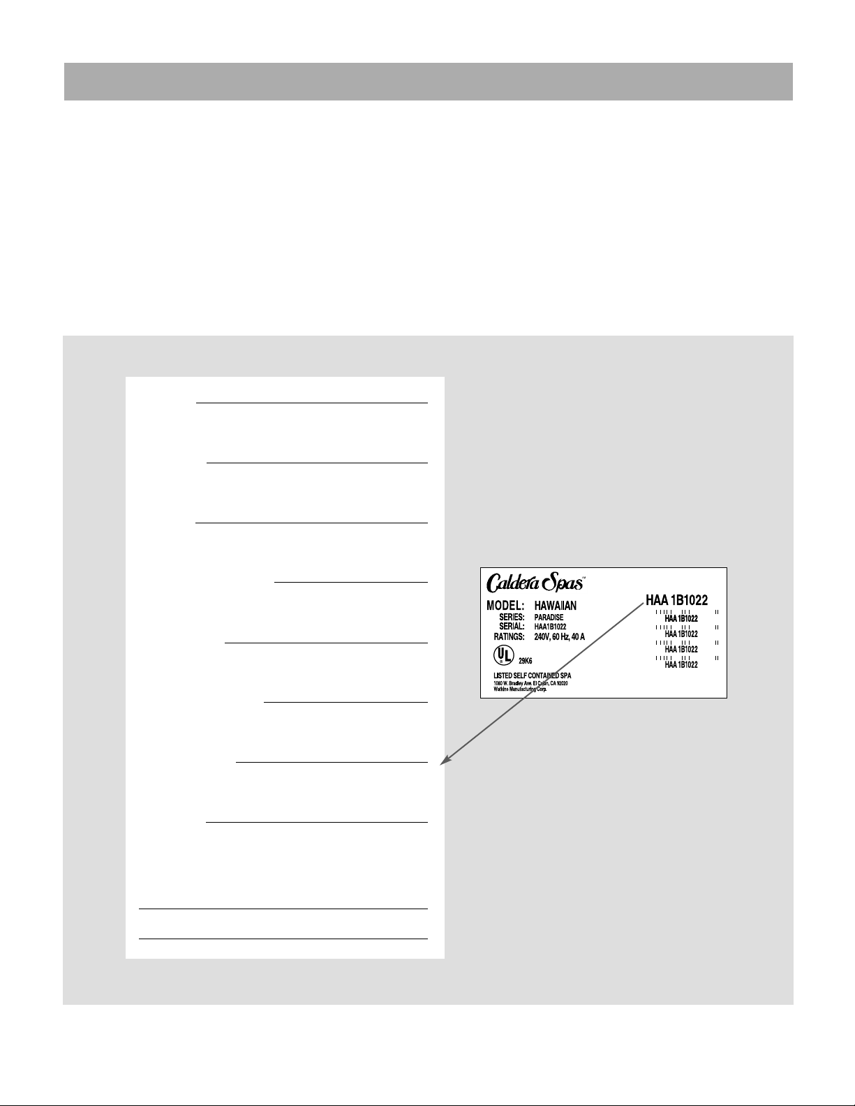
Pictured below are the Caldera Data labels that are located in the spa equipment compartment. Locate and read
these labels, then fill out the blanks below with the corresponding information.
If replacement parts are needed, it is impor tant that you
have the complete Data Label infor mation for your dealer or service organization.
Retain this manual for future reference. Please have the
information below readily available if you need to contact your Caldera dealer for service or repair.
Page 1
NOTE: This is an example. Your spa’s
label will contain different information.

IMPORTANT SAFETY INSTRUCTIONS
READ AND FOLLOW ALL INSTRUCTIONS
1. DANGER - RISK OF ACCIDENTAL DROWNING.
Extreme caution must be exercised to prevent unauthorized access by children. To avoid accidents, ensure that
children cannot use this spa unless they are under adult
supervision at all times.
2. WARNING - To reduce the risk of injury:
A. A bonding lug has been provided on the outside of the
Control Module electrical control box. This lug permits the
connection of No. 6 AWG solid copper bonding conductor
between the Control Module and all other electrical equipment and exposed metal in the vicinity, as may be needed to comply with local regulations.
B. The suction fittings in this spa are sized to match the
specific water flow created by the pump. Should the need
arise to replace the drain-suction fittings or the pump, be
sure that the flow rates are compatible. Never replace a
suction fitting with one rated less than the flow rate
marked on the original suction fitting. Never remove, or
alter in any way, the covers on the drain-suction fittings in
the spa. Never operate the spa if the covers on the drainsuction fitting are broken or missing.
C. To eliminate the risk of electr ical shock install the spa
at least 5 feet (1.5m) from all metal surfaces. (A spa may
be installed within 5 feet of metal surfaces if each metal
surface is permanently connected by a minimum No. 6
AWG solid copper conductor attached to the wire connector on the terminal box that is provided for this purpose.
D. Do not permit any electrical appliances such as a light,
telephone, radio or television within 5 feet (1.5m) of the
spa.
E. The spa must only be hard wired to a supply circuit
that is protected by a ground fault circuit interrupter
(GFCI). Such a GFCI is required by most building codes,
should be provided by the installer and must be tested
before each use. Consult GFCI manufacturers instructions for correct testing and operation.
F.
The water in a spa should never exceed 40 degrees C
(1040F).
Water temperatures between 1000F and 1040F
are considered safe for a healthy adult. Lower water temperatures are recommended for extended use (exceeding
10-15 minutes) and for young children.
G. Since excessive water temperatures have a high
potential for causing fetal damage during the early months
of pregnancy, pregnant or possibly pregnant women
should limit spa temperatures to 100
0
F.
H. Before entering the spa, the user should measure the
water temperature with an accurate thermometer since
the tolerance of water temperature regulating devices ma y
vary as much as ± 5 degrees.
I. The use of alcohol, drugs, or medication before or during spa use may lead to unconsciousness with the possibility of drowning.
J. Persons suffering from obesity or with a medical history of hear t disease, low or high blood pressure, circulatory system problems or diabetes should consult a physician before using a spa.
K. Persons using medication should consult a physician
before using a spa since some medications may induce
drowsiness while other medications may affect heart rate,
blood pressure and circulation.
L. Because occasional users of the spa may not be
aware of all the potential risks associated with spa usage,
they should be made aware of these important safety
instructions.
M. The electrical supply for this product must include a
suitably rated switch or circuit breaker to open all
ungrounded supply conductors to comply with the
National Electrical Codes. The disconnection means
must be within sight and readily accessible to the spa
occupants but installed at least 5 feet (1.5m) from the spa
water. (For permanently connected units not provided
with an integral disconnecting means).
N. All units must be installed to provide drainage of compartment for electrical components.
O. Be sure that water always flows freely from the
hydrotherapy jets within the spa. Any blockage or restriction of this water flow by persons or objects may damage
system components, create an electrical shock hazard,
and/or cause water damage to the surrounding area.
P. To avoid damage to the pump and heater, the spa must
never be operated unless the spa is filled with water.
SAVE THESE INSTRUCTIONS
Page 2
SET UP AND INSTALLATION
30 INCHES MINIMUM
EQUIPMENT ACCESS
AREA
EQUIPMENT COMPARTMENT ACCESS
When considering an installation site, always allow for a
minimum access space of 30 inches in front of the equipment compartment of the spa. This provides adequate
clearance for future service if necessary.
If accessory items will be installed on or around the spa
(gazebos, steps or planters), allow for additional space
around the spa’s perimeter.
Please note: Some cities and counties may require
a permit for installation of electrical circuits or the
construction of exterior structures (decks and gazebos). In addition, some counties may require permits for the installation of a portable spa. Check
your local codes for compliance.
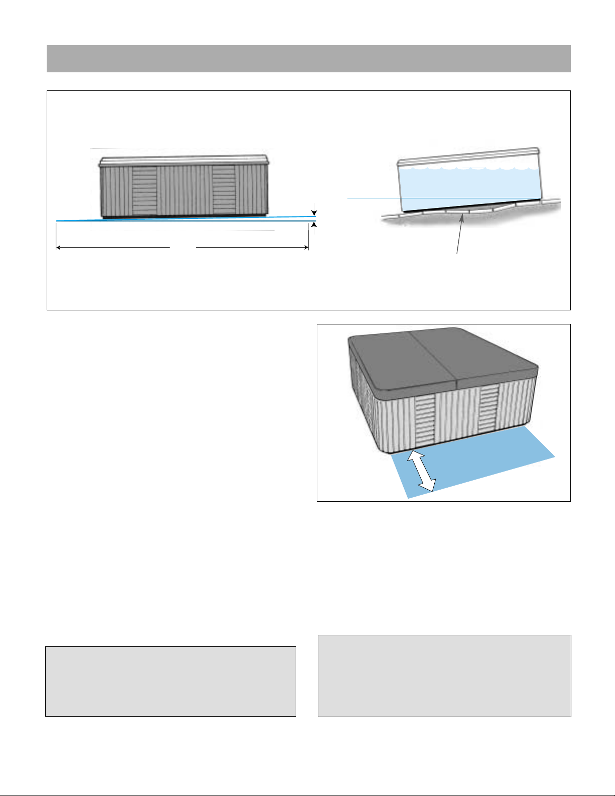
SITE SELECTION
In order for your spa to function properly, it must be placed
on a SMOOTH, LEVEL, SELF-DRAINING SURFACE.
Concrete sloped at 1 inch per 10 feet is preferred so that
rain water and water spillover will run off and not puddle
underneath the spa (water under the spa for long periods of time may cause the wood to deteriorate). Other
options are brick, stepping stone or blocks.
It is important to note that soft surfaces, even
when stepping stones are used to evenly distribute the weight of the spa, will have a tendency to
settle, thus resulting in an unleveled spa.
INSTALLATION ON A WOOD DECK - Wood decking
requires that the deck must be constructed to support at least 80 pounds per square foot. Individual
spa weight per square foot will vary. Refer to a
licensed contractor for proper structural support.
Refer to the SPA SPECIFICATIONS table on the
back cover for spa dry weight and spa weight
with water.
Please Note: Placing the spa on grass or dirt may
increase the amount of debris which is inadvertently brought into the spa water and may cause harm
to your equipment as well as the spa surface, and is
not covered under warranty.
Slope 1 inch per 10 ft.
for proper drainage.
1 inch
10 ft.
Stepping stones or brick
may settle causing the
spa to be unlevel.
Page 3
LEVEL
M
I
N
I
M
S
3
M
P
I
U
Q
E
E
H
C
N
I
0
C
C
A
T
N
E
A
E
R
A
M
U
S
S
E
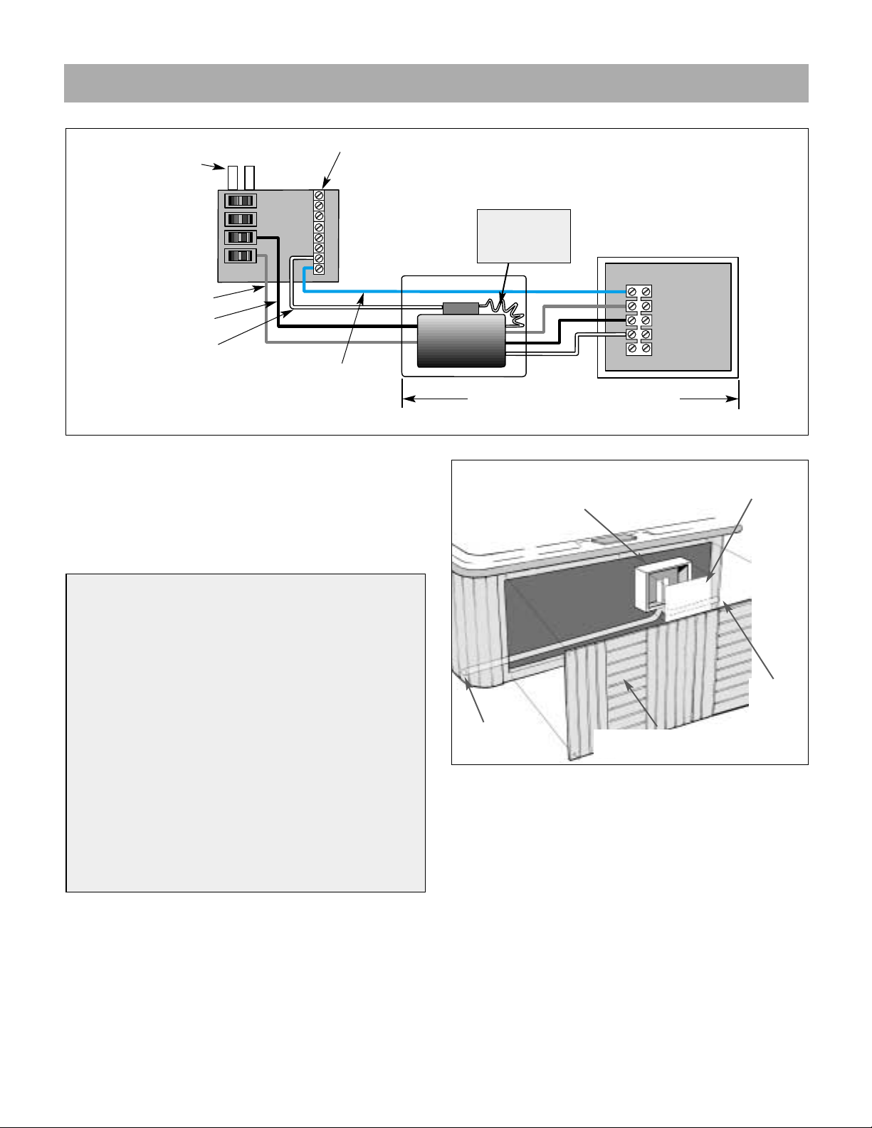
ELECTRICAL INSTALLATION
240V WIRING SCHEMATIC DIAGRAM
POWER CONNECTION To connect power to the spa,
refer to “240 VOLT WIRING SCHEMATIC DIAGRAM” and
“POWER CONNECTION ACCESS” illustrations above,
then proceed with the following steps:
1. Remove the screws securing the equipment compartment door and remove the door.
2. Remove the screws securing the Control Module wiring
access panel and remove the panel to allow access to the
input power wiring.
NOTE:The 240V wiring diagram is located on the inside of
the Control Module access door.
Inputs from
transformer
Neutral/Ground Bar
Green (Ground)
Red (Hot)
Black (Hot)
White (Neutral)
White (Neutral)
(Panel Neutral)
(Pigtail)
Red
Black
White
GFCI should be located more than
5 ft. and less than 50 ft. from the spa.
Check your local codes.
The Control Module requires a 6 AWG copper, four-wire
electrical service (Line 1, Line 2, Neutral and Ground),
and requires a minimum supply conductor ampacity of
50 amperes. Failure to connect a neutral line will cause
the Control Module to malfunction and will void the
Control Module warranty.
NOTE: The 240V wiring diagram is
located on the back of the Control
Module access panel.
Page 4
240 VOLT INSTALLATION
Your spa contains a Control Module designed to operate at
240V, 60Hz. Installation of a 50 amp. dedicated circuit is
required.The Control Module must be hard wired directly to
a supply circuit that is protected by a Ground Fault Circuit
Interrupter (GFCI).
IMPORTANT NOTE: All electrical connections to the
Control Module must be accomplished by a qualified
electrician in accordance with the National Electrical
Code and in accordance with any local electrical codes
in effect at the time and place of installation.
All electrical connections must be made in accordance with
the wiring information contained in this manual and on the
back of the field wiring access panel of the Control Module.
For all permanently connected units not provided with
integral disconnecting means: The electrical supply for
this product must include a suitable rated switch or circuit breaker to open all ungrounded supply conductors to
comply with local and national Electrical Codes. The disconnecting means must be within sight, and readily
accessible to the user of the spa, but installed at least 5
feet (1.5m) from the spa.
POWER CONNECTION ACCESS
240V WIRING
ACCESS
CONTROL MODULE
WIRING ACCESS PANEL
EQUIPMENT COMPARTMENT
DOOR
CONTROL MODULE
240V
WIRING
ACCESS (2)
OPENINGS ON
RIGHT& LEFT
HAND SIDE
HOT
AB
Circuit Breaker
Panel (House)
G.F.C.I.
Spa Control Module
TB 1
5
4
3
2
1
Page 5
START-UP INSTRUCTIONS
Once the spa is placed on a proper foundation and connected to the appropriate electrical service, the spa may
be filled and made ready for use. For best results, read
each step in its entirety before proceeding with that step.
1. PREPARE SPA FOR FILLING
• Clear all debris from the spa.
• Although the spa shell has been polished at the factory, you may want to treat it with a specially formulated spa cleaner and wax available from your dealer
prior to filling it for the first time.
• Before filling your spa for the first time, refer to the
“EQUIPMENT COMPARTMENT” illustration on page 11 and
perform the following procedures to ensure proper operation:
• Remove the equipment compartment door.
• Check all pump and heater unions to ensure that
they are hand-tight.
• Check that all knife valv es are in the open position.
• Install pump drain plugs, if necessary.
2. FILL THE SPA
•Remove the skimmer basket and weir - see page 12.
•Inser t the end of a garden hose into the filter canister
and begin filling the spa.
•Stop filling when the water level is approximately one
inch above the highest jet.
•Reinstall the skimmer basket and weir.
3.TURN ON POWER
Turn on power to the spa at the home’s circuit breaker,
Ground Fault Circuit Interrupter (GFCI) and any other
switching devices installed by your electrician. When
power is on, the spa’s LCD screen will display information.
4. ACTIVATE JETS
• Set all air controls to the “Max” position to help you see
which jets are being activated. See illustration on page 6.
• Press the “Hydro Jets 1” touch pad on the control
panel twice to turn on the high speed of the dualspeed pump - see “SPA SIDE CONTROLS” illustration
on page 8.
• You should be able to feel a steady stream of water
from at least some of the jets. If not, refer to the
instructions for priming the pump in the SPA TROUBLESHOOTING section in the back of this manual.
• Press “Hydro Jets 1” again to turn off, then press
“Hydro Jets 2” to turn on the single-speed pump. Once
a steady flow of water is detected from some of the jets,
press this touch pad once more.
5. ADD START-UP CHEMICALS
Add the spa water chemicals as directed by your Caldera
dealer, b y the instructions contained in your spa chemical
kit or in the section titled “BALANCING THE SPA WATER”
on page 15.
6. SET TEMPERATURE
Your spa has been pre-set to automatically achieve a
water temperature of 100
0
F, which is the temperature typically preferred for comf ortable spa enjo yment. If you prefer a different temperature, press either the or
touch pad to display the temperature which has
been set. Then, each time either of these pads is pressed
again (within five seconds), the set temperature will
increase or decrease depending on which pad is
pressed.
• The maximum temperature for which the spa can be
set is 1040F and the minimum is 800F.
7. SET SPA TO HEAT
• Make certain the controls are set to operate in the
“STANDARD” operating mode. That is, if the LCD
shows “ECON” flashing alternately with the water temperature, press the touch pad to switch to
“STANDARD”mode. This allows the heater to run continuously until the set temperature is achieved. (See
“STANDARD OR ECONOMY MODE” on page 9.)
• The time required for initial heat-up will vary depending on the temperature of the fill water and the size of
the spa. You may expect a temperature rise of approximately 4 to 6 degrees per hour for larger spas and
about 8 to 10 degrees per hour for small spas.
DANGER. RISK OF INJURY. Always check the water
temperature carefully before entering the spa.
NOTE: Never fill your spa with water from a water
softener. Its corrosive effects will damage your spa’s
components.
IMPORTANT - Do not activate power until the spa
is filled. To avoid damage to the spa’s equipment,
the pumps must never be operated unless the spa
is filled with water.
Warm Time
Light
Warm Time
Light
Warm Time
Light
(During winter months, the pumps’ drain plugs are removed
to prevent possible freeze damage during shipping and
storage. If this is the case with your spa, there will be a
notice to this efffect taped to the front of the spa’s control
box and the drain plugs will be in the plastic bag that
includes the owner’s manual.)
(Clear, plastic tubing has been factory-installed around the
shaft of each of these valves to keep them from inadver-
tently closing. This step is a precautionary measure to
ensure that these valves have not closed during shipping.)
Page 6
9. INSTALL THE SPA COVER
• Place the cover squarely on the spa.
• Position the tie-down locks included with your cover
on the side of the spa so that they are easily reached
by the cover tie-down straps. Allow for about 1/2” to
3/4” slack in the straps to make it easy to insert straps
into locks and to compensate for vinyl shrinkage in
cold weather.
• Attach the locks with the screws provided and insert
the cover tie-down straps into the locks.
Keeping the cover in place any time the spa is not in
use will reduce the amount of time the heater operates, thereby minimizing operating costs.
DANGER. RISK OF INJURY.
• Never leave a spa uncovered or unattended.
• Never leave a spa cover unlocked.
• Do not stand, sit or lie on the cover.
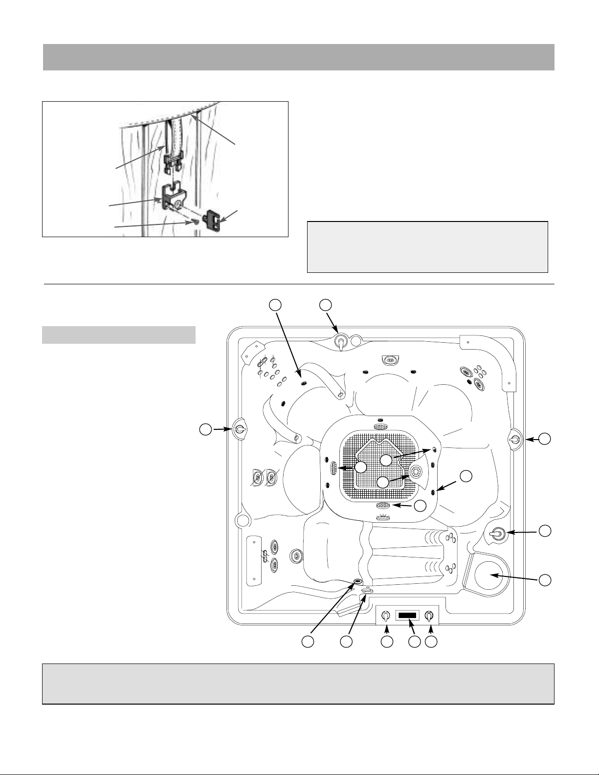
COVER INSTALLATION
TIE-DOWN STRAP
LOCK
COVER
KEY
SCREW (2)
1. Power diverter
2. Air control
3. Air jets
4. Filter compartment
5. Spa-side control panel
6. Temperature sensor
7. Spa light
8. Euphoria jet
9. Drain/suction fitting
10. Ozone
TOP VIEW - FEATURES
GENEVA MODEL SHOWN.
FEATURES AND LOCATIONS MAY VARY IN OTHER MODELS.
START-UP INSTRUCTIONS
1
1
2
2
22
3
4
56
2
3
7
8
9
10

CUSTOMIZING YOUR MASSAGE
Page 7
Your Caldera spa offers numerous ways for you to customize your massage experience. Experimentation is the
best way to find what feels best to you. Tr y sitting in different seats, adjusting the Power Diverters, air controls
and jet nozzles and turning each pump on or off.
POWER DIVERTERS
One Pow er Diverter is standard on your spa, another is optional equipment. These allow you to direct the flow of water from
the pumps to various combinations of jets.
The functions of these Pow er Div erters can best be learned by
experimentation as follows:
1. Set all air controls to the “MAX” position.
2. Turn on the high speed of both pumps.
3. Note the labels on the Power Diver ters and turn the
handles and see which groups of jets are affected.
(Note that you can adjust the Power Diverters to any
position between the two possible extremes to achieve
the jet pressure that feels best to you.)
AIR CONTROLS
Each jet system has its own air control. These allow you
to change the power of the jets by regulating the amount
of air that is mixed with the water coming out of the jets.
HYDRO JETS
Magna Jets - These jets allow you to re-direct the jet stream by
changing the position of the nozzle.
MagnaSsage Jets - These jets provide a rotating massage pattern.
The nozzles in the Magna jets and the MagnaSsage jets
are interchangeable. To remove a MagnaSsage rotating
nozzle, simply grasp it and pull straight out. To install,
align and push straight in. the nozzle will snap into place.
To remove or install a standard Magna jet nozzle, rotate
the tabs on either side of the nozzle. Additional
MagnaSsage rotating nozzles and dual-port nozzles are
available from your Caldera dealer.
Both the Magna and MagnaSsage jets allow you to regulate the force of the massage. Rotate the fascia ring
clockwise to reduce the force or counter-clockwise to
increase the force. Notice that tur ing off the flow to some
jets increases the flow to the other jets. To avoid damage
to your spa’s plumbing and components, do not turn off
more than half of these jets at the same time.
Euro and Euro-Pulse Jets
- The small euro jets deliv er a direct,
precision massage. Many of these jets feature a special insert
that creates a soft, pulsating, rotary massage. The roto jet cap
assemblies may be removed if you want a more powerful,
direct massage in a particular location. To do this, gently pry
around the outside edge of the cap assembly with a table knif e,
screwdriver or similar tool. If you desire, you may install a roto
jet cap removed from one jet onto a standard euro jet simply
by snapping the assembly into place. You may purchase additional roto jet assemblies from your Caldera dealer.
AIR JETS
The Air jet system consists of a 1 HP Air pump and 10 Air
jets. At the beginning of each skim/filter cycle, the Air jets
will operate for 30 seconds to clean out the air channel.
TIP: Turn both pumps on high speed and position the
Power Diver ters to “Combo”. Then experiment with
each of the air controls to see their effect.
IMPORTANT: Your spa is not designed to provide full
power to all jets when the Power Diverters are in the
“Combo” position. However , with the Power Diverter in
this position, you may increase the power to selected
jets by rotating the face of the Magna and
MagnaSsage jets to close the ones that are not in use.
Position 1 - The full
flow is directed to one
series of jets.
Position 2 - The flow
is shared between two
or more series of jets.
Position 3 - The full
flow is directed to a
second series of jets.
MAXMAX
MINMIN
AIR
WATER
MAXMAX
FULL FLOW
S
A
T
E
A
S
C
T
E
S
T
E
C
O
M
B
SPLIT FLOW
O
T
H
E
R
A
J
P
Y
FULL FLOW
Gentle
Medium
FULL

OPERATION - CONTROL PANEL
Page 8
Liquid Crystal Display (LCD)
Mode touch pad Selects standard
or economy operating mode
SPA-SIDE CONTROL OPERATION
Your spa-side control system consists of an illuminated
Liquid Crystal Display (LCD) and convenient touch pads
that allow you to set the water temperature and adjust the
skim/filter cycle settings, as well as control the hydrotherapy
jets, mood light and optional air jets from spa side.
LIQUID CRYSTAL DISPLAY (LCD) The LCD continually
displays the current water temperature . In certain situations,
other messages will appear. See page 19 for descriptions.
TEMPERATURE T o displa y the set temperature f or
three seconds, press either WARM or COOL. To
change the set temperature, while the set temperature is displayed, press WARM to increase or
COOL to decrease the set temperature.
Pressing the Hydro Jets 1 touch pad sequences
the operation of the dual-speed pump as follows:
1. Low speed on.
2. High speed on.
3. Pump off (except during automatic functions).
Pressing the HYDRO JETS 2 touch pad turns
the single speed pump on and off.
The pumps automatically turn off after operating for 15
minutes.
Press the AIR JETS touch pad to star t or stop
the air jets. The air jets operate for 15 min-
utes, then automatically shut off.
The LIGHT touch pad allows you to select from
three different settings. Press the Light touch
pad once to turn on the brightest setting. Press
a second time to turn on the intermediate setting, and
again for the dimmest setting. Press the touch pad a
fourth time to turn off the light. The light automatically
turns off after 4 hours of operation.
The MODE touch pad switches between the
standard and economy operating modes.
Hydro Jet pump 1 and 2 will operate automatically
whenever a filter cycle is activated or when a potential freezing condition is detected. If automatically
activated, the pumps cannot be turned off with the
Hydro Jet touch pads.
DISPLAY INVERSION You may invert the main,
four-digit display for easier viewing from inside the
spa. Press either OR , then within three seconds.
WARM (up) touch pad
Increases the temperature
LIGHT touch pad
Controls the 3-way Mood Light
HYDRO JETS touch pads
Controls Hydro Jet pumps 1 and 2
AIR JETS touch pad
Controls the Air Jets
COOL (down) touch pad
Decreases the temperature
setting
Warm Time
Light
Warm Time
Light
Light
Warmarm Time
Light
Warm Time
CoolCool
Hydro Jets Air Jets
Light
LightLight
Warm Time
Cool
Hydro Jets Air Jets
Light
Hydro Jets 1Hydro Jets 1
Hydro Jets 1
Hydro Jets 2Hydro Jets 2
Air JetsAir Jets
(Option)(Option)
Liquid Crystal Display (LCD)
Mode touch pad Selects standard
or economy operating mode
WARM (up) touch pad
Increases the temperature
LIGHT touch pad
Controls the 3-way Mood Light
HYDRO JETS touch pad
Controls the Hydro Jet pump
AIR JETS touch pad
Controls the Air Jets
(Martinique only)
COOL (down) touch pad
Decreases the temperature
setting
Geneva • Niagara • Tahitian • Hawaiian
Martinique • Kauai

STANDARD OR ECONOMY MODE
When in ECONOMY mode, “ECON” flashes alter nately
with the water temperature on the LCD. The heater operates only
during skim/filter cycles to heat the spa water
with the following exception: Should the spa water temperature fall below 20
0
F of set temperature, the heater will
engage to heat the spa water to within 150F of the set
temperature.
In the STANDARD mode, “ECON”does not display on the
LCD. The spa’s automatic operation is exactly as
described for ECONOMY mode except that the heater
and low-speed pump activate as needed to maintain the
set temperature between filter cycles.
SKIM/FILTER CYCLES
Your spa will automatically perform two skim/filter cycles
each day. At the beginning of each cycle, the singlespeed pump and the optional air blower turn on for brief
periods to ensure complete water circulation.
The dual-speed pump’s low speed operates for the entire
duration for which the filter cycle is set. Also, the optional ozone generator operates only during these cycles.
ADJUSTING THE SKIM/FIL TER CYCLES
START TIMES The first cycle starts five to ten minutes
after the time of day when the power to your spa was last
turned on at the circuit breaker or GFCI. The second
cycle begins twelve hours later. To change the start
times, simply turn the power to the spa off and back on at
the time of day you want the first cycle to begin.
DURATION The length of each filter cycle is factory preset for two hours. You may adjust the cycle length with
this simple procedure:
1. Press either or , then press the
“HYDRO JETS 1” touch pad within three seconds. The
LCD will read “FIL” followed by a number indicating the
number of hours each cycle will last.
2. Press or to adjust. Choices are 2, 3,
4 and 5 hours.
3. Press the “HYDRO JETS 1” touch pad again to
return the LCD to the normal display.
In the STANDARD mode, “ECON” does not display on
the LCD. The spa’s automatic operation is exactly as
described for ECONOMY mode except that the heater
and low-speed pump activate as needed to maintain
the set temperature between filter cycles.
Warm Time
Light
Warm Time
Light
Warm Time
Light
Warm Time
Light
OPERATION - CONTROL PANEL
Page 9

MAINTENANCE
3 days a week Check water level. Make cer tain water level is 1 inch above the
highest jet.
Check and adjust Chlorine level to 1.0 to 3.0 ppm if Chlorine is
used as sanitizer.If Bromine is used, check weekly.
Once a week Test the spa water using test strips or test kit.
Adjust pH and total alkalinity - refer to pH and total alkalinity on
label of SPA UP and SPA DOWN.
Check and adjust Bromine level to 1.0 to 3.0 ppm if Bromine is
used as sanitizer.If Chlor ine is used, check three times a week.
Add 1 ounce of SPA DEFENDER per 400 gallons of water to
prevent calcium build up.
Shock treat with 2 ounces of RENEW, a non-chlorine shock.
Check and clean the skimmer basket and weir to insure proper
filter flow, remove leaves, foreign matter and debris.
Check spa cover. Make certain cover is positioned properly and
tie-down straps are fastened/locked. Be sure water and snow are
swept off or kept from accumulating or puddling on the cover.
Four to six weeks
Inspect and clean the spa filter cartridge. It is very important to
maintain your spa filter cartridge and keep it clean and free of particles
which can restrict water flow. If the filter is not cleaned on a regular
basis, the filter may clog and restrict water flow, which causes improper filtration and poor jet performance.See “FILTER CARTRIDGE
REMOVAL AND CLEANING INSTRUCTIONS” on page 12.
Two months (heavy usage)
Drain your spa. Follow the procedures outlined in “DRAINING
Five months (light usage) YOUR SPA” on page 16. Clean the spa with “Spa Multi-Purpose
Cleaner” and then polish with a silicone sealant polish. When refilling
your spa be sure to follow the “START-UP” instructions on page 5.
Six months Clean and seal your spa skirt. The spa skir t is coated with a
tinted stain for protection and to enhance the beauty of the natural
redwood. Like all wood products, prolonged exposure to the
weather and climate conditions will cause the redwood to discolor
or fade.To maintain the rich finish, apply a good quality tinted or
clear stain every six months.
Note:The stain used by Caldera is available from your Caldera
dealer.
IMPORTANT MAINTENANCE PROCEDURES
Page 10
IMPORTANT:
KEEP SAND AND GRIT OUT OF SPA
Sand and grit will damage or impair the
performance of your spa’s components.
Use caution to avoid tracking debris into
the spa. Remove sand or grit from the
spa as soon as you notice it is present.
A spa vacuum designed for this purpose
is available from your Caldera dealer.

TYPICAL EQUIPMENT COMPARTMENT: GENEVA • NIAGARA • TAHITIAN • HAWAIIAN
A
B
C
D
E
F
GHI
P
P
K
L
M
N
O
J
J
Q
A. Caldera Pure Water Ozone system. (Option)
B. Control Module/wir ing access panel.
C. Plugs/receptacles - spa component connection.
D. Knife Valve (2), Hydro jet pump # 2.
E. Union (2), Hydro jet pump # 2.
F. Hydro jet pump # 2.
G. Pump motor cooling duct.
H. Hydro jet pump # 1.
I. Union (2), Hydro jet pump # 1.
J. Knife Valve (2), Hydro jet pump # 1.
K. Air pump.
L. Drain hose with drain cap.
M. Temperature sensor.
N. Underwater light.
O. Spa water heater.
P. Pump drain plugs.
Q. Ozone injector. (Option)
TYPICAL EQUIPMENT COMPARTMENT: MARTINIQUE • KAUAI
A. Caldera Pure Water Ozone system. (Option)
B. Control Module/wir ing access panel.
C. Plugs/receptacles - spa component connection.
D. Pump motor cooling duct.
E. Hydro jet pump.
F. Union (2), Hydro jet pump # 1.
G. Knife Valve (2), Hydro jet pump # 1.
H. Air pump.
I. Drain hose with drain cap.
J. Underwater light.
K. Spa water heater.
L. Pump drain plug.
M. Ozone injector.(Option)
A
B
C
DEF
G
H
I
J
K
M
I
L
Page 11

FILTER CARTRIDGE REMOVAL AND CLEANING
INSTRUCTIONS
Turn the power to the spa off, then proceed as follows:
1. Push down slightly and turn filter basket counter-clockwise to unlock, then pull the basket and weir out.
2. Carefully pull up the filter car tridge and br ing it out of
the spa.
3. Rinse car tridge using a garden hose. Rotate and separate filter pleats while spraying water to remo v e all debris
possible. Let the filter dry and then look for calcium
deposits (scaling) or an oil film. If you find these, you will
need to deep clean your filter cartridge with a “spa filter
cleaning” solution to break down and remove mineral
deposits and oils.
4. To return basket and weir, insert and rotate clockwise to
lock into position. Then, tur n spa’s power back on.
Note: The filter cartridge should be replaced with a new
cartridge approximately every 12 months. Replacement
filter cartridges are available from your Caldera dealer.
Refer to the back of this manual to determine the appropriate size for your spa.
SPA LIGHT COLORED LENS INSTALLATION
Colored lenses are included with the spa light. To install
or remove lens, push ON or pull OFF of the spa light.
SPA LIGHT BULB REPLACEMENT
1. Turn OFF the power to the spa.
2. Remove the equipment compartment access door.
3. Locate the rear of the spa light (see “EQUIPMENT
LOCATION” on page 11).
4. To remove the bulb, turn it counter-clockwise 1/4 turn,
and remove the bulb from the socket.
5. Replace the bulb by reversing the above steps.
CAUTION: The replacement bulb must be the same rat-
ing as the factory installed bulb (replacement part number
37-0101 Fk2, package of two; or standard automotive
type #912).
POWER DIVERTER MAINTENANCE
If your spa’s Power Diverters become difficult to turn, it is
likely that sand or grit has become lodged inside the valve
body. It is very important that this debris is removed as
soon as possible to avoid damage to the v alv e . To accomplish this, follow this procedure:
1. Turn off power to the spa.
2. Remove the Power Diverter’s handle by pulling
upward while rocking it back and for th.
3. Unscrew the cap ring.
4. Remove the valve body by pulling it upward.
5. Wipe the valve body and the interior walls of the
valve clean.
6. Lubricate the valve body with a waterproof lubricant
available from your Caldera dealer.
7. Reassemble the valve and turn on power to the spa.
Page 12
FLOATING WEIR
BASKET
FILTER
CARTRIDGE
SUCTION
LINE
PLEATS
MAINTENANCE
SPA LIGHT
LIGHT BULB

SUCTION COVER REMOVAL
SUCTION COVER
SCREW
1 1/2 in. NPT
FREEZE PLUG
MAINTENANCE
SPA COVER CARE
CLEANING AND VINYL CARE Keep the cover clean. As
often as is necessary wash with mild soap and rinse with
clean potable water. DO NOT USE SOLVENTS, PETROLE-
UM PRODUCTS, ABRASIVE CLEANERS OR STRONG
DETERGENTS. All vinyls contain plasticizers which migrate
out and escape naturally over time. Sun and cold speed up
this process. Applications of vinyl cleaner and conditioner,
when used according to the manufacturers instructions, may
retard this type of deterioration. DO NOT USE PRODUCTS
THAT CONTAIN SILICONE OR ALCOHOL.
CHEMICALS The vinyl and thread are marine treated but
will deteriorate quicker when exposed to high le v els of chlorine, bromine, ozone or other active chemicals. At the time
chemicals are added, remove the cover completely and
place it far enough away so splashing cannot inadvertently
reach the cover. Chemicals should be added frequently at
low levels instead of infrequently at high levels.
CARE OF SEWING HOLES AND THREAD The sewing
holes and thread are the greatest potential weakness in a
cover. Vinyl is a soft, leather-like material which the thread
can cut if the cover is roughly handled. This is especially
true when the vinyl has been exposed to hot sun. The handles, tie-downs and hinge are double reinforced with thick,
vinyl coated, rip-stop polyester webbing. However, mistreatment by sudden jerking motions can damage them.
Stretching or pulling one half against the other may rip the
cover at the thread holes. To prevent damage, an y handling
of the cover should be done in a gentle manner.
Note: Fading and discoloration will occur naturally with
extended exposure to the sun.
NON-OPERATION IN COLD CLIMATE
If the spa is to be left unused for an extended per iod of time in
areas where freezing temperatures DO NOT OCCUR, it may be
desirable to switch the spa to ECONOMY mode . When in ECONOMY mode, the spa water temperature is maintained within 20
0
F
of the set temperature.The automatic filter cycles, along with occasional chemical treatments, will keep the spa water clean and
sparkling. When preparing the spa for use, check the water chemistry to assure correct chlorine or bromine and pH levels.
You can keep the water in the spa during the time of year
when freezing at the spa location may occur. When the spa
water temperature is 200F lower than the set temperature, the
pumps and heater will be activated automatically to circulate
the water.The LCD will display the “COOL” message.
WINTERIZING Y OUR SP A
If you wish to leave y our spa empty and it is located where
freezing temperatures occur, f ollo w steps 1 thru 5 outlined
in “DRAINING YOUR SP A” on page 14 then complete the
following steps:
1. If your spa is equipped with the optional Air pump, refer
to “EQUIPMENT LOCATION” page 11 and identify its
location. If you do not have this option proceed to step #4.
2. Remove the screws securing the spa side panel and
remove panel (left hand side of spa when facing the spaside control - not the equipment compartment door).
3. Attach a shop vacuum hose to the air intake of the Air
pump, then operate the shop vacuum (in blow mode) for
a few seconds until all water has been removed from the
air jets and air channel.
NOTE: Make certain all power to the spa is OFF before you continue.
4. It will be necessar y to remove all water from the interior plumbing. Refer to the illustration on page 6 to locate
the drain/suction fittings. Remove the screws securing the
drain/suction covers, then remove the suction cover by
turning counter-clockwise.
CAUTION must be used with this approach. In the event of electrical
power interruption, regardless of the cause, the heater and pump will
stop operating and freeze protection will be lost, possibly resulting in
freeze damage to the spa, spa plumbing and/or Control Module.
AIR
PUMP
AIR
INTAKE
SHOP
VACUUM
HOSE
SIDE
PANEL
SCREW
EQUIPMENT
COMPARTMENT
DOOR
Page 13

1. Trip all GFCI breakers in sub-panel, or
main electrical panel.
2. Remove the equipment compartment
access door.
3. Locate the end of the drain hose and lift
it above the water level. (Requires clipping plastic tie the
first time.)
4. Unscrew and remove the drain cap.
5. Attach drain hose to a garden hose and
direct to an appropriate draining area,
keeping the hose below the water line.
6.
After your spa is empty, clean the
shell and filter cartridge. See “IMPORTANT MAINTENANCE PROCEDURES”
on page 10.
7. After cleaning, remove garden hose,
replace drain cap and put drain hose back
in equipment compartment.
8. F ollo w the “START-UP INSTRUCTIONS”
on page 5 to refill your spa.
5. Follow the instructions on page 12 to remove the floating weir, bask et and filter cartridge. Insert a shop vacuum
hose into the suction line located in the bottom of the filter
compartment (operate in the blow mode). If the vacuum
hose does not fit tight into the opening, air will escape. It
might be necessary to wrap a rag around the vacuum
hose to make an air-tight seal.
6. With the vacuum blowing into the opening of the filter
compartment, note that air escapes through one of the
suction openings in the footwell. Close this suction opening by installing a 1 1/2” NPT “freeze plug” (available from
a hardware store). Position all Power Diverters to
“Combo” and operate the shop vacuum in blow mode to
blow all of the water out of the jet lines supplied by the
dual-speed pump.
7. Note that there are two other suction openings in the
sides of the footwell. Remove the freeze plug used in the
previous step and install it in one of these openings.
Insert the vacuum hose into the other suction opening and
blow the water out of the jet lines supplied by the singlespeed pump.
8. Remove the freeze plug, replace the suction covers and
reinstall the screws to secure the suction covers.
9. Use a wrench to remove the pump drain plugs located
on the front of the pump housings. Allow all water to drain
out, then replace the pump drain plugs.
NOTE: DO NOT LEAVE ANY WATER IN YOUR SPA.
WARNING: When not in use, the spa must be cov-
ered with an insulating spa cover. Damage caused
by either sun exposure or freezing is not covered
under warranty.
Page 14
DRAINING Y OUR SP A
MAINTENANCE
Front view of pump
DRAIN
PLUG
PUMP DRAIN PLUG LOCATION
DRAIN CAP
DRAIN
HOSE
GARDEN HOSE
EQUIPMENT
COMPARTMENT
DOOR

BALANCING THE SP A W A TER
reaches 120 ppm. If the Alkalinity is high, it should be lowered by using Spa Down (1 oz.at a time).
5. After the Alkalinity is properly adjusted, the pH is next.
If the pH is above 7.8, use Spa Down (1 oz. at a time) to
lower it to the acceptable range. If the pH is below 7.2,
add Spa Up to bring it into the acceptable range. It is
extremely important to NEVER allow the pH of your spa
water to be under 7.0, as this can severely damage your
equipment and will void the warranty.
6. Add sanitizer, either chlorine or bromine. For chlorine:
Follow the directions on the bottle. Chlorine dissolves
rapidly; you should get a reading on the test strip within
minutes of application. For bromine: Follow the directions
on your floating brominator . It is necessary to add sodium
bromide only when the spa is being filled. Bromine tablets
erode slowly, and it may take se veral hours before you will
get a reading on the test strip. It may be necessary to
adjust the floating brominator and/or your skim/filter time.
7. To properly maintain the chemical balance of your spa,
follow the 3-day-a-week program outlined below:
1. Test the water using 3-WAY SPAWATERTEST STRIPS.
2. Adjust pH and total alkalinity - Refer to pH and total alkalinity on label of SPAUP and SPADOWN.
3. Maintain 1.0 to 3.0 ppm bromine or free chlorine.
4. Add 1 ounce of SPA DEFENDER per 400 gallons of water to
prevent calcium build up.
5. Shock treat with 2 ounces of RENEW, a non-chlorine shock,
every week as needed.
FRIDAY
WEDNESDAY
1. Nothing required if bromine is used as sanitizer. Check
and adjust chlorine level if chlorine is used.
4.
If the Alkalinity is not within the acceptable range (80 to 120
ppm) it should be adjusted first. If it is low, raise the Alkalinity
by adding Spa Up (1 oz.at a time), retesting until the Alkalini
ty
The instructions below will assist you with balancing the
spa water for the first time. You will need the following
items to balance your spa water.
1. “3-Way Test Strips”.
2. “Spa Up” and “Spa Down” for pH control.
3. “Spa Defender” for calcium and scale control.
4. “Metal Gone” for breakdown of mineral deposits.
5. “Renew” for shock treatment.
6. “Bromine” or “Chlorine” for sanitizing the spa water.
Please read “WATER MAINTENANCE” on page 16 then
follow these easy steps:
1. Fill your spa until the water level is 1 inch above the
highest jet. It is NOT advisable to use softened water in
your spa, as it may be corrosive.
2. Add 1/2 pint of Spa Metal Inhibitor (Metal Gone) to
prevent iron or copper deposits from staining the finish of
your spa. If your water is known to contain high concentrations of these metals it may be necessary to add an
additional quantity of Spa Metal Inhibitor.
3. Use a 3-way spa water test strip or test kit to measure the pH and Alkalinity of your water. The following
instructions utilize test strips for testing.Immerse the test
strip in the spa water, following the instructions on the
test strip container label. Compare the test strip to the
label to determine the condition of the spa water.
Note: Many of the additives mentioned here are referred to by
brand name. If your chemicals are a different brand, ask your
Caldera dealer which additives are comparable, if necessary.
Note: The above table is an example only. Actual
spa usage will determine the amount of chemicals
required to maintain proper chemical balance.
3-DAY-A-WEEK SPA CARE PROGRAM
MONDAY
Page 15
BROMINE
TEST PAD
ppm TOTAL ALKALINITY (MIDDLEPAD)
TEST
STRIP
ALKALINITY
TEST PAD
pH TEST
PAD
LABEL ON TEST STRIP CONTAINER
ppm pH (PAD NEAREST HANDLE)
VERY LOW
VERY LOW
OK
OK
VERY HIGH
HIGH
HIGH
80 120
180
240
6.4
6.8 7.2
7.6
8.4
0
ppm TOTAL BROMINE (END PAD)
VERY LOW
OK
HIGH
0
13
5
10
1. Nothing required if bromine is used as sanitizer. Check
and adjust chlorine level if chlorine is used.

WATER PURIFICATION WITH OZONE (OPTION)
The Caldera Pure Water Ozone system produces ozone
to “burn out” water contaminants, bacteria and viruses
through the process of oxidation.Ozone is continually produced and distributed to the spa during the
filtration/skim/filter cycles.
Ozone does not replace traditional water sanitizing chemicals such as chlorine or bromine. A small amount of chlorine or bromine will be needed in the water in addition to
ozone. Ozone will be doing the major job of killing
microorganisms and oxidizing bather waste such as perspiration, body oil, suntan lotion, etc. The chlorine or
bromine will be providing the measurable, lasting residual
and preventing algae from growing.
DO’S AND DON’TS OF SPA WATER MAINTENANCE
DO read labels carefully and follow direction precisely.
Though chemicals protect you and your spa when used
correctly, they may be hazardous in a concentrated form.
DO add all chemicals slowly into the filter compartment
with the Hydro jets operating in high speed.
DO handle all containers with care. Store in a cool, dry, wellventilated place.
DO NOT use swimming pool chemicals in your spa.
DO NOT use household bleach (liquid sodium hypochlorine).
DO NOT use swimming pool (muriatic) acid to lower pH.
Many swimming pool water care products can cause damage to spa surfaces and equipment.
DO NOT splash pH “increase” additives on the redwood
cabinet during pH adjustment. Many pH “increase” additives will cause redwood to turn dark by pulling the tannin
(reddish color in redwood) out of the wood.
DO NOT allow anyone to be in the spa while chemicals
are being added or dissolving.
DO NOT use incorrect products such as Trichlor, which
has a very low pH (2.6), dissolves very slowly, is highly
concentrated and was designed for concrete or plaster
swimming pools. It will cause damage to your spa!
ALKALINITY
0
80
120
180
240
ADD SODIUM
BICARBONATE
TO INCREASE
IDEAL
ADD SODIUM
BISULFATE
TO DECREASE
VERY LOW
ACCEPTABLE
ZONE
HIGH
VERY HIGH
TOO ALKALINE
SCALING ZONE
COMFORT ZONE
TOO ACIDIC
CORROSIVE ZONE
pH LEVEL
ppm
5.0 -
4.0 -
3.0 -
2.0 -
1.0 0 -
RECOMMENDED LEVEL
SAFE
DO NOT USE SPA
ADD SANITIZER TO REACH
RECOMMENDED LEVEL
SANITIZER LEVEL
IMPORTANT: Your Caldera spa warranty
excludes surface or component damage caused by
poor water chemistry, the improper use or application of chemicals, or the use of non-approved
chemicals, or failure to maintain pH within proper
range. Spa shell, plumbing, electr ical system, spa
cover or other spa component failures resulting
from the addition of any alternate water sanitation or purification device, heating system or the
modification of the original equipment are NOT covered by your Caldera spa warranty.
WATER MAINTENANCE
Page 16
8.4
8.2
7.8
7.6
7.4
7.2
7.0
6.8
ADD pH
DECREASER TO
LOWER pH
IDEAL
ADD pH
INCREASER TO
RAISE pH
DO NOT USE SPA UNTIL TEST KIT
READING IS BELOW 5.0 ppm

SPA W A TER TROUBLESHOO TING
Page 17
Cloudy Water • Inadequate filtration/dirty filter. • Clean filter with a filter cleaner or degreaser.
• Excessive oils/organic matter. • Shock the spa with “RENEW”.
• Improper sanitation. • Increase sanitizer to recommended level.
• High pH and/or high alkalinity. • Adjust pH; add “SPA DOWN”.
• Suspended particles/organic matter. • Use clarifier.
• Overused or old water. • Drain the spa, clean and refill.
• Ozone malfunction. • Contact your Caldera dealer.
Water Odor • Excessive organics/too many chloramines/ • Shock the spa with “RENEW”.
bromamines - insufficient free available chlorine.
• Improper sanitation. • Increase sanitizer level to recommended level.
• Low pH. • Raise pH with “SPA UP”.
Chlorine Odor • Too many chloramines-insufficient free available chlorine. • Shock the spa with “RENEW”.
• Low pH. • Adjust pH; raise pH with “SPA UP”.
Musty Odor • Bacterial or algae growth. • Shock the spa . If problem is visible,
draining and cleaning may be required.
Foaming • Buildup of body oils, lotion and chemicals • Add defoamer or drain and refill.
resulting in soap or detergent.
• Overused or old water. • Drain and refill.
• Excessive organics. • Shock with “RENEW”.
Organic Buildup/Scum • Body oils and dirt. • Wipe off scum with a clean rag. Depending on
Ring Around The Tub severity - drain spa, use a spa surface and tile
cleaner to remove the scum, refill spa and
adjust water.
• Inadequate filtration. • Clean filter with a filter cleaner or degreaser.
Algae • High pH. • Shock with “RENEW”; adjust pH.
• Low free chlorine /bromine. • Shock with “RENEW”; maintain sanitizer at
recommended level.
Eye Irritation • Low pH. • Raise pH with “SPA UP”.
• Insufficient free available chlorine/bromine. • Shock with “RENEW”.
Skin Irritation/Rash • Unsanitary/polluted water. • Maintain recommended sanitizer residual at
all times; super-chlorinate.
• Chlorine/bromine level too high (above 5 ppm FAC). • Allow chlorine/bromine level to drop below
5ppm before using spa.
Stains • pH or total alkalinity too low. • Adjust pH and total alkalinity; use sequestering
agent; drain and clean with appropriate product.
• High iron or copper in water source. • Use sequestering agent for metals; adjust water.
Scale • Too much calcium dissolved in water-pH. • Adjust total alkalinity and pH levels by adding
the appropriate sodium bisulfate product; with
concentrated scale deposits - drain the spa,
scrub the scale off, refill the spa and balance the
water .
SYMPTOM PROBABLE CAUSE SOLUTIONS

SPA TROUBLESHOOTING
Page 18
• Reset circuit breaker.
• Reset GFCI.
• Let cool for 1 hour. Motor overload will reset
automatically. If problem persists, contact your
Caldera dealer.
• Disconnect spa and contact your Caldera dealer.
• Add water to normal level (1 inch above highest
jet).
• Open all knife valves.
• Open or clean air valve.
• Add water to normal level (1 inch above highest
jet).
• Clean filter cartridge.
• Open all knife valves.
• Remove jet face eyeball and clean orifice.
• Clean suction cover or skimmer basket.
• Set control panel to a higher temperature.
• Align spa cover.
• Switch to standard mode and/or lengthen filter
cycles.
• Clean filter cartridge.
• Circuit breaker tripped or OFF.
• Motor overload condition.
• Control switch failure.
• Low water level.
• Knife valves closed.
• Air control valve closed or blocked.
• Low water level.
• Dirty filter cartridge.
• Knife valves partially or fully closed.
• Jet blocked.
• Clogged suction or skimmer basket.
• Temperature set too low.
• Spa cover improperly positioned.
• Filter cycles too short in Economy mode.
• Dirty filter cartridge.
If your spa doesn’t seem to be working the way you believe it should, please review the “START-UP” and “OPERATION”
instructions in this manual. If this doesn’t help you correct the problem, follow the appropriate instructions below. If
the problem still is not resolved, call your Caldera dealer.
Nothing works, Blank LCD
screen
Noisy pump or Motor
Pump motor will not function
Pump motor runs, but low or
no water/jet pressure
Spa not heating properly
• Sand or grit inside valve. • Clean and lubricate valve per instructions on
page 12.
Power Diverters are difficult
to turn
SYMPTOM PROBABLE CAUSE SOLUTIONS
Upon filling or refilling the spa, if a pump is operating and water is not flowing from any of its jets,
the pump may not be properly primed. To correct, refer to the “Equipment Compartment” illustration on page 13 and perform the following procedures:
• Turn off power to the spa at the breaker and remove the equipment compartment door.
• Loosen the union on the top of the pump to allow the air to escape. When water is present,
hand-tighten the union.
• Turn power back on, activate the pump and check to make sure union is tight enough to keep it
from leaking.
Priming the pump

OPTIONS
LCD MESSAGES
Ozone (Flashing) - The ozone generator’s
UV lamp has burned out. Contact your
Caldera Dealer for a replacement.
Economy - “ECON” flashing alternately with
the current spa water temperature (the spa
is in the economy mode). “ECON” flashing
alternately with current water temperature
and “COOL” (the spa is in economy mode
and water temperature is more than 20
0
F
cooler than set water temperature).
Overheat Protection (spa is deactivated) -
If a malfunction occurs and spa water temperature reaches 112
0
F, the system will completely shut down. In such a condition, DO
NOT ENTER THE WATER. Turn off all power
to the spa and contact your Caldera dealer.
Freeze Protection - If a potential freeze
condition is detected, both Hydro jet pumps
are automatically activated.This is a nor mal
spa function; no corrective action is necessary.Freez e protection is enabled regardless
of the spa’s operating status.
Irregular Voltage - Irregular voltage to the
control module or malfunction of the ozone
unit is detected.To test for ozone malfunction,
unplug ozone unit. The ozone plug is located
on the right hand side of the control module.
Reset the system at the breaker panel. If
“ILOC” disappears after resetting, the ozone
unit has malfunctioned. If “ILOC” reappears
after resetting, contact your Caldera dealer.
Flow switch (constantly displayed) - An
air lock may have occurred (refer to
“PRIMING THE PUMP(S)” on page 18 for
priming instructions), or a flow switch has
malfunctioned. Contact your Caldera dealer.
Flow Switch (flashing) - The flow switch is
not detecting an adequate amount of water
flow. Make sure the spa is filled to 1 inch
above the highest jet.The spa will continue to
operate, but the heater will not activate.
Contact your Caldera dealer.
Temperature Set Back - If the spa water
temperature is more than 20
0
F cooler than
the temperature set point, the heater will
automatically activate to provide freeze protection. This is a normal spa function;no corrective action is necessary.
Open Sensor (spa is deactivated) - The high
limit temperature sensor is non-functional.
This must be repaired only by your Caldera
dealer or a qualified service organization.
Open Sensor (spa is deactivated) - The
water sensor is non-functional.This must be
repaired only by your Caldera dealer or a
qualified service organization.
Page 19
CALDERA PURE WATER OZONE SYSTEM
The optional Ozone Generator operates during filter
cycles to disburse ozone into the spa through an ozone
jet located in the footwell of the spa. Water flow from the
ozone system should be checked periodically;small bubbles should be seen rising from the ozone jet.
When the ozone generator’s UV lamp burns out, “O3”
flashes on the LCD alternately with the water temperature during filter cycles.

Page 20
NOTES

Page 21
NOTES

Caldera Spas . . . Quality Spas and Gazebos Since 1976.
*Dimensions, weights and capacities are approximate.
89 in. x 89 in. x 38 in.
475 gal.
836 lbs.
4,784 lbs.
1.5 hp, 2 speed, 240V
1.5 hp, single speed, 240V
1 hp, 240V
240V, 50 Amp
240V, 4.0 kW
120V
12V
75 sq. ft. car tridge
89 in. x 89 in. x 38 in.
500 gal.
836 lbs.
4,991 lbs.
1.5 hp, 2 speed, 240V
1.5 hp, single speed, 240V
1 hp, 240V
240V, 50 Amp
240V, 4.0 kW
120V
12V
75 sq. ft. car tridge
Dimensions:
Water capacity:
Weight - dry:
Weight - with water:
Pump 1:
Pump 2:
Air pump
Electrical:
Heater:
Caldera Pure Water
Ozone system option:
Mood light:
Filter:
SPA SPECIFICATIONS*
GENEVA
NIAGARA
84 in. x 84 in. x 36 in.
380 gal.
720 lbs.
3,874 lbs.
1.5 hp, 2 speed, 240V
1.5 hp, single speed, 240V
1 hp, 240V
240V, 50 Amp
240V, 4.0 kW
120V
12V
75 sq. ft. car tridge
84 in. x 84 in. x 36 in.
360 gal.
706 lbs.
3,694 lbs.
1.5 hp, 2 speed, 240V
1.5 hp, single speed, 240V
1 hp, 240V
240V, 50 Amp
240V, 4.0 kW
120V
12V
75 sq. ft. car tridge
Dimensions:
Water capacity:
Weight - dry:
Weight - with water:
Pump 1:
Pump 2:
Air pump
Electrical:
Heater:
Caldera Pure Water
Ozone system option:
Mood light:
Filter:
HAWAIIAN
TAHITIAN
Dimensions:
Water capacity:
Weight - dry:
Weight - with water:
Pump:
Air pump
Electrical:
Heater:
Caldera Pure Water
Ozone system option:
Mood light:
Filter:
KAUAI
MARTINIQUE
56 in. x 82 in. x 29 in.
150 gal.
280 lbs.
1,525 lbs.
1.5 hp, 2 speed, 240V
N/A
240V, 50 Amp
240V, 4.0 kW
120V
12V
50 sq. ft. car tridge
86 in. x 74 in. x 32 in.
265 gal.
575 lbs.
2,790 lbs.
2.0 hp, 2 speed, 240V
1 hp, 240V
240V, 50 Amp
240V, 4.0 kW
120V
12V
50 sq. ft. car tridge
© Copyright Caldera Spas 2000
PART #38666, REV. A (2/00)
 Loading...