

Page 1
59633-4 MaxVU Rail Full Manual
59633-MaxVU Rail Full Manual (EN) - Page 1 of 127
Page 2

Contents
Warning Symbols Used through the Manual: .............................................................................................. 9
Warranty & Returns Statement .................................................................................................................... 10
Warranty ...................................................................................................................................................... 10
Limitations ................................................................................................................................................... 10
Installation ....................................................................................................................................................... 11
Guidance Notes for Installation ............................................................................................................... 11
Implications of Double Insulation ............................................................................................................. 11
Unpacking ................................................................................................................................................... 12
Cleaning ...................................................................................................................................................... 12
Mounting & Unmounting .......................................................................................................................... 12
Optional bus connector ........................................................................................................................ 12
Mounting & Unmounting from DIN Rail ............................................................................................... 12
Electrical Installation...................................................................................................................................... 13
Installation Considerations and Advice .................................................................................................. 13
AC Power Wiring (100 to 240Vac versions) ............................................................................................ 13
Wire Isolation ............................................................................................................................................... 13
Use of Shielded Cable ............................................................................................................................... 13
Noise Suppression at Source .................................................................................................................... 14
Inductive coils ......................................................................................................................................... 14
Contacts .................................................................................................................................................. 14
MaxVU Rail Product Labels .......................................................................................................................... 15
Power Connection .................................................................................................................................... 16
MaxVU Rail Isolation Chart ....................................................................................................................... 16
MaxVU Rail Terminal Wiring .......................................................................................................................... 17
Temperature Sensor Identification & Connection .................................................................................... 18
Sensor Placement (Thermocouple or RTD) ......................................................................................... 18
Thermocouple ............................................................................................................................................ 18
Thermocouple & RTD (PT100) Connections ............................................................................................ 19
Thermocouples ....................................................................................................................................... 19
59633-MaxVU Rail Full Manual (EN) - Page 2 of 127
Page 3

3 Wire RTD ................................................................................................................................................ 19
2 Wire RTD ................................................................................................................................................ 19
4 Wire RTD ................................................................................................................................................ 19
Relay Output Details .................................................................................................................................. 20
SSR Drive Output Details............................................................................................................................ 20
Linear Output Details ................................................................................................................................. 20
Powering Up ................................................................................................................................................... 21
Powering Up Procedure ............................................................................................................................ 21
First Power Up or Factory Default ................................................................................................................ 21
Auto-Tuning from Setup menu ..................................................................................................................... 22
MaxVU Rail Model Range ............................................................................................................................ 22
Front Panel ...................................................................................................................................................... 23
General Navigation & Editing ...................................................................................................................... 23
Navigating to Setup Mode or Advanced Configuration from Operator Mode .............................. 24
Mode Access and Lock Codes ............................................................................................................... 24
Returning to Operator Mode ................................................................................................................... 24
Lock Code View Screen ........................................................................................................................... 24
Time Display .................................................................................................................................................... 25
Use of the Controller for Non-Temperature Applications ........................................................................ 25
MaxVU Rail use as a Transmitter .................................................................................................................. 25
Operator Mode & Screens on Standard & Extrusion models .................................................................. 26
Warnings & Messages ................................................................................................................................... 28
Pop-Up Alerts .............................................................................................................................................. 28
Pop-Up Alert List ...................................................................................................................................... 28
Message List ................................................................................................................................................ 29
MaxVU Rail Factory Defaults .................................................................................................................... 31
Factory Default procedure ...................................................................................................................... 31
Setup mode parameters for Standard & Extrusion models ..................................................................... 32
Advanced Configuration mode for Standard & Extrusion models ........................................................ 35
User menu ................................................................................................................................................... 36
59633-MaxVU Rail Full Manual (EN) - Page 3 of 127
Page 4

Input menu ................................................................................................................................................. 37
User Calibration menu............................................................................................................................... 38
Outputs menu ............................................................................................................................................ 38
Control menu for Standard model only ................................................................................................. 40
Control menu for Extrusion model only ................................................................................................... 41
Setpoint menu for Standard model only ................................................................................................ 43
Setpoint menu for Extrusion model only ................................................................................................. 44
Alarm menu ................................................................................................................................................ 44
Communications menu ............................................................................................................................ 45
Display menu .............................................................................................................................................. 45
Operator Screens menu ........................................................................................................................... 46
Information menu ...................................................................................................................................... 47
Exiting the Advanced Configuration mode .......................................................................................... 47
User Calibration Menu .................................................................................................................................. 48
Single point calibration (PV Offset) ......................................................................................................... 48
Two Point Calibration ................................................................................................................................ 49
Base Input Calibration .................................................................................................................................. 50
Equipment Required for Checking or Calibrating the Universal Input ............................................... 50
Calibration Check ..................................................................................................................................... 50
Base Calibration Procedure ..................................................................................................................... 51
Calibrating the mV Input .......................................................................................................................... 51
Calibrating other input types ................................................................................................................... 52
Calibration Input States ......................................................................................................................... 53
Calibration Progress ............................................................................................................................... 53
Calibration Modbus Addresses ................................................................................................................ 53
Automatic Tuning .......................................................................................................................................... 54
Running the Pre-Tune ................................................................................................................................ 54
Running Tune at SP .................................................................................................................................... 55
Tuning at SP Troubleshooting.................................................................................................................... 55
Tuning at SP for Heat and Cool ............................................................................................................ 56
59633-MaxVU Rail Full Manual (EN) - Page 4 of 127
Page 5

Digital Input Operation ................................................................................................................................. 56
Timer Feature .................................................................................................................................................. 59
Delay, Ramp and Timer diagram ............................................................................................................ 60
Extrusion Model Only Features ..................................................................................................................... 61
Non-Linear Cooling function .................................................................................................................... 61
Soft Start function ....................................................................................................................................... 64
Extrusion Only Parameters in the Control menu .................................................................................... 65
Limiter Models ................................................................................................................................................ 66
Introduction to the Limiter model ............................................................................................................ 66
Limiter Modbus Communications ............................................................................................................ 66
Limiter Digital Input .................................................................................................................................... 67
Limiter Operator Mode & Screens ............................................................................................................... 68
Limiter Output Latching ............................................................................................................................ 68
Limiter Clearing Latched Outputs ........................................................................................................ 68
Limiter Start-up Latch ............................................................................................................................. 69
Limiter Sensor Break Detection ................................................................................................................ 69
Limiter Output 3 – Linear, Relay or SSR drive .......................................................................................... 69
Limiter Setup mode parameters .................................................................................................................. 70
Limiter Advanced Configuration parameters ........................................................................................... 73
Limiter - Input Menu ................................................................................................................................... 73
Limiter - User Calibration Menu ................................................................................................................ 74
Limiter - Outputs Menu .............................................................................................................................. 75
Limiter - Communications Menu .............................................................................................................. 77
Limiter - Display Menu ............................................................................................................................... 77
Limiter - Information Menu ........................................................................................................................ 78
Limiter - Exiting from Advanced Configuration mode.......................................................................... 78
MaxVU / MaxVU Rail Configurator PC Software ....................................................................................... 79
Firmware and Language Updating ........................................................................................................ 82
Serial Communications ................................................................................................................................. 83
Supported Protocol ................................................................................................................................... 83
59633-MaxVU Rail Full Manual (EN) - Page 5 of 127
Page 6

RS485 Configuration .................................................................................................................................. 83
RS485 Device Addressing.......................................................................................................................... 83
Link Layer ..................................................................................................................................................... 84
Supported Modbus Functions .................................................................................................................. 85
Function Descriptions ............................................................................................................................. 85
Modbus Addresses ........................................................................................................................................ 87
Commonly Used Modbus Addresses ...................................................................................................... 87
Standard and Extrusion Modbus Addresses ........................................................................................... 88
Limiter Modbus Addresses ........................................................................................................................ 96
Specification for MaxVU Rail ...................................................................................................................... 101
MaxVU Rail Product Coding ...................................................................................................................... 104
Standard (MVR-x0x-xxxx-xxxx) and Extrusion (MVR-xEx-xxxx-xxxx) models ....................................... 104
Limiter model (MVR-xTx-xxxx-xxxx) ......................................................................................................... 105
FAQs .............................................................................................................................................................. 106
What happens if my Lock Code has been Changed or I forget my Lock Codes? ....................... 106
What is the difference between PID control & On-Off control? ....................................................... 106
My MaxVU Rail is giving an incorrect reading, what should I do? .................................................... 107
What is an Annunciator? ........................................................................................................................ 107
What is a Limiter / Limit Controller? ....................................................................................................... 107
What does Exceed Condition mean? .................................................................................................. 108
What does ‘Latching’ mean? ................................................................................................................ 108
What is a Retransmit Output? ................................................................................................................ 108
Why does my MaxVU Rail still say OFF even when I change the setpoint? .................................... 108
Glossary ......................................................................................................................................................... 109
Actual Setpoint ........................................................................................................................................ 109
Alarm Hysteresis ........................................................................................................................................ 110
Alarm Operation ...................................................................................................................................... 111
Alarm Inhibit .............................................................................................................................................. 112
Automatic Reset (Integral time) ............................................................................................................ 112
Auto-Tune .................................................................................................................................................. 112
59633-MaxVU Rail Full Manual (EN) - Page 6 of 127
Page 7

Band Alarm Value.................................................................................................................................... 112
Basic Setpoint Control ............................................................................................................................. 112
Bias (Manual Reset) ................................................................................................................................. 112
Bumpless Transfer ..................................................................................................................................... 113
Calibration - 2 Point (High/Low PV Offset) ........................................................................................... 113
Calibration - Single Point (PV Offset) ..................................................................................................... 113
Control Type ............................................................................................................................................. 113
Controller................................................................................................................................................... 114
Cool Proportional Band .......................................................................................................................... 114
Cycle Time ................................................................................................................................................ 114
Deadband ................................................................................................................................................ 114
Derivative .................................................................................................................................................. 114
Deviation Alarm ....................................................................................................................................... 114
Heat or Cool Output Power Limits ......................................................................................................... 114
Heat Proportional Band .......................................................................................................................... 115
Input Filter Time ......................................................................................................................................... 115
Input Range and Input Span .................................................................................................................. 115
Limit Controller or Limiter ......................................................................................................................... 115
Loop Alarm ............................................................................................................................................... 115
Manual Mode ........................................................................................................................................... 116
Master & Slave.......................................................................................................................................... 116
On-Off Control .......................................................................................................................................... 117
On-Off Differential (Hysteresis) ............................................................................................................... 117
PID Control ................................................................................................................................................ 117
Overlap/Deadband ................................................................................................................................ 118
Pre-Tune ..................................................................................................................................................... 119
PV High Alarm Value ............................................................................................................................... 119
PV Low Alarm Value ................................................................................................................................ 120
Process Variable (PV) .............................................................................................................................. 120
Rate (Derivative) ...................................................................................................................................... 120
59633-MaxVU Rail Full Manual (EN) - Page 7 of 127
Page 8

Reset / Integral ......................................................................................................................................... 120
Reverse Acting ......................................................................................................................................... 120
Scale Range Maximum ........................................................................................................................... 120
Scale Range Minimum ............................................................................................................................ 121
Serial Communications Option .............................................................................................................. 121
Setpoint ..................................................................................................................................................... 121
Setpoint Upper Limit and Setpoint Lower Limit .................................................................................... 121
Ramp Rate ................................................................................................................................................ 122
Solid State Relay (SSR) ............................................................................................................................. 122
Solenoid Valve ......................................................................................................................................... 122
Time Proportioning Control ..................................................................................................................... 123
Tuning PID .................................................................................................................................................. 123
Tune at Setpoint ....................................................................................................................................... 124
Running Tune at Setpoint from Automatic Control. ............................................................................ 124
Running Tune at Setpoint from Manual Control. ................................................................................. 125
Contact Details ............................................................................................................................................ 127
59633-MaxVU Rail Full Manual (EN) - Page 8 of 127
Page 9
This manual supplements the Concise Product manual supplied with the instrument. Information in
this manual is subject to change without notice.
Copyright © West Control Solutions, all rights reserved. No part of this publication may be
reproduced, transmitted, transcribed or stored in a retrieval system, or translated into any
language in any form by any means without the written permission of West Control Solutions.
Copies of this manual are available in electronic format on the West Control Solutions web sites
www.west-cs.com, www.west-cs.co.uk, www.west-cs.fr & www.west-cs.de.
Warning Symbols Used through the Manual:
Risk of electric shock.
The international hazard symbol is used to alert user to hazardous voltages.
Risk of Electrostatic Discharge (ESD) to components. Precautions must be
taken to reduce ESD which can damage some electronic components.
Caution, care must be taken, refer to the manual for further instructions.
Equipment is protected throughout by double insulation, when installed
properly.
It is important to read this manual before installing or commissioning the unit.
Important information or tip.
Both alternating or direct current could be present.
59633-MaxVU Rail Full Manual (EN) - Page 9 of 127
Page 10

Warranty & Returns Statement
This information is to be used with the published Terms & Conditions.
These products are sold by West Control Solutions under the warranties set forth in the following
paragraphs. Such warranties are extended only with respect to a purchase of these products, as
new merchandise, directly from West Control Solutions or from a West Control Solutions distributor,
representative or reseller and are extended only to the first buyer thereof who purchases them
other than for the purpose of resale.
Warranty
These products are warranted to be free from functional defects in material and workmanship for
three years from the time the products leave West Control Solutions factory and to conform at
that time to the specifications set forth in the relevant West Control Solutions instruction manuals
sheet or sheets.
THERE ARE NO EXPRESSED OR IMPLIED WARRANTIES, WHICH EXTEND BEYOND THE WARRANTIES
HEREIN AND ABOVE SET FORTH. NO WARRANTY IS MADE OF MERCHANTABILITY OR FITNESS FOR A
PARTICULAR PURPOSE WITH RESPECT TO THE PRODUCTS.
Limitations
West Control Solutions shall not be liable for any incidental damages, consequential damages,
special damages, or any other damages, costs or expenses excepting only the cost or expense of
repair or replacement as described above. Products must be installed and maintained in
accordance with West Control Solutions instructions. There is no warranty against damage to the
product resulting from corrosion. Users are responsible for the suitability of the products to their
application.
For a valid warranty claim, the product must be returned carriage paid to the supplier within the
warranty period. The product must be properly packaged to avoid damage from electro-static
discharge (ESD) or other forms of harm during transit.
Where there is any uncertainty in information, although we strive to have accurate
translations, the UK English version will be the most accurate and up to date versions of
any manuals.
59633-MaxVU Rail Full Manual (EN) - Page 10 of 127
Page 11
WARNING: This product can expose you to chemicals including
arsenic, which is known to the State of California to cause cancer.
For more information go to
This equipment is protected throughout by double insulation, when
installed properly. This type of installation does not need an earth
connection, but it is vital for safety reasons, that the instr
replaced if the instrument housing is broken.
Installation
www.P65Warnings.ca.gov
Guidance Notes for Installation
Installation should only be performed by technically competent personnel.
It is the responsibility of the installing engineer to ensure that the configuration is safe.
Local regulations regarding electrical installation & safety must be observed (e.g. US
National Electrical Code (NEC) or Canadian Electrical Code.
• Standards compliance shall not be impaired when fitting into the final
installation.
• Impairment of protection will occur if the product is used in a manner not specified by the
manufacturer.
• Due to the low weight of this instrument there are no special lifting or carrying
considerations.
• Ensure that supplementary insulation suitable for Installation Category II is
achieved when fully installed.
• To avoid possible hazards, accessible conductive parts of the final installation should be
protectively earthed in accordance with EN61010 for Class 1 equipment.
• Output wiring should be within a Protectively Earthed cabinet.
• Sensor sheaths should be bonded to protective earth or not be accessible.
• Live parts should not be accessible without the use of a tool.
• When fitted to the final installation, an IEC/CSA APPROVED disconnecting device should be
used to disconnect both LINE and NEUTRAL conductors simultaneously.
• Do not position the equipment so that it is difficult to operate the disconnecting device.
• Ventilation slots must not be covered and adequate air circulation must be allowed.
• Use conductor sizes 30-12 AWG, minimum temp rating of cables to be 80°c.
It is strongly recommended that applications incorporate a high or low limit protective
device or ‘limiter’, which will shut down the equipment at a pre-set process condition, to
prevent possible damage to property or products.
Implications of Double Insulation
59633-MaxVU Rail Full Manual (EN) - Page 11 of 127
ument is
Page 12
The optional bus connection should
Unpacking
Carefully remove the product from its packing. Please retain the packing for future use.
A single sheet concise manual is also supplied in one or more languages. Examine the delivered
items for damage or defects. If any are found, contact your supplier immediately.
Cleaning
Clean the front panel by wiping down with a dry cloth. Never allow water or any other substances
to ingress into the instrument.
Mounting & Unmounting
This instrument is designed for indoor back of panel use.
Optional bus connector
be slid onto the DIN Rail before fitting
the MaxVU Rail.
The connectors must be pushed
together to share the bus
This bus connection links up the optional RS485 communications connections without
extra wiring but does not supply power.
Mounting & Unmounting from DIN Rail
To prevent overheating, ensure the specified air-gaps are allowed, and that there is
adequate air flow inside the panel. Refer to environmental specifications.
59633-MaxVU Rail Full Manual (EN) - Page 12 of 127
Page 13
The only wires that should run together are those of the same category.
Electrical Installation
Installation Considerations and Advice
Ignition transformers, arc welders, motor drives, mechanical contact relays and
solenoids are examples of devices that generate electrical noise in typical industrial
environments. The following guidelines MUST be followed to minimise their effects.
If the instrument is being installed in existing equipment, the wiring in the area should be checked
to ensure that good wiring practices have been followed.
Noise-generating devices such as those listed above should be mounted in a separate enclosure.
If this is not possible, separate them from the instrument, by the largest distance possible.
If possible, eliminate mechanical contact relays and replace with solid-state relays. If a
mechanical relay cannot be replaced, a solid-state relay can be used to isolate the instrument.
A separate isolation transformer to feed only the instrumentation should be
considered. The transformer can isolate the instrument from noise found on the AC
power input.
AC Power Wiring (100 to 240Vac versions)
In mains power versions, it is good practice to ensure that the ac neutral is at or near ground
(earth) potential. A proper neutral will help ensure maximum performance from the instrument.
Wire Isolation
Four voltage levels of input and output wiring may be used with the unit:
• Analogue input (for example thermocouple, RTD, VDC, mVDC or mADC)
• Relays outputs
• SSR Driver outputs
• AC power
If any wires need to run parallel with any other lines, maintain a minimum space of 150mm
between them.
If wires MUST cross each other, ensure they do so at 90 degrees to minimise interference.
Use of Shielded Cable
All analogue signals must use shielded cable. This will help eliminate electrical noise induction on
the wires. Connection lead length must be kept as short as possible keeping the wires protected
by the shielding. The shield should be grounded at one end only. The preferred grounding
location is at the sensor, transmitter or transducer.
59633-MaxVU Rail Full Manual (EN) - Page 13 of 127
Page 14
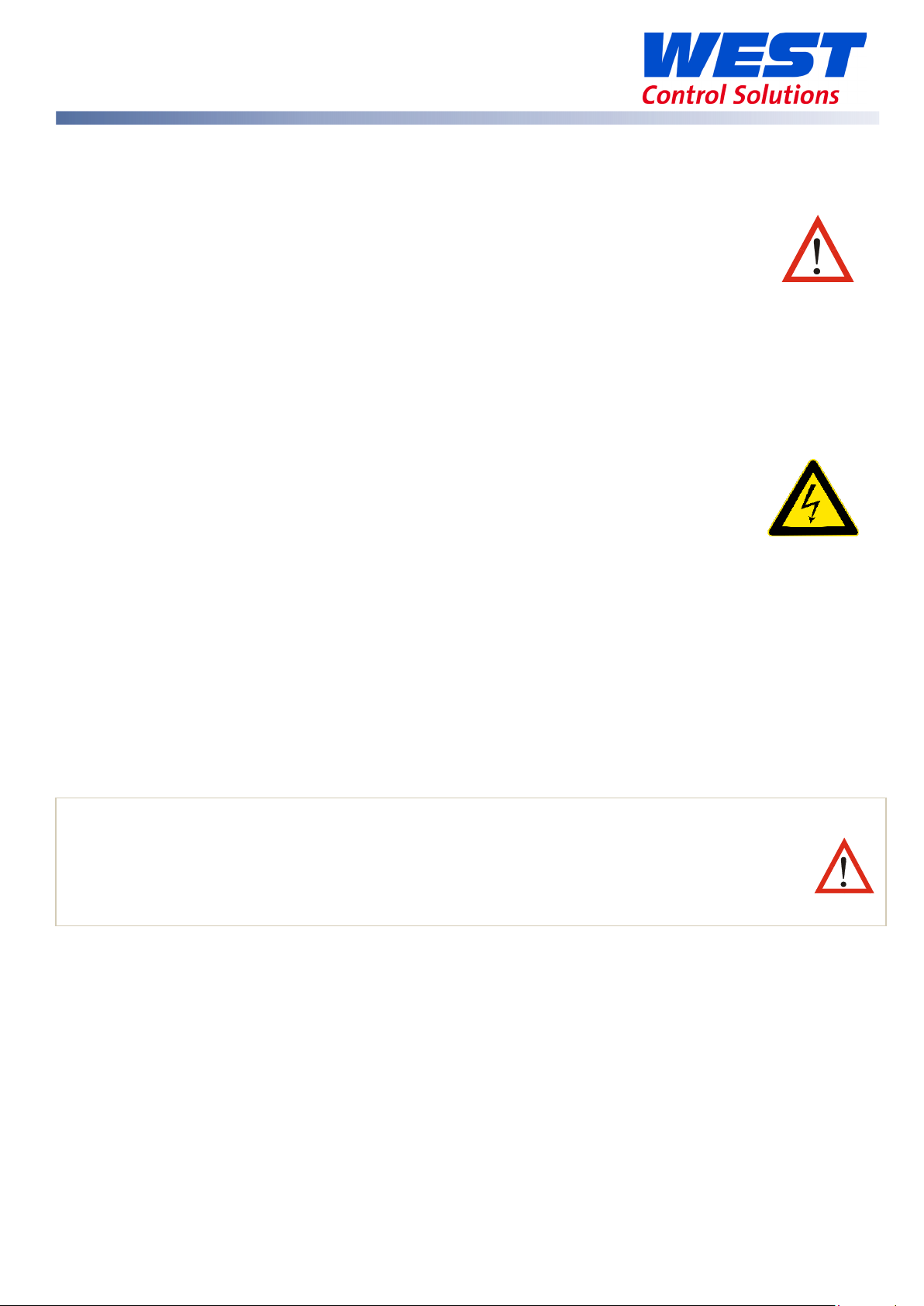
Noise Suppression at Source
Usually when good wiring practices are followed, no further noise protection is necessary.
Sometimes in severe electrical environments, the amount of noise is so great that it must be
suppressed at source. Many manufacturers of relays, contactors, etc. will supply 'surge suppressors'
which mount on the noise source. For those devices that do not have surge suppressors supplied,
Resistance-Capacitance (RC) networks and/or Metal Oxide Varistors (MOV) may be added.
Inductive coils
MOVs are recommended for transient suppression in inductive coils, connected in parallel and as
close as possible to the coil. Additional protection may be provided by adding an RC network
across the MOV.
Contacts
Arcing may occur across contacts when they open and close. This results in electrical noise as well
as damage to the contacts. Connecting a properly sized RC network can eliminate this arcing.
For any circuits of up to 3 Amps, a combination of a 47 Ohm resistor and 0.1 microfarad capacitor
(rated at 1000 Volts) is recommended. For circuits from 3 to 5 Amps, connect two of these in
parallel. Always observe the current rating of the relays on the controller and ensure this is not
exceeded.
59633-MaxVU Rail Full Manual (EN) - Page 14 of 127
Page 15
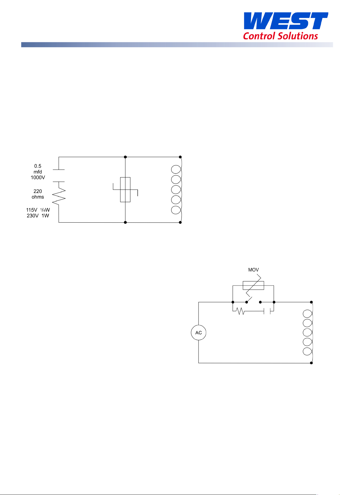
MaxVU Rail Product Labels
The example product & wiring label below is for illustration only. Actual label
information varies with the model code / hardware configuration purchased.
The product label shows the part number, production
information and approvals.
Model and Config codes make up the part number
(see MaxVU Rail Product Coding section), followed by
the unit serial number, country & date of manufacture,
and Product Revision Level.
The wiring label shows the power
requirements, connector positions
and terminal number.
This example is:
TOP
1 & 2 Rear = RS485 Comms
3 & 3 Rear = Linear Out 3
5 & 6 Front = SSR Driver Out 2
7 & 8 Front = 100-240VAC power.
BOTTOM
9 & 10 Rear = Digital Input
11, 12 Rear & 16 Front = Relay Out 1
13, 14 & 15 Front = Process Input
59633-MaxVU Rail Full Manual (EN) - Page 15 of 127
Page 16
Non-
Isolated
No Isolation
Reinforced Isolation
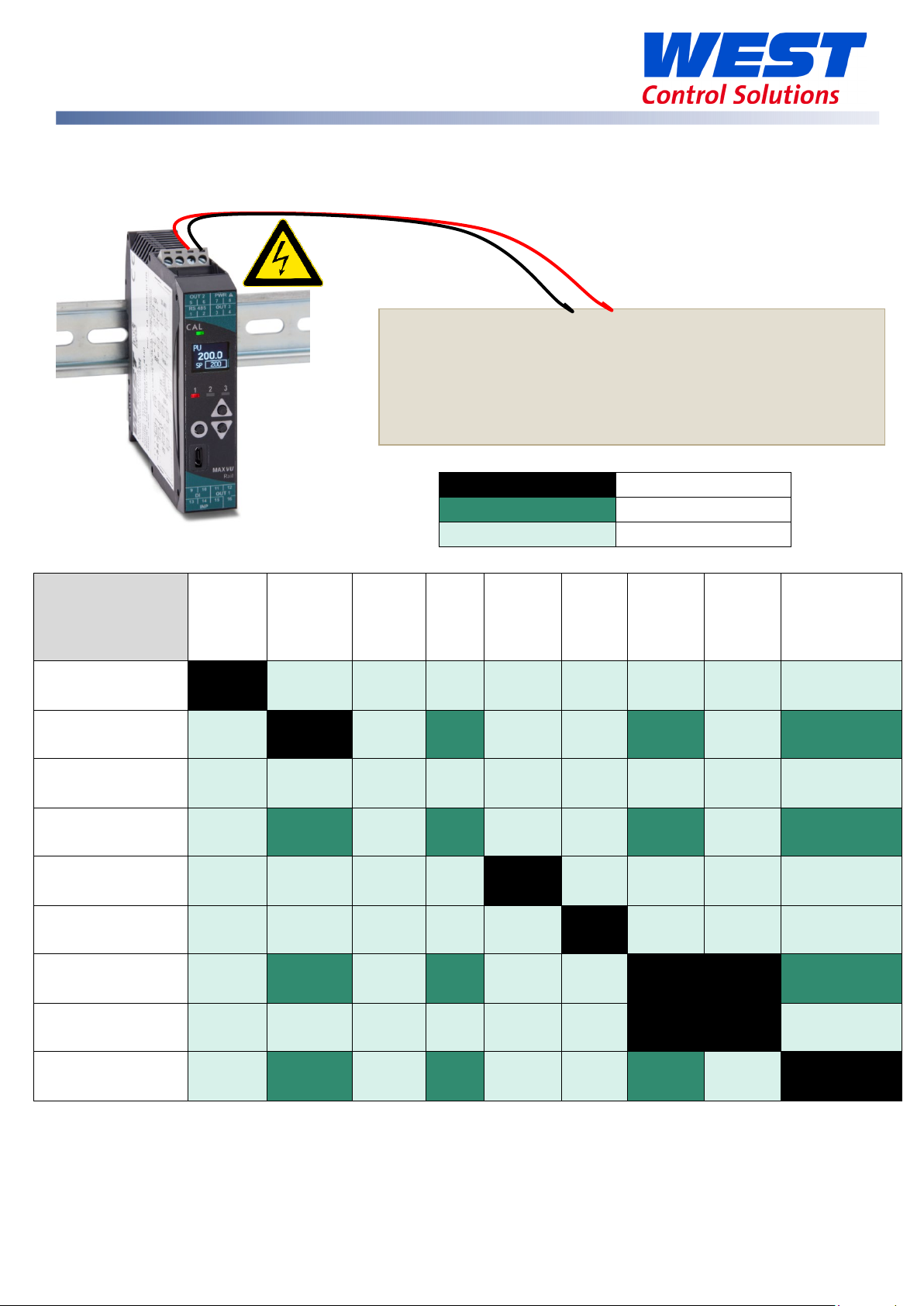
Power Connection
To avoid damaging your instrument it is critical the power connection is made to the correct
terminals.
Power is connected to pins 7 & 8.
Top, rear connector on the right-hand side.
(front connector omitted from picture for clarity)
The green LED shows when power is correctly connected.
Not Applicable
MaxVU Rail Isolation Chart
Universal
PSU
Universal Input
Relay
SSR
Linear
RS485 Comms
Non-Isolated
Digital Input
PSU
Input
Relay SSR Linear
RS485
Com
ms
Isolated
Digital
Input
Isolated
Digital
Input
Configuration
Port
Digital Input
Configuration Port
59633-MaxVU Rail Full Manual (EN) - Page 16 of 127
Page 17
Use cables with 80°C minimum temperature rating, conductor sizes 30-12 AWG.
1
RS485 A (Rx/Tx+)
2
RS485 B (Rx/Tx-)
L +
CONV-BA-00-00-00-MV.
1|2|3|4
Dedicated
5|6|7|8
13|14|15|16
9|10|11|12
Data A
Data B
Data A
Data B
Relay COM /
Relay NO /
+
Volt-free or TTL
compatible
Relay COM / SSR-
Relay NO / SSR+
TC / RTD / Linear +
TC / RTD / Linear -
RTD
Relay COM / SSR-
Relay NO / SSR+
Relay NC
Bus connector pin-outs
Diagrams show all possible option combinations so check
MaxVU Rail Terminal Wiring
Caution: Check information label on housing for correct operating voltage before
connecting supply to Power Inputs.
NEVER DIRECTLY CO
Configuration Port
configuration socket to a USB port, use adaptor
your exact product specification before connecting.
Never directly connect the dedicated
3
4
5
6
7
8
9
10
16
11
12
13
Communications
Linear +
Linear -
Output 3 – Standard & Extrusion
models
Output 2 – Standard & Extrusion
models
Power – low power or mains (hardware dependent)
Output 3 (Alarm 2 or Retx PV) – Limiter
model
Alarm 1 output – Limiter model
N -
Digital Input
Output 1 – Standard and Extrusion
models
Limit output – Limiter model (Relay only)
14
15
59633-MaxVU Rail Full Manual (EN) - Page 17 of 127
Input – thermocouple, RTD or linear
Page 18
Type
International
USA ANSI MC
British BS1843
French
German
+
Black
Black
White
Black
Yellow
Black
Yellow
Black
Red
Blue
-
White
Red
Blue
Black
Blue
+
Brown
Brown
Blue
Blue
White
Blue
Yellow
Blue
Red
Brown
-
White
Red
Blue
Blue
Brown
+
Green
Green
Yellow
Yellow
Brown
Red
Yellow
Yellow
Red
Green
-
White
Red Blue
Purple
Green
+
Pink
Pink
Orange
Orange
Orange
Orange
-
White
Red
Blue
+
Grey
Grey
Grey
Grey
Red
Grey
-
White
Red
Grey
+
Orange
Orange
Black
G
White
Green
Yellow
Green
Red
White
-
White
Red
Blue
Green
White
+
White
White
-
Red
+
-
Lead Colours
White
Red
Important: Using the wrong type of
Temperature Sensor Identification & Connection
Sensor Placement (Thermocouple or RTD)
If the temperature probe is to be subjected to corrosive or abrasive conditions, it must be
protected by an appropriate thermo-well. The probe must be positioned to reflect true process
temperature:
• In a liquid media - the most agitated area
• In air - the best circulated area
The placement of probes into pipe work some distance from the heating vessel leads to ‘transport
delay’, which results in poor control.
Locate the MaxVU as close as practical to the sensor to keep lead-length to a minimum.
Thermocouple
Thermocouples are identified by wire colour, and where possible, the outer insulation as well.
IEC584-3 is the most common standard, but several standards have been used worldwide. This
therefore is only a guide.
J
T
K
N
B
R & S
C (W5)
PT100
IEC584-3
*
*
Note:
* = Wire is magnetic
Red
96.1
Wire
Wire
reen
Sheath
NFC 42-324
DIN 43710
extension cable will cause incorrect
readings.
59633-MaxVU Rail Full Manual (EN) - Page 18 of 127
Page 19

Refer also to the Input Type range table in the Setup menu.
Thermocouple & RTD (PT100) Connections
Thermocouples
Connect your thermocouple to terminals 14 (positive) & 15 (negative). Carefully follow the chart
above, because correct polarity is vital for proper operation.
3 Wire RTD
The MaxVU Rail is designed to support a compensated 3 wire PT100. A PT100 normally 1 white and
2 red wires. The resistive element is between the white (connect to terminal 15) & 1 red wire
(connect to terminal 14). The 2nd red wire (connect to terminal 13) is required for automatic lead
length compensation.
2 Wire RTD
If is recommended to use a 3-wire PT100 RTD sensor. 2-wire PT100s should only be used with lead
lengths less than 3 metres. To use a 2-wire PT100 connect to terminals 14 & 15, then place a wire
link between terminals 13 & 14 in place of the third wire.
4 Wire RTD
A 4-wire PT100 can be used provided it is connected as a 3-wire type, with the 2
nd
white wire is not
used.
The resistive element is between the 1 white wire (connect to terminal 15) & 1 red wire (connect to
terminal 14). The 2
nd
red is connected to terminal 13 for the automatic lead length compensation.
The remaining white wire must be left unconnected (cut short or tied back to prevent it touching
other connections).
59633-MaxVU Rail Full Manual (EN) - Page 19 of 127
Page 20
3
COM
4
N/O
11
12
COM (Common)
N/O (Normally Open)
16
N/C (Normally Closed)
5 6 3
SSR drive -ve
4
SSR drive +ve
11
SSR drive -ve
16
SSR drive +ve
5 6 3
Linear +ve
4
Linear -ve
Relay Output Details
Relays are rated for 2A maximum at 250Vac (resistive load).
Output 1 (Relay option) Form A SPDT Output 2 or Output 3 (Relay option) Form C SPST
SSR Drive Output Details
The SSR driver outputs give a >10VDC ‘on’ signal at 20mA maximum. Use a separate connection
to the +ve & -ve of each output. Do not common together.
Output 1 (SSR Drive option) Output 2 or Output 3 (SSR Drive option)
Linear Output Details
The Linear Output is an option for Output 3. Select from 0 to 10V, 2 to 10V, 0 to 20mA, 4 to 20mA,
0 to 5V or 1 to 5V in the setup or input configuration menus.
Output 3 (Linear option)
59633-MaxVU Rail Full Manual (EN) - Page 20 of 127
Page 21
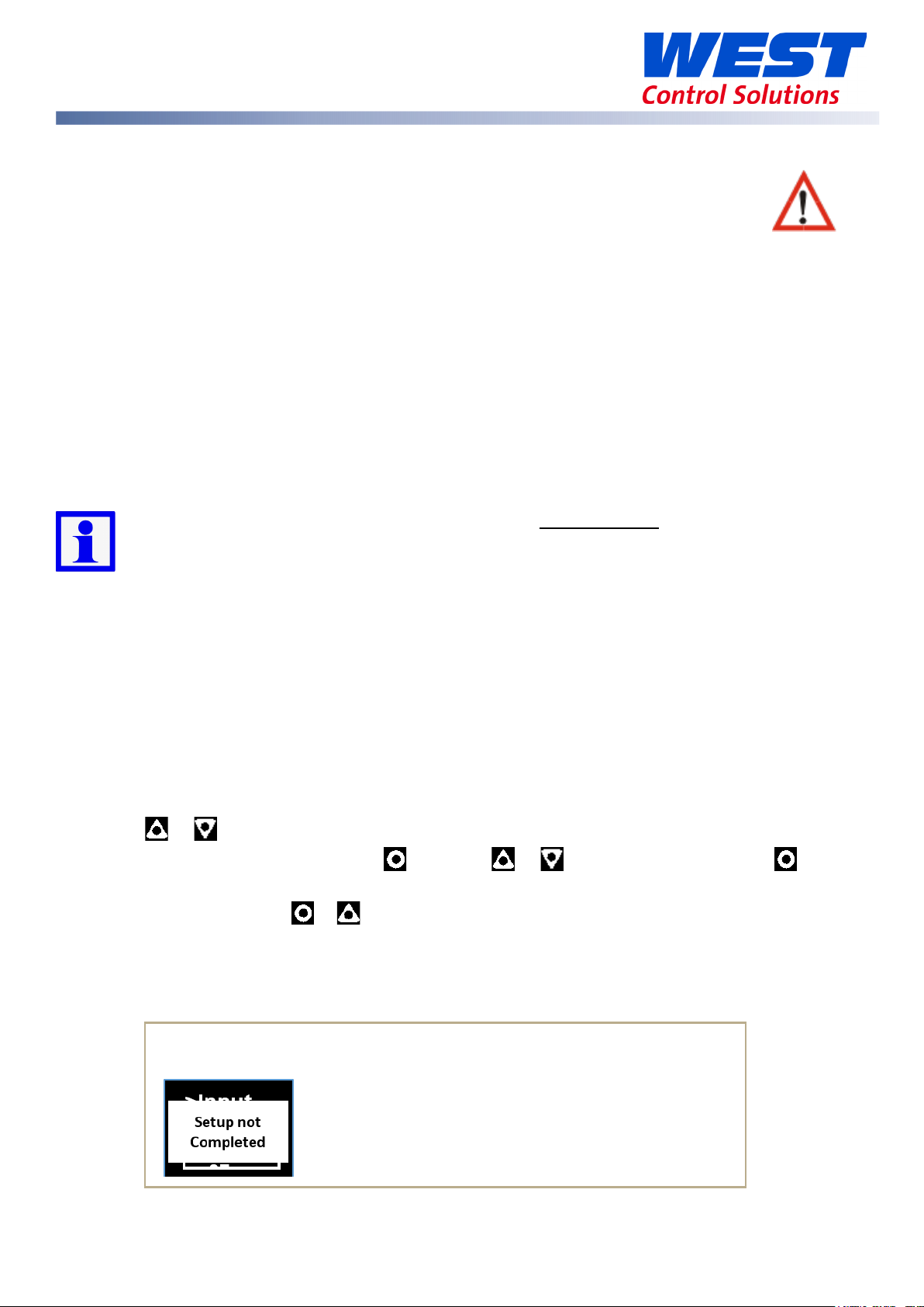
The Pop-Up alert “Setup not Complete” may appear as a reminder
Powering Up
ENSURE SAFE WIRING PRACTICES HAVE BEEN FOLLOWED.
WHEN POWERING UP FOR THE FIRST TIME, ISOLATE THE POWER FROM THE OUTPUT
CONNECTIONS.
The instrument must be powered from a supply according to the wiring label on the side of the
unit. (100vac to 240Vac, or 24 Vac/dc depending upon the model purchased.)
Carefully check the supply voltage and connections before applying power.
Powering Up Procedure
At power-up, a self-test procedure is run, during which a product logo screen is displayed.
When powering up for the first time the instrument starts up in the Setup Mode after the product
logo screen is displayed.
You must complete the Setup by cycling through all parameters before exiting the Setup
Mode, and using the device for the first time. Otherwise the device will go into the Setup
Mode, again, on subsequent power ups.
Once it has been correctly set-up, the instrument will enter the Operator Mode, after self-test,
and any future access to the Setup or Advanced Configuration Modes is lock code protected.
First Power Up or Factory Default
When the unit is initially powered up or the user restores the factory defaults to the device, it
immediately enters the Setup menu without requiring an unlock code. The user must then cycle
through every parameter, to either view or adjust the value, and then exit the menu.
1. Use or to review every parameter.
2. Change value if necessary using , then use or to adjust the value, then to
save.
3. Exit Setup by pressing & together.
If the above steps are not followed the Setup has not been completed so the device will go into
Setup, again, on every subsequent power up.
that you need to finish the Setup.
59633-MaxVU Rail Full Manual (EN) - Page 21 of 127
Page 22
Type
Purpose
Start-up Splash screen
Status LEDs
General temperature and other
PID or On/Off control.
1 2 3
Auto-Tuning from Setup menu
The controller can be auto-tuned from the Setup Mode.
1. Pre-tune
Pre-Tune auto-tuning will not engage if:
• Controller is set to On/Off control (Heat Proportional Band or Cool Proportional Band =
On.Off)
• Setpoint is ramping (Ramp Rate is not OFF)
• PV is within 5% of the input range (scale range) from Setpoint (applies for Pre-Tune only).
2. Auto-tune at setpoint
Auto-tune at setpoint auto-tuning will not engage if:
• Controller is set to On/Off control (Heat Proportional Band or Cool Proportional Band =
On.Off)
• Setpoint is ramping (Ramp Rate is not OFF)
• Start Tune at SP is not available for Heat & Cool processes.
Please also refer to the Automatic Tuning section for tuning advice.
MaxVU Rail Model Range
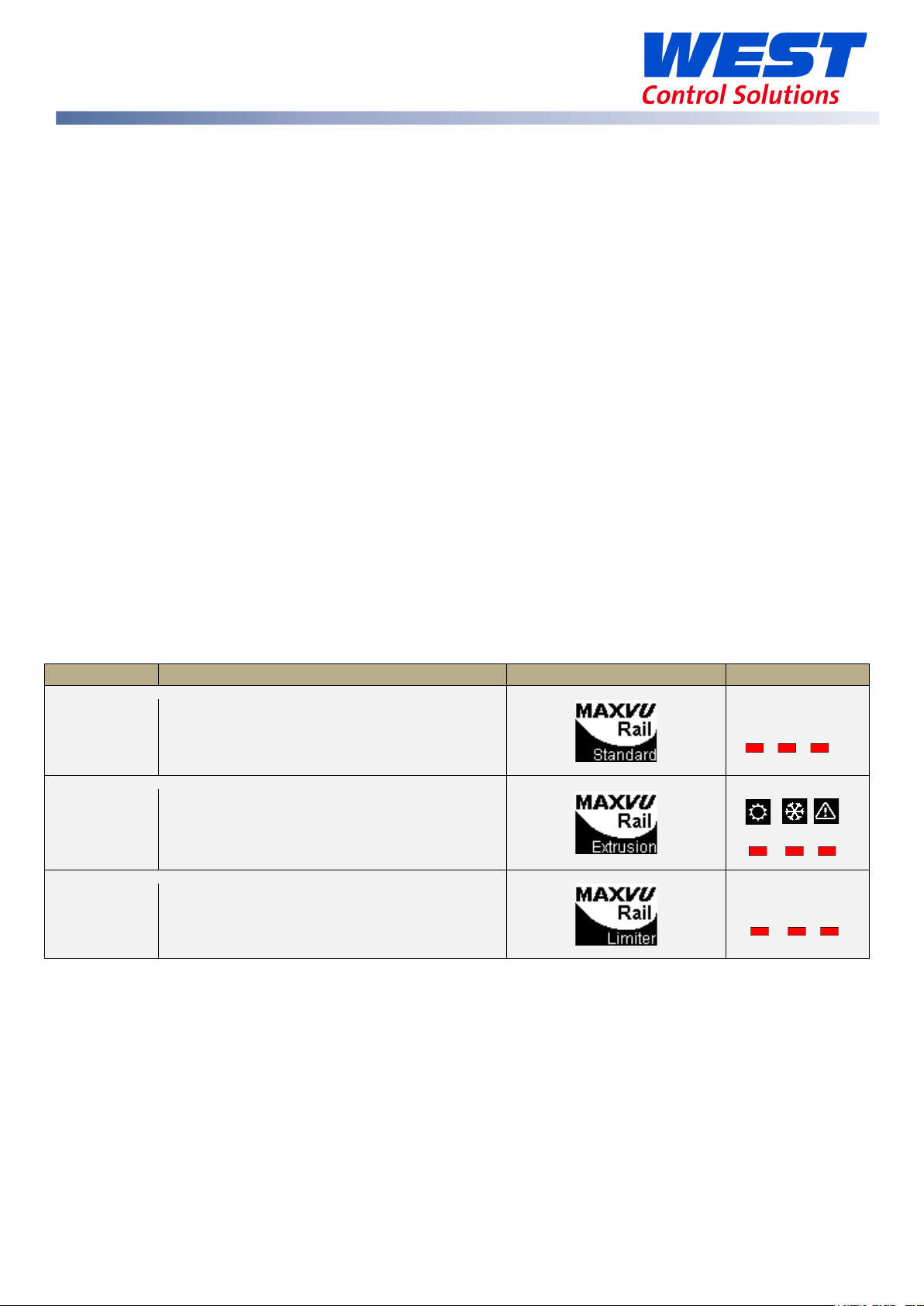
The MaxVU Rail has 3 different model types – Standard, Extrusion and Limiter. The table below
shows some easily recognisable differences and explains their intended purpose.
Standard
Extrusion
Limiter
Plastic extrusion applications –
Over or Under PV prevention, without
All models have mechanical characteristics, specifications and many of the parameters in
common. However, there is a separate section with more information focused on the Limiter.
The tables and parameters applicable to all models have grey or brown borders.
The parameters tables specific to the Standard and Extrusion models are blue, and the Limiter specific areas are green.
applications –
PID or On/Off control.
control functions.
LM EX AL
59633-MaxVU Rail Full Manual (EN) - Page 22 of 127
Page 23
3 navigation keys:
Standard:
Extrusion:
Limiter:
By default, the display turns off after 5 minutes without any key presses.
menu, parameter Screen Timeout. Any key press turns the display back on.
Front Panel
The main screen showing PV & SP, and the subsequent screens accessed from it using
or , are called the Operator Screens or Operator Mode.
Display shows PV (process variable), units, SP (setpoint), alarm/latch statuses,
error & warning messages.
This is configurable in the Advanced Configuration, in the Display sub-
Ok/Select
Up
Down
3 Output Status LEDs
1 2 3
3 Status LEDs for:
Heat Cool Alarm
3 Status LEDs for
LM EX AL
°C or °F are shown for temperature inputs only. Blank for linear type input (i.e. mA, V or
mV).
General Navigation & Editing
The device detects what options are fitted and intelligently hides parameters that are not relevant
to your current configuration.
These navigation instructions are common to all versions of the MaxVU Rail.
Press or keys to navigate between parameters or menu items.
Press to highlight a parameter value, ready for editing.
Press or to change the parameter value, then press within 60 seconds to confirm
change.
For example, changing the setpoint (SP). This example is for Standard or Extrusion models.
59633-MaxVU Rail Full Manual (EN) - Page 23 of 127
Page 24
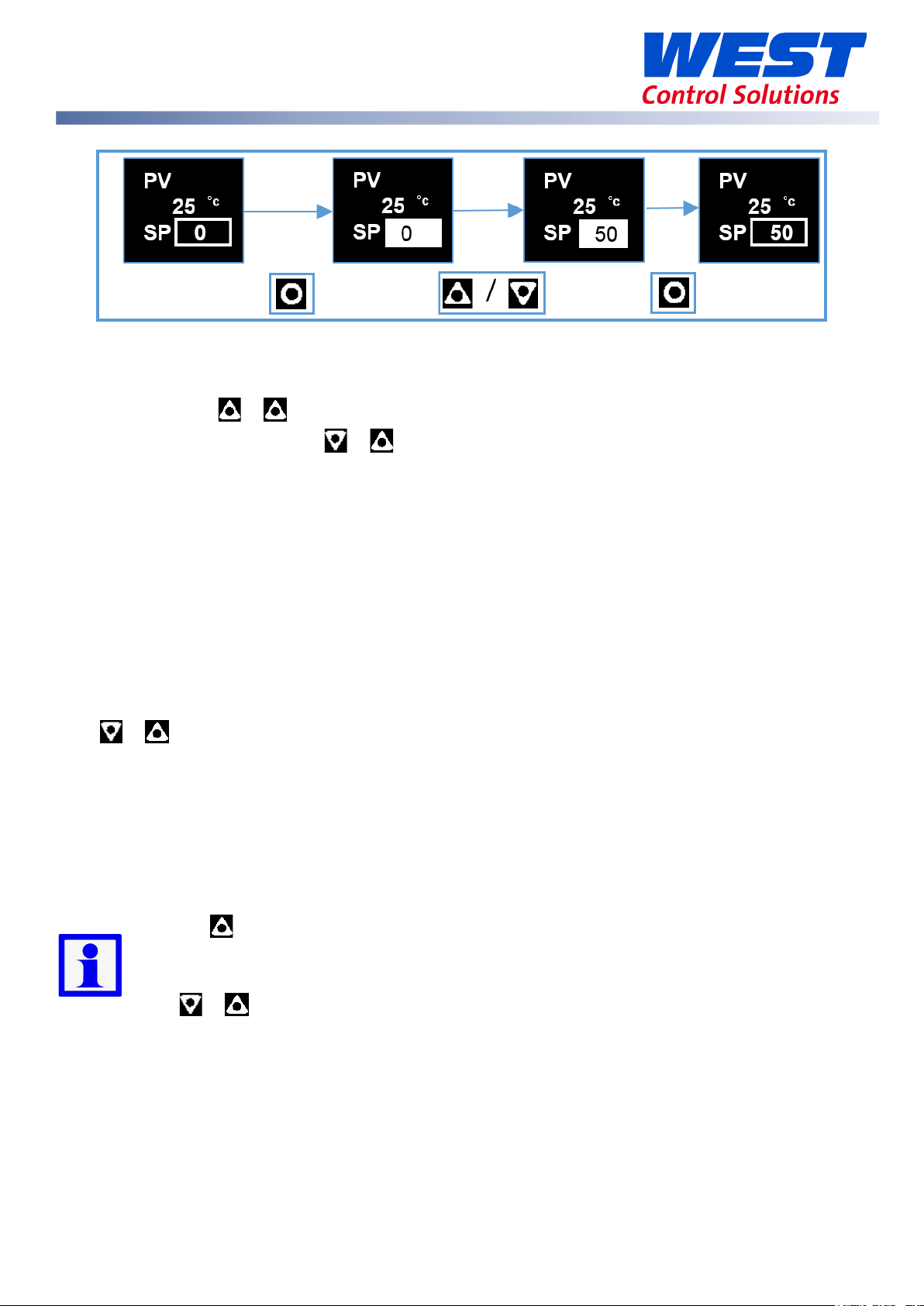
Navigating to Setup Mode or Advanced Configuration from Operator Mode
Setup Mode - press & .
Advanced Configuration - press & .
The Setup Mode has fewer parameters and is intended for quick set up of simple applications.
Advanced Configuration gives access to all parameters for more complex application.
Mode Access and Lock Codes
Separate lock codes can be set for the Setup mode and for the Advanced Configuration mode.
Setup mode lock code – default
Advanced Configuration mode lock code – default
10.
20.
Returning to Operator Mode
Press & to move back one level (from Advanced Configuration sub-menus you may need
to move up 2 or more levels). After 120 seconds without key presses the unit returns automatically
to the first Operator mode screen.
Lock Code View Screen
If you don’t know the lock codes for any of the password protected menus, they can be found as
follows:
Hold the button whilst powering up for the lock code view screen and from this
screen the lock-codes (passwords) can be seen or changed. Be patient, it takes approx.
30 seconds to enter this screen at start-up.
Press & to exit.
59633-MaxVU Rail Full Manual (EN) - Page 24 of 127
Page 25

minutes:seconds
hours:minutes
Time Display
Time values are displayed on the MaxVU Rail as shown in the examples below.
Use of the Controller for Non-Temperature Applications
In this controller, the Primary and Secondary outputs are referred to as “HEAT” and “COOL”.
The majority of applications for the Standard model controller involve temperature measurement
and control, either via a direct sensor or indirectly via a linear dc input. However, this model can
also be used for other process types, such as Relative Humidity, for example.
If your process is not temperature, then the parameters labelled as “HEAT” refer to reverse acting
outputs used to increase the process value and “COOL” to decrease the process value.
As an example, you may have a system that reads and controls humidity. The “HEAT” output
drives the humidifier (adding moisture) and the “COOL” output drives the de-humidifier
(extracting the moisture from the air). Use the “HEAT” parameters to control the humidifier and the
“COOL” parameters to control the de-humidifier.
MaxVU Rail use as a Transmitter
The Standard MaxVU Rail model can be used as a “transmitter” to retransmit the process value or
controller setpoint via Output 3, if the linear option is fitted. The parameter Usage in the Linear
Output sub-menu can be set to PV Retransmit or SP Retransmit.
In the Display menu, the parameter Transmitter can be used to enable Transmitter view. This hides
the Setpoint from view. Note: control functions will remain active if they have been configured.
59633-MaxVU Rail Full Manual (EN) - Page 25 of 127
Page 26
Transmitter screen is present on Standard model only.
Transmitter parameter = Enable, SP is hidden.
in
PV
Show”
Operator
Alarm State
Alarm State
Alarm 1
Alarm 2
Loop
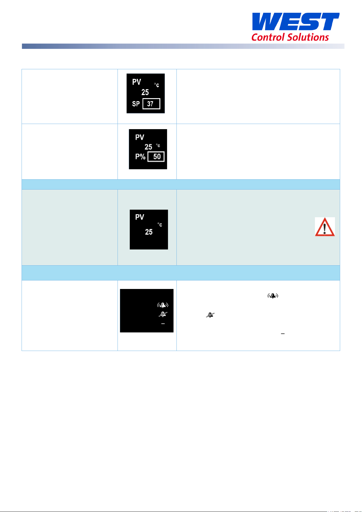
Operator Mode & Screens on Standard & Extrusion models
User Screen
Temperature Unit.
PV – process variable (e.g. process temperature)
SP - Setpoint
Manual control
PV – process variable (e.g. process temperature)
Manual Power is shown as P%.
Important: The device still functions as a controller
Transmitter view enabled
using the local Setpoint.
To act as a PV transmitter the parameter Usage
the Linear Output sub-menu needs to be set to
Retransmit.
Important: The following parameters are only displayed if set to “
Alarm configured, but not triggered
in the
sub-menu.
Alarm triggered
Alarm not set
59633-MaxVU Rail Full Manual (EN) - Page 26 of 127
Page 27
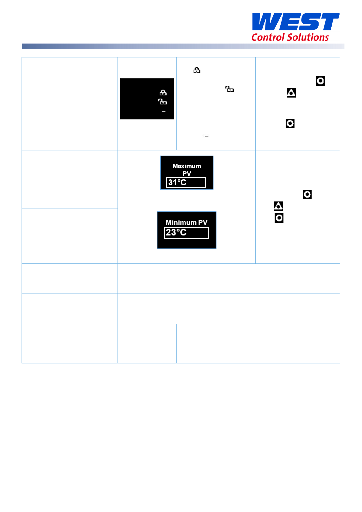
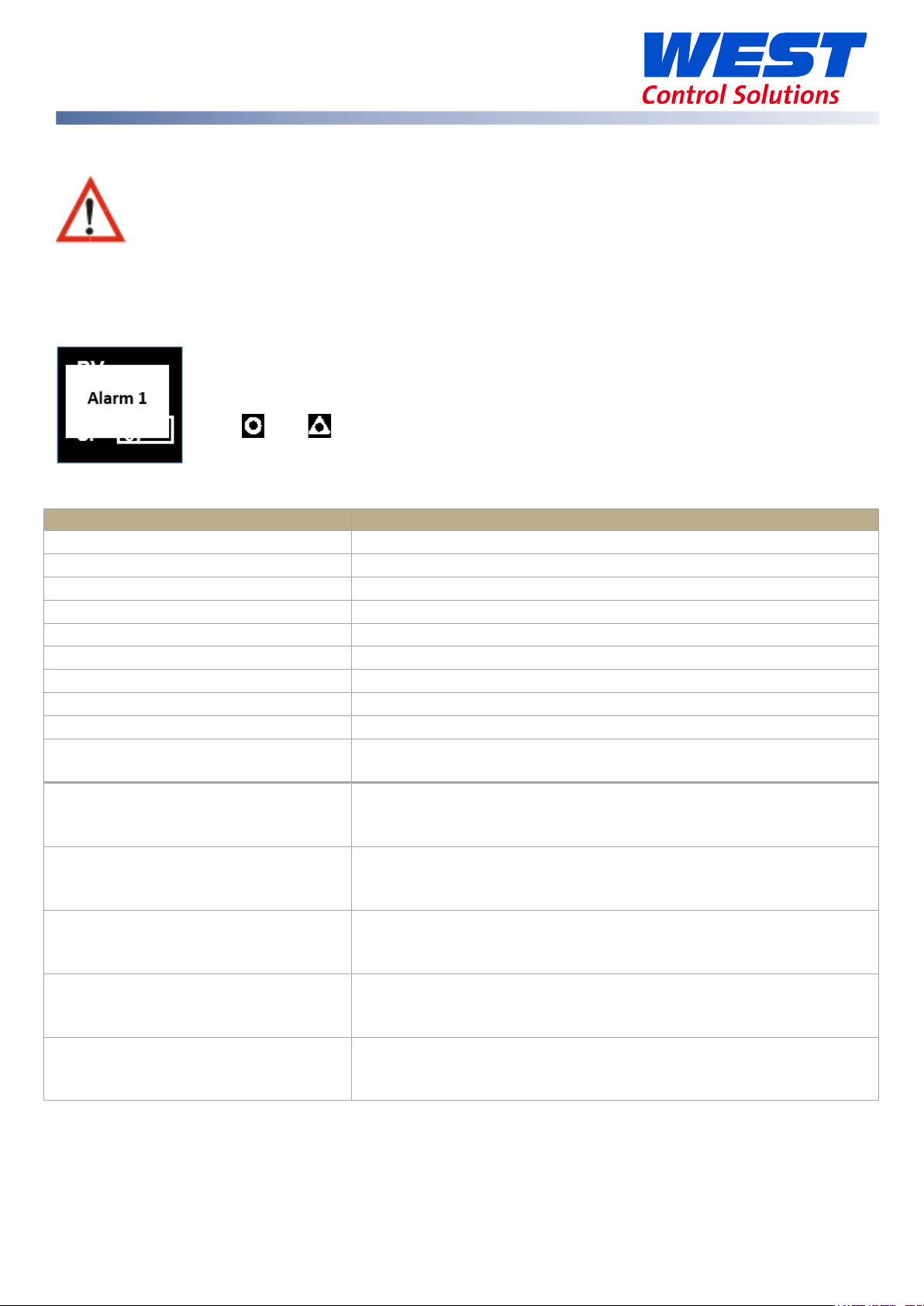
Latch State
Output Latched
Latch
, but
output not
Maximum PV
Minimum PV
Control Enable
OFF
ON
Manual Control Enable
OFF
ON
P% xxx
Time On Remaining
Visible when On Timer is active.
Delay Time Remaining
Visible when Delay Timer is active.
Latch State
Out 1
Out 2
Out 3
configured
Latched
Latch not set
Screens show the Maximum & Minimum
PV reached.
To clear press
then to select
Yes.
Press to accept.
To clear press
then to select “Yes”.
Press to accept.
59633-MaxVU Rail Full Manual (EN) - Page 27 of 127
- Control output(s) disabled. (Ignored when in manual mode).
- Control output(s) enabled.
- Automatic control, PID or On-Off control available.
- Manual control, Manual Power shown as
On Timer
Delay Timer
See Ramp & Timers diagram.
See Ramp & Timers diagram.
.
Page 28
Message
Description
Alarm 1
Alarm 1 is active.
Alarm 2
Alarm 2 is active.
Alarm 1 & 2
Alarm 1 and 2 are active.
Control Enabled
Alerts user that the control is re-enabled. (not Limiter.)
Calibration Pass
Factory calibration (Full Input Calibration has passed.)
Calibration Fail
Factory calibration (Full Input Calibration has failed.)
Tuning in Progress
Tune at Setpoint or Pre-Tune is running. (Not Limiter.)
Setup not completed
Please refer to First Power Up or Factory Default section.
Offset in use
SP offset is being used in Setpoint sub-menu.
Limiter only, indicates when the limit value has been
exceeded.
Warnings & Messages
Do not continue running your process until any issues are resolved.
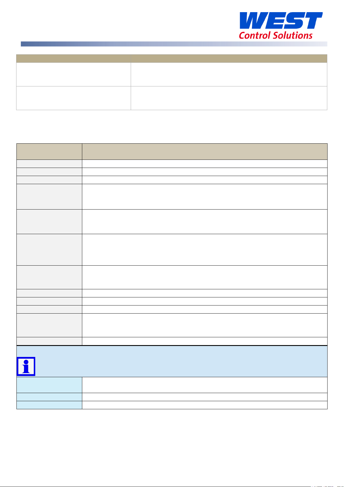
Pop-Up Alerts
Pop-up alerts appear in front of the current screen. They must be acknowledged before you can
access other screens.
For example, Pop-up alert for Alarm 1.
Press and together to clear the pop-up alert.
Pop-Up Alert List
Limit Exceeded
Tune Error
PV within 5% of SP
Tune Error
Setpoint is ramping
Tune Error
Control is ON/OFF
Tune Error
Control is manual
Tune Error
Tune at Setpoint not able to run
PV within 5% of the scale range input from SP (for Pre-Tune).
Try a different setpoint or narrow the scale range input.
Setpoint is ramping. Turn off ramping and try again.
Control is not set to PID, i.e. the proportional band = 0. Set the
proportional band to any other value and try again.
Manual control enabled when attempting Pre-Tune. Use Tune
At Setpoint or set Manual Control Enable to OFF.
Tune at setpoint has timed out or cannot run.
59633-MaxVU Rail Full Manual (EN) - Page 28 of 127
Page 29
Message
Description
ALARM
Alternates with PV and shows one, or both, Alarms are active.
LATCH
Alternates with PV, one or more outputs are latched on & no alarm is active.
LIMIT
On Limiter model, alternates with PV to show Limit is active.
Process variable input >5% over-range.
Process variable input >5% under-range.
Also, check that Scale Range Minimum is low enough for your application.
Break detected in process variable input sensor, wiring or wrong input type
OPEN
models), or Limit state set until resolved on Limiter model.
Selected input range is not calibrated.
models), or Limit state set until resolved on Limiter model.
TUNE
Alternating with SP shows Auto-tuning is in progress.
P%
Manual power value replaces setpoint, shows P% xxx of power.
Ramp
Setpoint ramp is active (alternates with actual setpoint).
Control is disabled. Control output(s) are off.
Input if Digital I/P Action is set to Ctrl Enable/Disable.
DELAY
Shows when Delay Timer is active, control is off until the timer finishes.
Tuning messages
tErr1
PV within 5% of the scale range input from SP (for Pre-Tune). Try a different
setpoint or narrow the scale range input.
tErr2
Setpoint is ramping.
tErr3
Control is ON/OFF. Control is not set to PID, i.e. the proportional band = 0.
Tune Error
Sensor Break
Tune Error
Timer Running
Message List
Messages seen in the operator mode.
Message Description
Check your sensor.
Timer Running. Set the Enable Timer parameter to Disabled.
HIGH
Check for possible issues with sensor or connections.
Also, check that Scale Range Maximum is high enough for your application.
LOW
OPEN
ERROR
OFF
Check for possible issues with sensor or connections.
selected.
Shows
until resolved, Control is disabled on Standard or Extrusion
Shows ERROR until resolved, Control is disabled on Standard or Extrusion
Enable control by setting Control Enable to ON or check state of the Digital
The Automatic Tuning parameter must be changed to Off to clear any tuning message.
Display alternates between the tuning code & setpoint.
59633-MaxVU Rail Full Manual (EN) - Page 29 of 127
Page 30

tErr4
Control is manual. Set Manual Control Enable to OFF.
tErr5
Tune at Setpoint not able to run.
tErr6
Sensor Break.
tErr7
Timer Running. Set the Enable Timer parameter to Disabled before attempting
to run tuning again.
tErr8
Control is disabled. Please check it is safe to enable control and then go to
the User menu to change Control Enable to ON.
Tuning messages
The Automatic Tuning parameter must be changed to Off to clear any tuning message.
Display alternates between the tuning code & setpoint.
59633-MaxVU Rail Full Manual (EN) - Page 30 of 127
Page 31

A confirmation screen appears.
MaxVU Rail Factory Defaults
The factory default values for parameters are shown in the right-hand column of the parameter
lists. When the factory default process is performed all the parameters will be returned to these
values.
The Reset to Defaults can be found in the sub-menu Display in the Advanced Configuration
on all models.
Factory Default procedure
Press to highlight No.
Press to move highlight to Yes.
Press to accept.
If you are sure press to show Yes (leave as
No to cancel).
Press to confirm your choice.
The instrument shows the default for the Input
Type and its default value.
The user must review all parameters in the
Setup menu before exiting.
59633-MaxVU Rail Full Manual (EN) - Page 31 of 127
Page 32

Parameter
Description
Default Value
* Maximum of 1 decimal place for temperature inputs J, K, L, T & PT100.
J Thermocouple *
-200 – 1200ºC
-128.8 – 537.7ºC
K Thermocouple *
-240 – 1373ºC
-128.8 – 537.7ºC
PT100 *
-199 – 800ºC
-128.8 – 537.7ºC
B Thermocouple
100 – 1824ºC 211 – 3315ºF
C Thermocouple
0 – 2320ºC 32 – 4208ºF
L Thermocouple *
0 – 762ºC
0.0 – 537.7ºC
N Thermocouple
0 – 1399ºC 32 – 2551ºF
R Thermocouple
0 – 1795ºC 32 – 3198ºF
S Thermocouple
0 – 1762ºC 32 – 3204ºF
T Thermocouple *
-240 – 400ºC
-128.8 – 400.0ºC
Setup mode parameters for Standard & Extrusion models
If necessary, press & to enter Setup from Operator mode.
Enter code for Setup Lock (default = 10) using & , then press .
1. For the Limiter model refer to the Limiter Model focus section.
2. Some parameters may be hidden depending on the model or other settings.
3. Note the permissible ranges for each temperature sensor type, below. For example,
the B type thermocouple readings cannot have a decimal point, and it cannot
measure below 100 ºC or above 1824 ºC
4. Where allowed the number of decimal points is set by the Decimal Place parameter.
The table below continues onto the next page.
>Input
Type
-328 – 2192ºF
-400 – 2503ºF
-328 – 1472ºF
32 – 1403ºF
-199.9 – 999.9ºF
-199.9 – 999.9ºF
-199.9 – 999.9ºF
K Thermocouple
32.0 – 999.9ºF
-400 – 752ºF
59633-MaxVU Rail Full Manual (EN) - Page 32 of 127
-199.9 – 752.0ºF
Page 33

Parameter
Description
Default Value
Linear dc
0 – 20mA
4 – 20mA
** 0 – 50mV is only linear dc input available on Extrusion models.
>Input
Units parameter hidden when linear input is used and units are not shown on the display
0000 – no decimal point
Scale Range maximum & minimum are only visible when input is a linear dc type.
>Input
Maximum for user working range.
>Input
Minimum for user working range.
None
Heat
>Output 2
Same options as Output 1 Usage
>Output 3
Same options as Output 1 Usage
If a Relay or SSR drive is fitted in Output 3 you will see >Output 3.
If the Linear option is fitted in Output 3 you will see the >Linear Outp menus instead.
Units
>Input
Decimal Place
Scale Range Maximum
Scale Range Minimum
>Input
Digital I/P Action
0 – 50mV**
0 – 5V
0 – 10V
10 – 50mV
1 – 5V
2 – 10V
°C or °F
000.0 – one decimal point
00.00 – two decimal points (linear dc only)
0.000 – three decimal points (linear dc only)
Alarm Reset (clears latched alarms)
Ctrl Enable/Disable (disables control)
Ctrl Auto/Manual
Pre-Tune Start/Stop
Tune at SP Start/Stop
°C
0000
1000
0
None
Cool
Non Linear Cooling (on Extrusion model only)
>Output 1
Usage
Alarm 1
Alarm 2
Alm. 1or 2 (logical ‘OR’ of Alarm 1 & 2)
Loop Alarm
Usage
Usage
59633-MaxVU Rail Full Manual (EN) - Page 33 of 127
Heat
Alarm 1
Alarm 2
Page 34

Parameter
Description
Default Value
Heat
0-10V
Maximum PV or SP value corresponding to
Minimum PV or SP value corresponding to
Range minimum to range maximum,
OFF
Same options as Alarm 1.
Setpoint
Target setpoint.
0
>Coms Unit Address
Modbus address from 1 to 255
1
>Coms Baud Rate
1200, 2400, 4800, 9600, 19200 & 38400 bps
9600
>Coms Parity
Odd, Even or None
None
>Control
>Linear Outp
Usage
>Linear Outp
Type
>Linear Outp
Scale Range Maximum
>Linear Outp
Scale Range Minimum
>Alarm 1
Value
>Alarm 2
Value
Cool
PV Retx
SP Retx
2-10V
0-20mA
4-20mA
0-5V
1-5V
maximum linear output for retransmission.
minimum linear output for retransmission.
or OFF (maximum +1).
disables alarm.
Default PV High alarm type.
Default PV Low alarm type.
PV Retx
0-10V
1373
-240
1373
-240
Automatic Tuning
Off, Start Pre-Tune or Start Tune at SP *** Off
1. *** The Start Tune at SP function is not available for Heat & Cool processes.
2. If the Input Type is changed, input scaling and alarm values are set to new values
based on the maximum and minimum of the new input type. If necessary, review these
settings.
If necessary, press and to clear the “Control is Enabled” Pop Up Alert then
press & to exit the Setup mode.
59633-MaxVU Rail Full Manual (EN) - Page 34 of 127
Page 35

Menu Name (letters are sub-menus)
1. User
7. Alarms
2. Input
8. Communication
3. User Calibration
9. Display
4. Outputs
10. Operator Screens
5. Control
11. Information
6. Setpoint & Timer
Advanced Configuration mode for Standard & Extrusion models
The Advanced Configuration mode gives access to all the parameters accessible from the front
panel; however, the device hides parameters that are not relevant to your exact model code
specification & configuration.
The Advanced Configuration mode has eleven menus, some of which contain further sub-menus.
a) Alarm 1
b) Alarm 2
c) Options
a) Output 1
b) Output 2
c) Output 3 or Linear Outp
Please refer to the Limiter Model for those models.
The Setpoint can be locked by setting Setpoint Upper Limit and Setpoint Lower Limit to the
same value.
For basic applications, it may be sufficient to use the simpler Setup mode to set-up. See previous
sections.
Otherwise, press & to enter Advanced Configuration from Operator screen.
Enter Advanced Lock-code (default of 20) using and , then press .
59633-MaxVU Rail Full Manual (EN) - Page 35 of 127
Page 36

Parameter
Description
Default Value
Alarm triggered
Output Latched
Screens show
OFF
ON
OFF
ON
P% xxx
Alarm State
Alarm 1
Alarm 2
Loop
Latch State
Out 1
Out 2
Out 3
User menu
Applicable to both Standard & Extrusion models.
Alarm State
Latch State
Alarm set, but not
triggered
n/a
Alarm not set
Latch configured,
but output not
n/a
Latched
Latch not set
To clear any latched outputs, press then to select Yes.
Press to accept.
Maximum PV
To clear the stored value press then to select
Yes.
Minimum PV
Press to accept.
- Control output(s) disabled. (Ignored when in
Control Enable
manual mode).
- Control output(s) enabled.
- Automatic control, PID or On-Off control
Manual Control Enable
available.
- Manual control, Manual Power shown as
the Maximum
& Minimum PV
reached.
ON
OFF
59633-MaxVU Rail Full Manual (EN) - Page 36 of 127
Page 37

Parameter
Description
Default Value
Refer to Input types in the table in the Setup
Display Units either °C or °F.
Units hidden when linear input is used and no unit is shown on the display
0000
For temperature inputs, enter the maximum
For temperature inputs, enter the minimum
Input filter time value to reduce noise.
Enable Enables the internal thermocouple CJC
None
Input menu
Applicable to Standard & Extrusion models.
Input Type
Units
Decimal Place
Scale Range Maximum
Scale Range Minimum
Filter Time
menu section for a full list of inputs available.
This parameter is hidden when input is a linear
type and °C or °F are hidden from the display.
000.0
00.00 (not for temperature)
0.000 (not for temperature)
working range. For linear inputs, enter the
display value for the maximum input level
working range. For linear inputs, enter the
display value for the minimum input level.
OFF or 0.5 to 100.0 seconds in 0.5 increments
K thermocouple
°C
0000
Maximum allowed
for Input Type.
Minimum allowed
for Input Type.
2.0
CJC Enable
(Cold Junction Compensation).
Disable Disables the internal CJC. If disabled,
external compensation must be provided.
Alarm Reset (clears latched alarms)
Digital I/P Action
Ctrl Enable/Disable (disables control)
Ctrl Auto/Manual
Pre-Tune Start/Stop
Tune at SP Start/Stop
The input scale range, consisting of Scale Range Maximum & Scale Range Minimum
above, is used to narrow the working range of the controller.
If the measured value is more than 5% above or below the scaled range PV display is
replaced by HIGH (over-range) or LOW (under-range).
The scale range also affects if Pre-Tune will run. If the PV is <5% of the scaled range from
setpoint Pre-Tune cannot be used.
Enable
None
59633-MaxVU Rail Full Manual (EN) - Page 37 of 127
Page 38

Parameter
Description
Default Value
Shifts the input value up or down by this offset
Enter value at which the low point error was
Enter equal, but opposite offset value to the
Enter value at which the high point error was
Enter an equal, but opposite offset value to the
Parameter
Description
Default Value
Output 1 sub-menu
Direct
Reverse
Off
On
Direct
Reverse
User Calibration menu
Applicable to Standard & Extrusion models.
Offset
Low Point
Low Offset
High Point
High Offset
value, across the entire range.
measured.
observed low point error.
measured.
observed high point error.
Outputs menu
Applicable to Standard & Extrusion models.
Heat (Reverse acting control)
Cool (Direct acting control)
Non Linear Cooling (Extrusion model only)
Usage
(i.e. logical ‘OR’ of Alarm 1 & 2)
Alarm 1
Alarm 2
Alm. 1or2
Loop Alarm
0
Lower Limit
0
Upper Limit
0
Heat
- Output active when alarm triggers
Alarm Action
- Output active when alarm is not
triggered
- Alarm doesn’t latch
Latching
– Alarm latches (remains in active state until
cleared)
LED Indicator
59633-MaxVU Rail Full Manual (EN) - Page 38 of 127
- LED Indicator lit when output is active
- LED Indicator lit when output is inactive
Direct
Off
Direct
Page 39

Parameter
Description
Default Value
Output 2 sub-menu
Usage
Same options as Output 1 - Usage
Alarm 1
Alarm Action
Same options as Output 1 - Alarm Action
Direct
Latching
Same options as Output 1 - Alarm Latching
Off
LED Indicator
Same options as Output 1 - LED Indicator
Direct
Output 3 sub-menu
If a Relay or SSR drive is fitted in Output 3, this sub-menu is visible.
Usage
Same options as Output 1 Usage
Alarm 2
Alarm Action
Same options as Output 1 - Alarm Action
Direct
Alarm Latching
Same options as Output 1 - Alarm Latching
Off
LED Indicator
Same options as Output 1 - LED Indicator
Direct
Linear Outp sub-menu
If the Linear option is fitted in Output 3, this sub-menu is visible.
Heat (Reverse acting control)
0-10V
Display value at which retransmission output is at
Display value at which retransmission output is at
Usage
Type
Scale Range Maximum
Scale Range Minimum
Cool (Direct acting control)
Retransmission of PV or SP:
PV Retx
SP Retx
2-10V
0-20mA
4-20mA
0-5V
1-5V
its maximum value ( -1999 to 9999)
its minimum value ( -1999 to 9999)
PV Retx
0-10V
1000
0
59633-MaxVU Rail Full Manual (EN) - Page 39 of 127
Page 40

Parameter
Description
Default Value
The Proportional Bands for heating and cooling
control
control
value
Visible when On/Off control & Loop Alarm
assigned to an
Sets time before the loop alarm triggers.
(minutes & seconds)
Manual Reset. Biasing of the control working
Heat Cycle Time
0.1 to 512.0 seconds
32.0
Cool Cycle Time
32.0
Prevents simultaneous activation of both heat &
Heat Power Limit
% heating and cooling power upper limits
100%
Cool Power Limit
100%
Last - Powers up with control enable/disable in
Control menu for Standard model only
Proportion Heat Band
, in display units. Set to ON/OFF (0) or PID
161
. Display resolution defines possible
s/resolution:
1 to 9999 - 0 decimal places
0.1 to 999.9 - 1 decimal place
Proportion Cool Band 161
0.01 to 99.99 - 2 decimal places
0.001 to 9.999 - 3 decimal places
Auto Reset (Integral)
Overlap/
Deadband
Differential
(On/Off)
Loop Alarm Time
0.01 to 99.59.
and OFF (0.00) (minutes & seconds).
In display units, range -20 to +20% of Heat &
Cool Proportional Band
Visible when using On-Off control.
In display units centred about the setpoint.
Range: 0.1% to 10.0% of input span
output.
5.00
0
8
99.59
Manual Rst (Bias)
point, 0 to 100%. (-100% to 100% if heat/cool
control)
Relay/SSR control output cycle times
Output Interlock
cool outputs. Choose from On or Off.
Do not use if PB ‘overlap’ has been set
0 to 100%
Power Up Action
the same state as on power off or power failure.
On - Always powers up with control enabled.
Off - Always powers up with control disabled.
59633-MaxVU Rail Full Manual (EN) - Page 40 of 127
25%
Off
Last
Page 41

Parameter
Description
Default Value
Off
Parameter
Description
Default Value
The Proportional Bands for heating and cooling
control
control:
Possible
display resolution.
Visible when using On-Off control.
Visible with On-Off control & Loop Alarm
assigned to an
Sets time before the loop alarm triggers.
(minutes & seconds)
Soft Start Time
0:01 to 60:00 or OFF (0:00) (hours & minutes)
OFF
The setpoint used by the Soft Start.
Heat Cycle Time
0.1 to 512.0 seconds
32.0
Cool Cycle Time
32.0
Automatic Tuning
Start Pre-Tune
Start Tune at SP (Not available for Heat & Cool
Off
processes.)
Control menu for Extrusion model only
, in display units. Set to ON/OFF (0) or PID
Proportion Heat Band
1 to 9999 - 0 decimal places
0.1 to 999.9 - 1 decimal place
0.01 to 99.99 - 2 decimal places
Proportion Cool Band 161
0.001 to 9.999 - 3 decimal places
values/resolution depends on values
Auto Reset (Integral)
0.01 to 99.59. (minutes & seconds)
and OFF (0.00).
161
5.00
Overlap/
Deadband
Differential
(On/Off)
In display units, range -20 to +20% of Heat &
Cool Proportional Band. -ve values=Deadband.
In display units centred about the setpoint.
Range: 0.1% to 10.0% of input span
Loop Alarm Time
Manual Rst (Bias)
Soft Start Setpoint
Manual Reset. Biasing of the control working
point, 0 to 100%.
(-100% to 100% if heat/cool control)
See Soft Start function section.
Relay/SSR control output cycle times
output.
0
8
99.59
25%
-240
59633-MaxVU Rail Full Manual (EN) - Page 41 of 127
Page 42

Parameter
Description
Default Value
Prevents simultaneous activation of both heat &
Heat Power Limit
% heating and cooling power upper limits,
100%
Cool Power Limit
100%
Non-linear cooling pulse time.
Minimum non-linear cooling pulse time.
Attenuates effective cooling vs PID cooling
Off
Output Interlock
Minimum Cooling
Impulse Length
Minimum Off Time
Non Linear Adjust
Power Up Action
Automatic Tuning
cool outputs. Choose from On or Off.
Do not use if PB ‘overlap’ has been set
adjustable from 0 to 100%
Sets the minimum temperature at which water
cooling will activate.
0.01 to 99.99 (seconds)
0.01 to 99.99 (seconds)
power. From 1 to 999.9
Last - Powers up with control enable/disable in
the same state as at power off.
On - Always powers up with control enabled.
Start Pre-Tune
Start Tune at SP (Not available for dual Heat &
Cool)
Off
120
10
20
5
Last
Off
59633-MaxVU Rail Full Manual (EN) - Page 42 of 127
Page 43

Parameter
Description
Default Value
Enabled
OFF
Rate the actual setpoint changes from current PV to target
The time the target setpoint will be maintained once
Used to limit Minimum setpoint value.
Scale Range
For use in multi-zone setpoint slave applications.
Setpoint menu for Standard model only
Refer to Delay, Ramp and Timer diagram.
- Enables the Delay and On Timers. Applies at next
Enable Timer
Delayed Start Time
power-up or next control enable.
Disabled - Delay and On Timers are ignored.
(Setpoint ramping still functions.)
Time from power-up or control enable before control begins
from 00.01 to 99.59 (hours & minutes) or OFF (0.00).
If delay is OFF control starts immediately.
Disabled
Ramp Rate
setpoint following power-up or control enable.
From 0.001 to 9999 (Units / hr) or OFF (10000).
Any changes in the setpoint value also follow this rate.
On Time
reached, from 00.01 to 99.59 (hours & minutes) or Off (00.00)
Set to >99.59 for Infinite - control remains on indefinitely.
Upper Limit Used to limit the Maximum setpoint value.
Lower Limit
Offsets the setpoint from -1999 to 9999. Effective SP =
Offset
SP+Offset. NOTE: effective SP is not limited by setpoint limits.
‘Offset in use’ pop-up appears when SP is changed.
OFF
Infinite
Scale Range
Maximum
Minimum
0
59633-MaxVU Rail Full Manual (EN) - Page 43 of 127
Page 44

Parameter
Description
Default Value
Rate the actual setpoint changes from current PV to target
Us
Scale Range
For use in multi-zone setpoint slave applications.
Parameter
Description
Default Value
Alarm 1 sub-menu
Value
Value for the alarm, from Range minimum to
1373
Hysteresis
Sets the alarm switching differential from 1
1
Alarm 2 sub-menu
PV Low
Value
-240
Hysteresis
1
Setpoint menu for Extrusion model only
Ramp Rate
setpoint following power-up or control enable.
From 0.001 to 9999 (Units / hr) or OFF (10000).
Any changes in the setpoint value also follow this rate.
Upper Limit Used to limit the Maximum setpoint value.
Lower Limit
ed to limit Minimum setpoint value.
Offsets the setpoint from -1999 to 9999. Effective SP =
Offset
SP+Offset. NOTE: effective SP is not limited by setpoint limits.
‘Offset in use’ pop-up appears when SP is changed.
Alarm menu
Applicable to Standard & Extrusion models.
None
PV High
Type
PV Low
Deviation
Band
OFF
Scale Range
Maximum
Minimum
0
PV High
range maximum, or OFF (maximum +1).
OFF disables the alarm.
display unit to the full input span.
Type
Same options as Alarm 1 sub-menu.
59633-MaxVU Rail Full Manual (EN) - Page 44 of 127
Page 45

Parameter
Description
Default Value
Options sub-menu
Inhibiting of ‘active alarms’ at power-on, control
Alternates ‘Alarm’ with PV value if selected
Sensor Break Alarm
On - activates both alarms, if configured, when
Parameter
Description
Default Value
Unit Address
Modbus address from 1 to 255
1
Coms data rate in kbps
Parity
Parity checking: Odd, Even or None
None
Parameter
Description
Default Value
View & adjust Setup lock code.
Advanced Unlock
View & adjust Advanced lock code.
Screensaver time. Display turns off after 5, 15 or 30 mins.
Alarm Inhibit
Alarm Notification
enable or controller setpoint change.
None
Alarm 1
Alarm 2
Alarm 1 & 2 (both alarms are inhibited)
alarm(s) are active. Red alarm output LEDs are
not affected by this parameter.
None
Alarm 1
Alarm 2
Alm. 1and2 (Alarm 1 OR 2)
None
Alm. 1and2
a sensor break is detected. If Off, alarms
activate only break condition is an alarm
condition.
Communications menu
Applicable to Standard & Extrusion models.
Baud Rate
1200, 2400, 4800, 9600, 19200 & 38400 bps.
Display menu
Applicable to Standard & Extrusion models.
Setup Unlock Code
From 1 to 9999 or Off for no lock code.
Off
9600
10
Code
From 1 to 9999 or Off for no lock code.
Screen Timeout
59633-MaxVU Rail Full Manual (EN) - Page 45 of 127
20
5
Page 46

Parameter
Description
Default Value
Choose the display language (English plus one other). From:
‘Enable’ hides the setpoint, SP.
Used to reset all parameters back to the factory defaults, as shown on the
right in parameter lists.
See
Parameter
Description
Default Value
Selected language
English & German
English & French
The second language offered can be changed via the
configuration software.
English
Transmitter
Important: The device still functions as a controller
Disable
even though the SP is hidden.
Reset to Defaults
the Default Value column in the Setup and Advanced menu tables.
Operator Screens menu
Applicable to Standard & Extrusion models.
Control Enabled
Manual Ctrl Enabled Hide
Alarm State Hide
Latch State Show
Hide or Show parameters in Operator Mode.
For security, or to simplify the operator screens,
Maximum PV Hide
hide any that you do not need to allow access to.
Hide
Minimum PV Hide
Remaining On Time
(Standard model only)
Remaining Delay Time
(Standard model only)
59633-MaxVU Rail Full Manual (EN) - Page 46 of 127
Hide
Hide
Page 47

Parameter
Description
PRL
The hardware/software revision level, used for internal quality control.
FW Version
Serial
Display of the Serial Number.
Shows the outputs types fitted. These cannot be changed after
Shows other options fitted. These cannot be changed after
Information menu
Applicable to Standard & Extrusion models, read-only menu.
DOM
The Date of manufacture in mmyy format
Display of the units’ firmware version & code type numbers.
FW Type
Out1
Out2
Out3
Comm
DI
manufacture. Options are: –
SSR (SSR driver) or Relay
SSR (SSR driver) or Relay
None, SSR (SSR driver), Relay or Linear
manufacture. Options are: –
RS485 communications - Fitted or None.
Digital Input is isolated or not - Iso or NonIs
Exiting the Advanced Configuration mode
If necessary, press and to clear any Pop-Up Alerts.
Press & to move up one menu level. Some menus have sub-menus so it may be necessary
to press this key combination more than once to exit.
59633-MaxVU Rail Full Manual (EN) - Page 47 of 127
Page 48

This example shows a positive offset value.
For example:
If the process displays 27.8 when it should read
30, The error is
would change the displayed value to 30.
The same offse
100.0 the new displayed value would be 102.2
and at 0.0 the new displayed value would be
2.2.
Single Point ‘Offset
Calibration’ value
New Displayed
Original Displayed Value
User Calibration Menu
It is possible to calibrate the controller to compensate for sensor errors etc.
The user calibration menu allows single and 2-point calibration offsets to be applied. The method
used will be dependent on the process application. Use two-point calibration to change the
calibration slope angle and/or single point to offset all readings by a fixed amount (raising or
lowering the calibration slope).
Note: These methods do not alter the internal instrument calibration. Set the offset values
back to zero to restore standard measured values. Re-calibration of the internal base
calibration is also possible, but should only be attempted by qualified personnel as it
overwrites the factory calibration – see Base Input Calibration below.
Single point calibration (PV Offset)
This is a ‘zero offset’ applied to the process variable across the entire span. Positive values are
added to the reading; negative values are subtracted.
This can be used if the error is constant across the range, or the user is only interested in a single
critical value.
To use, select Single Point Calibration from the input calibration menu, and simply enter a value
equal, but opposite to the observed error to correct the reading.
59633-MaxVU Rail Full Manual (EN) - Page 48 of 127
-2.2 so an applied offset of +2.2
t is applied to all values, so at
Page 49

This example shows a positive Low Offset and
New Displayed Value
Calibration High
Calibration Low Offset
Calibration High
Process Value
Calibration
Low Process
Original Displayed Value
Two Point Calibration
This method is used where an error is not constant across the range to change the calibration
slop. Separate offsets are applied at two points in the range to eliminate both “zero” and “span”
errors.
1. Measure and record the error at a low point in the process.
2. Measure and record the error at a high point in the process.
3. Go to the first two-point input calibration screen.
a. Enter the desired low point value as the Calibration Low PV value.
b. Enter an equal, but opposite value to the observed error as the Calibration Low Offset to
correct the error at the low point.
4. Go to the second two-point input calibration screen.
a. Enter the desired high point as the Calibration High PV value.
b. Enter an equal, but opposite value to the observed error as the Calibration High Offset to
correct the error at the high point.
Important: Choose values as near as possible to the bottom and top of your
usable span to achieve maximum calibration accuracy. The effect of any error
can grow at values beyond the chosen calibration points.
The single and two-point calibration methods can be used together, if you need to change the
calibration slope and offset the zero point simultaneously.
a negative High Offset.
For example:
If the process displays a low-end error where
+0.5 displays as 0.0, an offset of +0.5 corrects
the value to +0.5.
A high-end value of 100.0 with a -1.7 offset
would read 98.3.
There is a linear relationship between these
two calibration points.
59633-MaxVU Rail Full Manual (EN) - Page 49 of 127
Page 50

Base Input Calibration
Calibration of the input is carried out during manufacture, and for most applications, recalibration is not required during the lifetime of the instrument. User 1-point and 2-point calibration
can be carried from the User Calibration menu.
Re-calibration of the internal base values is possible, but should only be attempted by qualified
personnel as it overwrites the factory calibration.
Equipment Required for Checking or Calibrating the Universal Input
A suitable calibration signal source is required for each input type. To verify the accuracy of the
instrument or carry out re-calibration, the input sources listed below are required, with better than
±0.05% of the reading accuracy:
1. DC linear inputs: 0 to 50mV dc, 0 to 10V dc & 0 to 20mA dc.
2. Thermocouple inputs - complete with 0ºC reference facility, appropriate thermocouple
functions and compensating leads (or equivalent).
3. RTD inputs: decade resistance box with connections for three-wire input (or equivalent).
Calibration Check
1. Set up the instrument to the required input type.
2. Note down, then remove any single or two-point calibration values by setting them to zero.
3. Power up the instrument and connect the correct input leads, to the correct terminals.
4. Leave powered up for at least five minutes for RTD and DC linear inputs, or at least 30
minutes for thermocouple inputs.
5. After the appropriate delay for stabilisation has elapsed, check the calibration by
connecting the appropriate input source and checking a small number of cardinal points.
6. Repeat the test for all required input types.
7. Check the results against the specification stated for the required input type.
8. Reinstate the calibration values removed at step if they are still appropriate.
Make the connections using the correct thermocouple cable type. For all other input
types use copper cable. Using the wrong type of cable will cause incorrect readings.
This is especially important with thermocouple sensors.
59633-MaxVU Rail Full Manual (EN) - Page 50 of 127
Page 51

>mV Input
Base Calibration Procedure
Input calibration is carried out in five phases as shown below, each phase corresponds to an input
range of the instrument.
Caution:
The 50mV phase must be calibrated first before any other range(s).
Calibration phases:
i. mV for 50 mV
V for 10 V
ii.
iii.
mA for 20 mA
RTD input (200 Ω ohm resistance source)
iv.
CJC (K type thermocouple source at 0ºC required)
v.
For Extrusion models phase ii and iii (V & mA) are omitted.
Make the thermocouple connection using the K type thermocouple cable for the CJC
calibration phase. For all other phases use copper cable. Using the wrong type of
cables will cause incorrect calibration.
Calibrating the mV Input
1. Check your calibration source is connected to the correct terminals on the MaxVU Rail. For
50mV, connect your mV source +ve to pin 14 and -ve to pin 15 located on the bottom rear
connector – see wiring section.
2. Press and hold the button, whilst the instrument is powering up, until the display shows
the screen starting with mV. Be patient, may take approximately 30 seconds.
3. In the calibration phase menu displayed, highlight mV from the list
4. With mV selected, press . The following screen will appear:
userCAL
Press enter
to start
59633-MaxVU Rail Full Manual (EN) - Page 51 of 127
Page 52

5. Press . You should see the messages Starting Calibration, followed by Calibration in
Progress. A dot moves across the display to show the progress.
6. If the input is wrongly connected or an incorrect signal is applied the calibration will be
aborted and the display will show Calibration FAIL. The previous calibration value will be
retained.
7. If the calibration was successful, the display shows Calibration PASS.
8. To clear the Pass or Fail pop-up press and .
9. Now press and to return to the calibration menu. From here either select another
calibration phase, or press and again to return to the operator screen
.
Calibrating other input types
The 50mV calibration must be carried out first. After this, you can select the
other types in turn. The other calibration phase procedures are similar to the mV
phase above, but ensure that the correct input signal and connections are
used – see the wiring section for connection details.
Note: When calibrating the RTD input type, connect an accurate 200Ω resistance source across
pin 14 and pin 15, and link between pin 13 and pin 14 to replicate the 3-wire compensating lead.
When you have completed the required phases, press and to exit back to the operator
screen.
The Calibration Mode automatically exits if there is no button activity for five minutes.
59633-MaxVU Rail Full Manual (EN) - Page 52 of 127
Page 53

Description
State Shown
Description
Popup
Starting calibration
.
Calibration in progress
.
Description
Comment
Dec
Hex
50mV Calibration
1700
6A4
10V Calibration
1701
6A5
20mA Calibration
1702
6A6
RTD Calibration
1703
6A7
CJC Calibration
1704
6A8
Calibration Input States
Each input can have one of three states:
Input not calibrated noCAL
Factory calibrated factCAL
User calibrated userCAL
Calibration Progress
Initial popup
During calibration
Calibration succeeded Calibration PASS
Calibration failed Calibration FAIL
Calibration Modbus Addresses
The following Modbus addresses can be used to initiate the calibration phases and read back the
status.
Calibration Status
Write 0xCAFE to start the calibration
for the selected input.
0x0000 - Calibration Failed
0xCAFE - Calibration Busy
0xFFFF - Calibration Successful
Write
Only
Read
Only
1770 6EA
59633-MaxVU Rail Full Manual (EN) - Page 53 of 127
Page 54

Automatic Tuning
To avoid process time-lags that can make effective tuning difficult or even impossible, ensure
correct sensor and heat source positioning in your application before use.
There are two automatic tuning methods on the MaxVU Rail. Pre-Tune and Tune at SP.
The Pre-Tune is a ‘start-up disturbance’ tuning method. It usually gives better results than Tune at
SP. However, a minimum 5% of span distance between the process value and setpoint is required
for Pre-Tune to run. This means it cannot be used if the setpoint is close to ambient temperature. In
this case, use Tune at SP. A full description of Pre-tune and Tune at SP is in the Glossary.
Refer to the Warnings & Messages section for information on the Tuning Error messages.
Running the Pre-Tune
1. For best results, before running the Pre-Tune adjust the input span (Scale Range Maximum
and Scale Range Minimum) to suit your process, allowing a small tolerance beyond the
operating range. e.g. if operating from ambient to 180°C, perhaps set the range 0 to 200.
2. Run from cool. Ideally the process should to be cool before running Pre-Tune. Disable
control, or temporarily lower the setpoint, until the PV is a least 5% of the input span
difference between the current SP and PV. A larger gap is better if this is possible.
3. Allow for overshoot and undershoot. Please be aware that when the Pre-Tune is run, full
power is applied to the process for some time. Although the controller cuts power before
the setpoint is reached, some process over/undershoot should be expected. The overshoot
might exceed the setpoint value. If exceeding SP might cause a problem, run your first PreTune with a lower SP. If required and safe to do so, you can run another Pre-Tune closer to
the required SP.
4. The Pre-Tune can be activated via the Automatic Tuning parameter in the Setup menu or
the Advanced Configuration menu. It may also be activated via a Modbus command.
The message ‘TUNE’ is displayed whilst Pre-Tune is running.
Pre-Tune will not engage, and a Tune Error message will be displayed under the following
conditions: 1). There is a sensor break, 2). The PV is <5% of span from SP, 3). A setpoint ramp
has been set, 4). A Timer is running, 5). The current control mode is On-OFF 6). The controller
is in Manual mode. 7). Control is Disabled*. Resolve the displayed problem then run Tune at
SP again if required. *Note: If control is disabled, running Pre-Tune at First Power-up (or
immediately after a Reset to Default) automatically sets the control to enabled.
5. Once Pre-Tune is complete it will disengage, and the ‘TUNE’ notification ends. The length of
time the tuning takes to complete will vary from process to process.
59633-MaxVU Rail Full Manual (EN) - Page 54 of 127
Page 55

Running Tune at SP
1. Initial PID values. Tune at SP needs a reasonable level of process stability to run. It is
therefore recommended to set the initial PID values in the Control menu back to their
default values: Proportional Band to 10% of your chosen input range, Auto Reset (Integral)
to 5.00 and Rate (Derivative) to 1.15 before using Tune at SP.
2. The Tune at SP can be activated via the Automatic Tuning parameter in the Setup menu or
the Advanced Configuration menu. It may also be activated via a Modbus command.
The message ‘TUNE’ is displayed whilst Tune at SP is running.
3. Once Tune at SP is complete it will disengage, and the ‘TUNE’ notification ends. The length
of time the tuning takes to complete will vary from process to process
Tuning at SP Troubleshooting
Tune at SP will not engage, and a Tune Error message will be displayed under the following
conditions: 1). There is a sensor break, 2). A setpoint ramp has been set, 3). A Timer is running, 4).
Control is Disabled. 5). The current control mode is On-OFF.
Resolve the displayed problem then run Tune at SP again if required.
If Tune at SP starts, but remains running indefinitely, the cause is either the process value not
achieving reasonable stability (±1% of span), or the control power variation is too great (±10%)in
Automatic control mode. To resolve this:
Switch to Manual mode and set the manual power level to a value that brings the process to
the approximate setpoint value you need, but do take care not to allow the process to reach
unacceptable levels.
When the process is approximately stable at the required value, re-activate Tune at SP.
When Tune at Setpoint has completed, return the controller to Automatic control mode.
Alternatively, if manual mode is not available, do the following from automatic mode:
Check the PID values in the control menu were at the defaults values (see above). If they were
correct, go to step 2. Otherwise, correct them and run Tune at SP again.
1. If step 1 has not resolved the issue, observe the displayed process value for >5minutes and
noting the highest and lowest values seen. Subtract the lowest value from the highest to
find the peak-to-peak deviation. Check the input span (Scale Range Maximum minus the
Scale Range Minimum) to see if the it is >100 x the peak-to-peak deviation. If not, increase
the input span to more than this value, and run Tune at SP again.
2. If this has not resolved the issue, double the current PID terms (Proportional Band, Auto Reset
and Rate values), then run Tune at SP again.
3. In the unlikely event that the tuning still does not complete continue from step 3.
59633-MaxVU Rail Full Manual (EN) - Page 55 of 127
Page 56

Controller
Digital Input State Transition
Functions
High to Low
Low to High
Reset Latched Alarm(s)
No Action
Reset*
Control Enable/Disable
Disable
Enable
Auto/Manual
Manual
Automatic
Pre-Tune Start/Stop
Stop
Start*
Tune at SP Start/Stop
Stop
Start*
Limiter
Digital Input State Transition
Function
High to Low
Low to High
Reset Latched Limit & Alarm(s)
No Action
Reset*
Tuning at SP for Heat and Cool
Tuning at SP is possible for Heating or Cooling applications, but not for both Heat and Cool
together. If you have defined outputs for heating and cooling, Tune at SP is not offered in the
tuning menu. Instead use Pre-Tune.
Digital Input Operation
Depending on your model, the digital input can be used to perform one of the available functions
as shown in the table below.
High = Open contacts (and 2 to 24Vdc for the isolated digital input).
Low = Closed contacts (and <0.8Vdc for the isolated digital input).
*Alarm outputs only reset if the alarm condition is no-longer present and tuning will only start if the
settings and current process conditions allow (see tuning section for more details)
*Limit and Alarm outputs only reset if the limit exceed and/or alarm conditions are no-longer
present.
When the instrument is turned on, a change in the digital input signal from High Low, or Low to
High will cause the function to change (unless it is already in the state dictated by the signal
change).
The keypad can also be used to change the status of the same function via the relevant menu.
The most recent digital input or keypad instruction will be implemented.
Note: The digital input is “edge sensitive”, which means that it only reacts to a detected
transition in the input state. The device cannot detect a status change made when it is turned off.
It also means that if it is in the “ON” state, but the current condition of the unit is the “OFF” state
59633-MaxVU Rail Full Manual (EN) - Page 56 of 127
Page 57

(either because a keypad instruction or it has powered up that way) the digital input would first
have to be set first to OFF and then ON again before it would set the function ON.
However, on the Limiter model if the Digital Input is in an “ON” state at power-up it gives a Reset
signal. Once powered up the Limiter model behaves the same way to a transition.
59633-MaxVU Rail Full Manual (EN) - Page 57 of 127
Page 58

CONTROL FUNCTION
Control Enabled
Control Disabled
DIGITAL INPUT
Signal High
Signal Low
HMI
Menu says “ON”
Menu says “OFF”
Control Function
Control Enabled
Control Disabled
Digital Input
Signal High
Signal Low
HMI
Menu
Menu
Below is an illustration of digital input and keypad use. The example is for the Control Enable
function. Other functions behave in a similar way.
Unit
Start-up
– “ON”
– “OFF”
1. On start-up, the unit uses the Power-Up Action for its initial control state. In this example, it
starts in the disabled condition.
2. Digital input signal changes from Low to High; therefore, control becomes enabled. The
Control Enable parameter will say ON, when viewed from the HMI (front panel).
3. The keypad on the HMI (front panel) menu is used to change the control back to disabled,
Control Enable parameter = OFF.
4. The digital input changes state, going from High to Low, but as the control is already
disabled no change is made.
5. Then the digital input goes from Low to High again, re-enabling the control. The Control
Enable parameter in the HMI also shows control is ON again.
59633-MaxVU Rail Full Manual (EN) - Page 58 of 127
Page 59

Control state
Power-up
Timer Enable
Delayed
Control state at power-up
Enabled
Last
Disabled
N/A
Control Enabled
Disabled
Last
Disabled
N/A
Control Disabled
Enabled
On
Disabled
N/A
Control Enabled
Disabled
On
Disabled
N/A
Control Enabled
Enabled
Last
Enabled
Off
Control Enabled
Disabled
Last
Enabled
Off
Control Disabled
Enabled
On
Enabled
Off
Control Enabled
Disabled
On
Enabled
Off
Control Enabled
Enabled
Last
Enabled
Time Set
Control Disabled until Delay timer expires
Disabled
Last
Enabled
Time Set
Control Disabled
Enabled
On
Enabled
Time Set
Control Disabled until Delay timer expires
Disabled
On
Enabled
Time Set
Control Disabled until Delay timer expires
Timer Feature
The timer feature is only available on the Standard model. It consists of a Delay Timer and an On
Timer.
When the Timer Enable parameter is set to Disabled the timer will not be used and the delayed
start time and on time are ignored. Note: If the setpoint has been set to ramp, this will still be
active, even if the timer is Disabled.
When Enabled the timer will take control of the Setpoint as defined by the Delayed Start Time and
On Time parameters. Enabling the timer has no effect until the controller is power cycled or the
control is disabled then re-enabled.
The timer, control power down state and the power-up action have the following relationship:
at power
down
Action
setting
parameter
setting
Start Value
59633-MaxVU Rail Full Manual (EN) - Page 59 of 127
Page 60

①
②
③
④
Delay, Ramp and Timer diagram
The delay, ramp and soak is only available on the standard model.
① From power-up, if control is in the enabled state, or whenever control is changed from
disabled to enabled, the unit delays process control (i.e. control is still disabled) until the Delay
Timer expires (time as set by Delayed Start Time). If this is OFF, step 1 is omitted.
② Setpoint ramps from the current PV to the target setpoint at Ramp Rate (‘RAMP’ alternating
with the current effective SP value indicates it is still ramping). If Ramp Rate is OFF the effective
setpoint steps directly to target setpoint.
③ After any Delay and/or Ramp completes, the setpoint ‘Dwells’ at the target value while the
On-Timer counts down (time set by On Time).
④ When the On Timer finishes the control switches off (i.e. control is disabled). If the On Timer has
been set to OFF, step 4 is omitted, and control is maintained at the setpoint indefinitely.
59633-MaxVU Rail Full Manual (EN) - Page 60 of 127
Page 61

Title
Description
Minimum Off Time
The minimum “Off” duration with non-linear cooling
Extrusion Model Only Features
This section applies to the Extruion version of the MaxVU Rail (models MVRxEx-xxxx-xxxx).
The LED functions on the Extrusion controller are fixed as Heat, Cool and Alarm.
The Non-Linear Cooling and Soft Start Functions are available on the Extrusion version.
Non-Linear Cooling function
The initial cooling effect with water cooling can be very strong when water first flows into a hot
process. Evaporation extracts significant amounts of heat energy making the effective cooling
power disproportionally high at nominally low levels of cooling output. This makes process control
more difficult, particularly if “over-cooling” during the transition from heating to cooling causes the
heating to be re-activated. Non-Linear Cooling can be used to counteract these effects by
applying the cooling more gradually at first.
To enable the Non-Linear Cooling function the Output 1, Output 2 or Output 3 Usage parameter
needs to be set to Non Linear Cooling.
This table lists the Control sub-menu parameters related to non-linear cooling
Minimum Cooling The minimum temperature for non-linear cooling to operate
Impulse Length The fixed “On” pulse duration with non-linear cooling
Non-Linear Adjust Adaptation of characteristics of the non-linear cooling
Method
The cooling characteristic is altered so that the
controller output is weak until approximately 70%
of nominal cooling demand. Beyond this level,
the correcting variable rapidly rises to the
maximum cooling allowed.
59633-MaxVU Rail Full Manual (EN) - Page 61 of 127
Page 62

% Cooling On Time
Controller Output % Demand
EXAMPLE
Minimum Off Time = 2
Non-Linear Adjust = 1
Non-Linear Adjust = 900
Cooling is inhibited entirely until the Minimum Cooling temperature has been exceeded. After that
it turns ON with fixed duration pulses (adjustable with Impulse Length parameter). The OFF time
between pulses is varied to adjust the cooling effort, but is never off for less than Minimum Off Time
value whenever cooling is active. This ratio limits the maximum effective cooling.
The maximum effective cooling is calculated as follows:
=
+
100%
The Non-Linear Adjust parameter can be reduced if the corrective action is too severe by
reducing the non-linearity of the effective output. See the examples below.
Impulse Length = 4
gives a max cooling on time of:
+
100% = . %
Parameter Adjustment
Minimum Cooling
Cooling is enabled only above the temperature set because evaporation, with its associated
cooling effect, is not possible at temperatures below 100°C. Set this >100, but it should be well
below the normal operating setpoint.
Note: In manual mode cooling is still possible below this temperature.
59633-MaxVU Rail Full Manual (EN) - Page 62 of 127
Page 63

Impulse Length
A fixed length for cooling pulses set by this parameter. The ON pulses are this length for all cooling
output values above 1% nominal cooling demand.
Relatively low values should be used, but remember that the ratio of the Minimum Off Time vs
Impulse Length affects the maximum effective cooling (see above). Do not allow this to limit
cooling to the extent that insufficient cooling effect is available for the process.
The impulse length is also limited by the hardware (e.g. the response time of your valve). Valves
and electromechanical relays should not be switched to quickly. Consult the device manual or
check with your supplier for suitable minimum settings.
Minimum Off Time
The “off” time between pulses is varied dependent upon the PID cooling demand. The Minimum
Off Time is the minimum allowed “off” time (but note that below 1% of cooling demand, the
output is disabled).
The time set is hardware-dependent (e.g. the response time of your valve). Generally, it is best set
to the lowest value compatible with the output switching device, but remember that valves and
electromechanical relays should not be switched to quickly. Consult the device manual or check
with your supplier for suitable minimum settings.
Remember that the ratio of the Minimum Off Time vs Impulse Length affects the maximum
effective cooling (see above). Do not allow this to limit cooling to the extent that insufficient
cooling effect is available for the process.
Non-Linear Adjust
This attenuates the cooling curve, and altering where the output rate begins to increase more
rapidly. The value can be reduced if the corrective action is too severe, this reduces the nonlinearity of the effective output.
To find an appropriate Non-Linear Adjust setting:
First set
values (see above), and initially set Non-Linear Adjust to 5. Use Pre-Tune or manual
tuning to adjust the controllers PID settings to your process.
Using these settings, and observe the transition from heating to cooling. If there is a
noticeable over-reaction, where the cooling is still too strong, increase the Non-Linear
Adjust value until the effect is reduced to acceptable levels. If the transition becomes too
slow, with effective cooling unacceptably delayed, reduce the value set.
Minimum Cooling, Impulse Length and Minimum Off Time to appropriate
59633-MaxVU Rail Full Manual (EN) - Page 63 of 127
Page 64

Soft Start
Setpoint
①
Setpoint
Soft Start Time
③
②
Process
Soft Start function
Soft Start is primarily intended to allow heaters to dry out gradually at start-up - condensation
which can form when the heaters are cold can cause damage if it evaporates too quickly.
Soft Start has its own setpoint, allowing a pre-defined low-temperature dwell period which
reduces the power demand from the heaters – allowing moisture to evaporate more slowly before going to full working temperature. During this period, it also minimises the heater-on times
by reducing the cycle time and limiting the PID power demand.
Note: Soft Start does not limit the instantaneous current to the heaters when the output is on.
Activated by setting the parameters Soft Start Time and Soft Start Setpoint.
① When powered up the unit will control to the Soft Start Setpoint. The control cycle time is ¼ of
the value entered (subject to the minimum possible value of 0.5s) and the maximum power
demand is limited to the Heat Power Limit value (set in the Control menu). The reduced cycle time
is used during the soft start phase.
② After reaching the Soft Start Setpoint the Soft Start Time begins. The timer starts as soon as the
PV is equal to Soft Start Setpoint – 1. The Soft Start Setpoint is maintained until this time has elapsed.
③ When Soft Start Timer expires, the unit returns to normal operation. It controls to the normal
setpoint, the cycle time reverts to the value set and the Heat Power Limit is no-longer used.
Remember, when using the Soft Start feature the Heat Power Limit is only active from
power-on and during the Soft Start Time. It remains in use until the Soft Start timer expires or
all the time if no Soft Start time is OFF.
59633-MaxVU Rail Full Manual (EN) - Page 64 of 127
Page 65
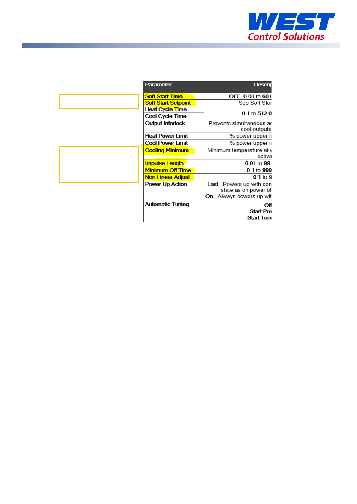
Soft Start parameters
Non-linear Cooling
Extrusion Only Parameters in the Control menu
parameters
59633-MaxVU Rail Full Manual (EN) - Page 65 of 127
Page 66

LM EX AL
Limiter Models
This section applies to the limiter version of the MaxVU Rail (models MVRxTx-xxxx-xxxx).
Introduction to the Limiter model
The Limiter model has fixed output functions.
Depending upon which option is fitted in Output 3 it is Alarm
2 or Retransmit PV.
Refer to the Information menu or check the product label
identify your version.
Output 1. = Limit
Output 2. = Alarm 1
Output 3. If Relay or SSR = Alarm 2 / If Linear = Retransmit PV
The Limiter LEDs have fixed functions: Limit, Exceed & Alarm.
When the PV enters the Exceed condition both the Limit and Exceed LEDs turn ON. Going from the
Exceed condition back into the Safe condition the Exceed LED will turn off but the Limit LED will
stay latched until it is reset. Remember the Limit output itself is energised in Safe condition but deenergises when in the Limit condition.
Navigating is the same as the Standard and Extrusion versions, see General Navigation & Editing,
but for security, users cannot change parameter values such as the Limit Setpoint in the Operator
mode on the Limiter model. These can only change values via the lock code protected Setup or
Advanced Configuration modes.
Warning & Error messages on the Limiter model are similar to the Standard and Extrusion versions,
with the exclusion of control or tuning related messages. On the Limiter, there is the additional
pop-up alert Limit Exceeded message if the process is beyond the limit value set.
Please refer to the Warnings & Messages section.
The Annunciator alarm type, which can be selected for Alarm 1 or Alarm 2, cannot be inhibited.
Limiter Modbus Communications
Please refer to the Commonly Used Modbus Addresses and the Limiter Modbus Addresses for the
Modbus register addresses.
See the Serial Communications for general communications information.
59633-MaxVU Rail Full Manual (EN) - Page 66 of 127
Page 67

Limiter Digital Input
The Digital Input has only one function on the Limiter model. There is no need for a configuration
parameter because it is always a Limit & Alarm Reset. Refer to the Digital Input Operation section.
However, in addition on the Limiter model, if the Digital Input is in an Open state at power-up it
gives a Reset signal.
59633-MaxVU Rail Full Manual (EN) - Page 67 of 127
Page 68

Show
Operator
Alarm State
Latch State
Output Latched
Maximum PV
Screens show the Maximum
Minimum PV
Latch State
Out 1
Out 2
Out 3
Alarm State
Limit
Alarm 2
Loop
Limiter Operator Mode & Screens
PV – top
User Screen
Temperature & Unit – centre & right.
LIM & Limit Setpoint - bottom
Important: Visibility for parameters below must be set to
To clear press then
to select Yes.
Press to accept.
in the
menu.
Alarm triggered
Alarm set, but not triggered
Alarm not set
Latch set, but
output not
Latched
Latch not set
Limiter Output Latching
When an SSR drive or Relay output is configured to ‘latch’ it will remain on after the limit
or alarm condition has cleared. The latch enable parameter, Output Latching, needs to
be ON for outputs you want to latch.
Limiter Clearing Latched Outputs
The latch condition, shown by in the Latch State screen, needs to be cleared either
via a Modbus command, digital input or from the front panel.
To clear latches from the front panel, in the Latch State screen, press then to
select Yes.
Press to accept.
To clear press then to select Yes.
Press to accept.
& Minimum PV reached.
59633-MaxVU Rail Full Manual (EN) - Page 68 of 127
Page 69

Limiter Start-up Latch
The parameter Startup Latch, is only present on the limiter model. It determines how
latching outputs behave when the unit is powered up. It is set individually for each of
the outputs (limit and/or the 2 alarms). The three possible modes are as follows:
• Reset Latch: The latch state is not remembered when the unit is powered off. The
latch becomes active again only if the associated limit / alarm state is present at or
after power-on.
• Always Latch: The instrument will always power on with the chosen output in the
latched state, even if the associated limit or alarm is not active.
• Last Latch: The latch state is remembered on power down. Any output that was
latched on power down it will still be latched when power is restored, even if that limit
or alarm is no-longer active.
Note: If a limit or alarm state exists at power-up, previously unlatched outputs always activate
immediately, no matter how the Start-up Latch has been set.
Limiter Sensor Break Detection
If a “Sensor break” is detected on the Limiter model, this always triggers the Limit exceed
condition, plaice the process into a safe state. Correct the input problem, then unlatch the limit
output to resolve this.
Limiter Output 3 – Linear, Relay or SSR drive
• If the linear output is fitted to Output 3 on the Limiter model, it can only be used for a PV
retransmit function.
• If a relay or SSR drive is fitted in Output 3 then it is fixed as Alarm 2.
59633-MaxVU Rail Full Manual (EN) - Page 69 of 127
Page 70

Parameter
Description
Default Value
* Maximum of 1 decimal place for temperature inputs, in the green square.
J Thermocouple *
-200 – 1200ºC
-128.8 – 537.7ºC
K Thermocouple *
-240 – 1373ºC
-128.8 – 537.7ºC
PT100 *
-199 – 800ºC
-128.8 – 537.7ºC
B Thermocouple
100 – 1824ºC 211 – 3315ºF
C Thermocouple
0 – 2320ºC 32 – 4208ºF
L Thermocouple *
0 – 762ºC
0.0 – 537.7ºC
N Thermocouple
0 – 1399ºC 32 – 2551ºF
R Thermocouple
0 – 1795ºC 32 – 3198ºF
S Thermocouple
0 – 1762ºC 32 – 3204ºF
T Thermocouple *
-240 – 400ºC
-128.8 – 400.0ºC
Limiter Setup mode parameters
If necessary, press & to enter Setup from Operator mode.
Enter Setup Lock-code (default of 10) using and , then press .
1. Some parameters may be hidden depending upon configuration &
hardware.
2. Note the permissible ranges for each temperature sensor type, below.
For example, the B type thermocouple readings cannot have a decimal
point, and it cannot measure below 100 ºC or above 1824 ºC.
3. The number of decimal points is set by the Decimal Place parameter.
The parameters are shown in the following table.
>Input
Type
-328 – 2192ºF
-400 – 2503ºF
-328 – 1472ºF
32 – 1403ºF
-199.9 – 999.9ºF
-199.9 – 999.9ºF
-199.9 – 999.9ºF
K Thermocouple
32.0 – 999.9ºF
59633-MaxVU Rail Full Manual (EN) - Page 70 of 127
Page 71

Parameter
Description
Default Value
-400 – 752ºF
-199.9 – 752.0ºF
Linear dc
0 – 20mA
4 – 20mA
>Input
Scale Range maximum & minimum are only visible when input is a linear dc type.
>Input
>Input
device will limit when PV is greater than the
the Limit
PV Retrans parameters are only visible if Output 3 is Linear.
4
0
1
>PV Retrans
Displayed PV value corresponding to maximum
> PV Retrans
Displayed PV value corresponding to minimum
If a Relay or SSR drive is fitted in Output 3 you will see Alarm 2.
Units
>Input
Decimal Place
Scale Range Maximum
Scale Range Minimum
>Limit
Type
0 – 50mV
0 – 5V
0 – 10V
10 – 50mV
1 – 5V
2 – 10V
°C or °F (not available for Linear dc inputs)
0000 – no decimal point
000.0 – one decimal point
00.00 – two decimal points (linear dc only)
0.000 – three decimal points (linear dc only)
The scaling value for the input range maximum.
The scaling value for the input range minimum.
High –
Limit value. (Exceed condition if PV>Limit Value).
Low - device will limit when PV is less than
value. (Exceed condition if PV<Limit value).
°C
0000
1000
0
High
>Limit
Value
> PV Retrans
Type
Scale Range Maximum
Scale Range Minimum
>Alarm 1
Value
The exceed condition value at which the Limit
output will trip.
0-10V
2-10V
0-20mA
-20mA
-5V
-5V
linear output.
linear output.
Range minimum to range maximum,
or OFF (maximum +1) where OFF disables alarm.
Default alarm type is PV High.
-240
0-10V
1373
-240
1373
59633-MaxVU Rail Full Manual (EN) - Page 71 of 127
Page 72

Parameter
Description
Default Value
>Coms Unit Address
Modbus address from 1 to 255
1
>Coms Baud Rate
1200, 2400, 4800, 9600, 19200 & 38400
9600
>Coms Parity
Odd, Even or None
None
>Alarm 2
Value
Same options as Alarm 1.
Default alarm type is PV Low.
If the Input Type is changed the relevant values from the table above are used for the
Scale Range Maximum and Scale Range Minimum. Review and change if required.
If necessary, press and to clear any Pop Up Alerts.
Press & to exit the Setup mode.
-240
59633-MaxVU Rail Full Manual (EN) - Page 72 of 127
Page 73

Sub-menu Name
1. Input
2. User Calibration
3. Outputs
4. Communication
5. Display
6. Information
Parameter
Description
Default Value
Possible Input types are as listed in the
Display Units either °C or °F.
0000
Maximum allowed
Minimum allowed
Filter Time
OFF or 0.5 to 100.0 seconds in 0.5 increments
2.0
Limiter Advanced Configuration parameters
If necessary, press & to enter Advanced Configuration mode from Operator
mode.
Enter Advanced Lock-code (default of 20) using and , then press .
Limiter - Input Menu
Input Type
Units
Decimal Place
Scale Range Maximum The scaling value for the input range maximum.
Scale Range Minimum The scaling value for the input range minimum.
Limiter Setup mode parameters above
This parameter is hidden when input is a linear
type and °C or °F are hidden from the display.
000.0
00.00 (not for temperature)
0.000 (not for temperature)
K thermocouple
°C
0000
for Input Type.
for Input Type.
59633-MaxVU Rail Full Manual (EN) - Page 73 of 127
Page 74

Parameter
Description
Default Value
Parameter
Description
Default Value
Lower Limit
Upper Limit
Enable Enables the internal thermocouple CJC
(Cold Junction Compensation).
CJC Enable
Disable Disables the internal CJC.
Enable
External compensation must be provided for
thermocouples.
The input scale range, consisting of Scale Range Maximum & Scale Range Minimum above,
is used to narrow the working range (input span) of the controller.
At 5% beyond the scaled range the controller with give over-range or under-range warnings.
For example, a range 0 to 100 gives a span of 100c, so when the PV is >105c the display will
show HIGH.
Limiter - User Calibration Menu
Offset
Low Point
Low Offset
High Point
High Offset
Shifts the input value up or down by a single
offset amount across the entire range.
Enter value at which the low point error was
measured.
Enter equal, but opposite offset value to the
observed low point error.
Enter value at which the high point error was
measured.
Enter an equal, but opposite offset value to the
observed high point error.
Please refer to User Calibration Menu
.
0
0
0
59633-MaxVU Rail Full Manual (EN) - Page 74 of 127
Page 75

Parameter
Description
Default Value
Limit Output
High – device will limit when PV is greater than
ON
OFF
Alarm 1
Sets the alarm switching differential from 0 to full
Limiter - Outputs Menu
Type
Value
the Limit value. (Exceed condition if PV>Limit
Value).
Low - device will limit when PV is less than the
Limit value. (Exceed condition if PV<Limit value).
The exceed condition value at which the Limit
output will trip. Adjustable within the Scaled
Range set in Input.
High
-240
Output Latching
Startup latch
Type
Value
– Limit output latches & needs to be cleared
- Limit output doesn’t latch
Valid only if limit output latching is set to ON
Reset Latch (resets at power on)
Always Latch (latches at power on)
Last Latch (keeps last state at power on)
None
PV High
PV Low
Deviation
Annunciator
Adjustable within the Scaled Range set in Input.
Range minimum to range maximum,
or OFF (maximum +1) where OFF disables alarm.
ON
Last Latch
PV High
1373
Hysteresis
span, on the “safe” side of the alarm point.
Direct - Output active when alarm is active.
Action
Reverse - Output active when alarm is not
active.
59633-MaxVU Rail Full Manual (EN) - Page 75 of 127
1
Direct
Page 76

Parameter
Description
Default Value
ON
OFF
Alarm 2 menu is only shown if Output 3 is Relay or SSR drive.
Alarm 2
None
Adjustable within the Scaled Range set in Input.
Sets the alarm switching differential from 0 to full
Direct - Output active when alarm is active.
ON – Alarm 2 output latches. Reset to continue
OFF
Valid only if Alarm 2 output latching is set to ON
PV Retrans menu is only shown if Output 3 is Linear.
PV Retrans
Output Type
0-10V
Output Latching
Startup latch
Type
Value
Hysteresis
– Alarm 1 output latches. Reset to continue
– Alarm 1 output doesn’t latch
Valid only if Alarm 1 output latching is set to ON
Reset Latch (resets at power on)
Always Latch (latches at power on)
Last Latch (keeps last state at power on)
PV High
PV Low
Deviation
Annunciator
Range minimum to range maximum,
or OFF (maximum +1) where OFF disables alarm.
span, on the “safe” side of the alarm point.
ON
Last Latch
PV Low
-240
Off
Action
Output Latching
Startup latch
Reverse - Output active when alarm not active.
– Alarm 2 output doesn’t latch
Reset Latch (resets at power on)
Always Latch (latches at power on)
Last Latch (keeps last state at power on)
2-10V
0-20mA
4-20mA
0-5V
1-5V
Direct
0-10V
59633-MaxVU Rail Full Manual (EN) - Page 76 of 127
Page 77

Parameter
Description
Default Value
Scale Range Maximum
Display value for maximum output -1999 to 9999
1000
Scale Range Minimum
Display value for minimum output -1999 to 9999
0
Alarm Options
Start-up Inhibit
Inhibit the alarm(s) on Start up :-
Sensor Break
Either OFF or ON.
Parameter
Description
Default Value
Unit Address
Modbus address from 1 to 255
1
Baud Rate
Coms data rate in kbps
Parity
Parity checking: Odd, Even or None.
None
Parameter
Description
Default Value
10
20
5
English
Used to reset all parameters back to the factory defaults.
See
None
Alarm 1
Alarm 2
Alarm 1 & 2
None
ON - triggers Alarm output(s) when sensor break
is detected.
Limiter - Communications Menu
1200, 2400, 4800, 9600, 19200 & 38400.
Limiter - Display Menu
Setup Unlock Code
Advanced Unlock
Code
Screen Timeout Screensaver time. Display turns off after 5, 15 or 30 mins.
View & adjust Setup mode lock code (password).
From 1 to 9999 or Off for no lock code.
View & adjust Advanced mode lock code (password).
From 1 to 9999 or Off for no lock code.
ON
9600
Selected language Display language – English, German or French.
Reset to Defaults
MaxVU Rail Factory Defaults.
59633-MaxVU Rail Full Manual (EN) - Page 77 of 127
Page 78

Parameter
Description
Comm
RS485 communications option - Fitted or None.
Limiter - Information Menu
PRL
DOM
FW Version
The hardware/software revision level. Shows the product update status.
Date of manufacture in the form of month and year, mmyy.
The firmware version number & code type.
FW Type
Serial Serial Number of unit.
Out1
Out2
Out3
DI
Shows factory fitted hardware options –
Output 1 can be: SSR (SSR driver) or Relay
Output 2 can be: SSR (SSR driver) or Relay
Output 3 can be: None, SSR (SSR driver), Relay or Linear
Digital Input is isolated or not - Iso or NonIs – see the Isolation Chart
Limiter - Exiting from Advanced Configuration mode
If necessary, press and to clear any Pop-Up Alerts.
Press & to exit up one menu level. Repeat if required.
Some menus have sub-menus so it may be necessary to press this key combination more than
once. For example, to go back to the Operator screen from inside the Output 2 sub-menu you
need to go up 3 levels and then press & to exit the Advanced Configuration mode.
59633-MaxVU Rail Full Manual (EN) - Page 78 of 127
Page 79

MaxVU / MaxVU Rail Configurator PC Software
MaxVU Configurator PC software available to download from www.west-cs.com.
A variant of the Universal Configuration Adaptor is available to connect to the front configuration
port on MaxVU and MaxVU Rail. Order code CONV-BA-00-00-00-MV from your supplier.
The software can be used ‘offline’ to create/edit configuration files for later use.
To up/download settings or update firmware your unit must be powered-up, and
connected to your PC using the configuration cable/adaptor to the device’s
configuration port, or a via a working RS485 serial communications link.
- Specify your hardware – used to define your hardware set up if you are not currently
connected to the target instrument. Use if you can’t ‘Detect Hardware’.
- Wizard – this is a comprehensive wizard to make the setting up process easier.
- Open, Save and Print. - Read or Write to an instrument.
- Settings. - Language (MaxVU Rail only). - Splash screen (MaxVU Rail only).
59633-MaxVU Rail Full Manual (EN) - Page 79 of 127
Page 80

Select the correct type/model from the list
E.g. Select MaxVU Rail Standard then press .
Read in Your Hardware
If you are working online with your instrument,
press , then check and adjust Units’ Communication Port, the PC COM port
number, and if using RS485, enter the correct Address,
Baudrate, Databits and Parity (as currently setup in your
instrument).
Then press to read in your MaxVU Rail’s hardware
options.
This step reads in the hardware settings from the
connected unit but not the parameter settings.
59633-MaxVU Rail Full Manual (EN) - Page 80 of 127
Page 81

Read in Parameter Configuration
Before reading in the parameters, first upload the hardware options (see above).
Then press to read in the current settings from the unit.
Make Configuration Changes
Edit the configuration to your requirements.
Write to Unit
Press to download your new configuration to the unit.
Save Changes to File
Press to save any changes to a file if you wish to use it later.
Loading in Older Configuration Files
The MaxVU configurator may give a
warning when loading in a file from older
versions of the configurator.
If you open this file you need to consider that the Unit Information-Details section may not be
complete or correct.
Opening files in older versions of
the configurator will not give a
warning message but can give
misleading information in the
Details.
For example, see screenshot
where the DoM is July 2014.
59633-MaxVU Rail Full Manual (EN) - Page 81 of 127
Page 82

Model
Firmware Name
Standard
V227E_Encrypt.s19
Extrusion
V227F_Encrypt.s19
Limiter
V227G_Encrypt.s19
Firmware and Language Updating
If advised by the factory or your authorised supplier, you can upgrade the firmware in the
connected instrument by pressing . Set the communications parameters (see above), then
press the button.
Follow the on-screen instructions, ensuring you select the correct type and version of firmware file
(*.s19) for your MaxVU Rail type.
If you are uploading language files (MaxVU Rail only) the version needs to match the firmware.
59633-MaxVU Rail Full Manual (EN) - Page 82 of 127
Page 83

Serial Communications
Supported Protocol
The unit supports Modbus RTU protocol through the RS485 interface. For a complete description of
the Modbus protocol refer to the description provided at http://www.modbus.org/
RS485 Configuration
The RS485 address, bit rate and character format are configured via the front panel from the
Communications Sub-menu.
Data rate: 4800, 9600 (default), 19200 or 38400 bps
Parity: None (default), Even or Odd
Device Address: 1 to 255 - See RS485 Device Addressing
The following communication parameters are fixed:
Start bits: Always 1 bit.
Stop bits: Always 1 bit.
Character format: Always 8 bits per character (1 byte).
For successful communication, the master device must have matching communications
settings. We do not advise connecting via both the bus connection and the top RS485 at
the same time.
When using the PC configuration software via the
configuration port, you only need to select the correct
PC COM port number. All other parameters are fixed
(Device Address=1, Baudrate=19200, Databits=8 and
Parity=None).
RS485 Device Addressing
The instrument must be assigned a unique device address in the range 1 to 255. This address is
used to recognise Modbus queries intended for this instrument.
Except for globally addressed broadcast messages sent to device address 0, the instrument
ignores Modbus queries from the master that do not match the address that has been assigned to
it. These global queries are processed when received but no response messages are returned.
59633-MaxVU Rail Full Manual (EN) - Page 83 of 127
Page 84

Address
Function
Data
CRC Check
MODBUS
SLAVE
QUERY
RESPONSE
Link Layer
A Query (or command) is transmitted from the Modbus Master to the Modbus Slave. The slave
instrument assembles the reply to the master.
MASTER
INSTRUMENT
A message for either a QUERY or RESPONSE is made up of an inter-message gap followed by a
sequence of data characters. The inter-message gap is at least 3.5 data character times - the
transmitter must not start transmission until 3 character times have elapsed since reception of the
last character in a message, and must release the transmission line within 3 character times of the
last character in a message.
Three character times is approximately 0.75ms at 38400 bps, 1.5ms at 19200 bps, 3ms at
9600 bps and 6ms at 4800bps.
Data is encoded for each character as binary data, transmitted LSB first.
For a QUERY the address field contains the address of the slave destination. The slave address is
given together with the Function and Data fields by the Application layer. The CRC is generated
from the given address, function and data characters.
For a RESPONSE the address field contains the address of the responding slave. The Function and
Data fields are generated by the slave application. The CRC is generated from the address,
function and data characters.
The standard MODBUS RTU CRC-16 calculation employing the polynomial 2
Inter-message gap
1 character
1 character
n characters
59633-MaxVU Rail Full Manual (EN) - Page 84 of 127
16+215+22
+1 is used.
2 characters
Page 85

Function Code
Modbus Meaning
Description
03 (0x03)
Read Holding Registers
Read current binary value of specified number of
06 (0x06)
Write Single Holding
Writes 2 bytes to a specified word address.
08 (0x08)
Diagnostics
Used for loopback test only to check the
16 (0x10)
Write Multiple Holding
Writes up to 253 bytes of data to the specified address
QUERY
Function
Address of 1st Word
Number of Words
03 / 04
HI
LO
HI
LO RESPONSE
Function
Number of
First Word
Last Word
03 / 04
n
HI
LO
HI
LO
Supported Modbus Functions
The following Modbus function types are supported by this instrument:
decimal
(hexadecimal)
04 (0x04)
Read Input Registers
parameters at given address.
Up to 64 parameters can be accessed with one query.
Register
communications work.
Registers
range.
Function Descriptions
The following is interpreted from the Modbus Protocol Description obtainable from
http://www.modbus.org/
.
In the function descriptions below, the preceding device address value is assumed, as is the
correctly formed two-byte CRC value at the end of the QUERY and RESPONSE frames.
Function 03 / 04 - Read Holding/Input Registers
Reads the current binary value of data at the specified word addresses.
Bytes
In the response, the “Number of Bytes” ‘n’, indicates the number of data bytes read from the
instrument. E.g. if 5 words are read, the count will be 10 (A hex). The maximum number of words
that can be read is 64. If a parameter does not exist at one of the addresses read, then a value of
0000h is returned for that word.
59633-MaxVU Rail Full Manual (EN) - Page 85 of 127
Page 86

QUERY
Function
Diagnostic Code
Value
06
HI =00
LO=00
HI
LO RESPONSE
Function
Sub-function
Value
06
HI=00
LO=00
HI
LO
QUERY
Function
Diagnostic Code
Value
08
HI =00
LO=00
HI
LO RESPONSE
Function
Sub-function
Value
08
HI=00
LO=00
HI
LO
QUERY
Function
1st Write
Number of
Number of
10
HI
LO
HI
LO →
RESPONSE
Function
1st Word Address
Number of Words
10
HI
LO
HI
LO
Function 06 – Write Single Register
Function 08 - Loopback Diagnostic Test
The Response normally returns the same data as the loopback query itself and so can
be used to test the communications. Other Diagnostic Codes are not supported.
Function 16 (0x10 Hex) - Write Multiple Registers
Writes consecutive word (two-byte) values starting at the specified address.
Address
Words to
Write
Query Bytes
1st Query
Byte
2nd Query
Byte
etc
Last Query
Byte
The number of data bytes that can be written in one message is 253 bytes.
59633-MaxVU Rail Full Manual (EN) - Page 86 of 127
Page 87

Name
Dec
Hex
Access
Comments
Actual effective setpoint (e.g. instantaneous value when
setpoint in ramping). Not applicable for limiter
Target controller Setpoint, settable within setpoint
upper/lower limit values. Not applicable for limiter
The ‘Exceed’ value at which the limit output will trip.
Settable within the input range. Limiter only.
Limit Exceed Status
1492
5D4
RO
0 = Limit value not exceeded, 1 = Limit value exceeded
Alarm 1 Value
1402
57A
R/W
Alarm 1 value. Limited by the input span
Alarm 2 Value
1406
57E
R/W
Alarm 2 value. Limited by the input span
Alarm 1 Status
1470
5BE
RO
0 = Alarm 1 inactive, 1 = Alarm 1 active
Alarm 2 Status
1471
5BF
RO
0 = Alarm 2 inactive, 1 = Alarm 2 active
A bit mask where bit 1 = Output 1 latched, bit 2 =
00000101 = outputs 1 & 3 are latched
1 = Attempts to reset all latched outputs (effect is
subject to process conditions)
Sensor Break Status
1072
430
RO
0 = Ok, 1 = Sensor Break
0 = Control Disabled, 1 = Control Enabled
Not applicable to Limiter model
0 = Control Disabled, 1 = Control Enabled
Not applicable to Limiter model
0 = Automatic Control, 1 = Manual Control
Not applicable to Limiter model.
A read only combined heat/cool power level in
Not applicable to Limiter model.
0-100% heating/primary power. Not applicable on
Limiter
0-100% cooling/secondary power. Not applicable on
Limiter
Read: 0 = Inactive, 1 = PreTune Active 2 = Tune at SP
SP
Modbus Addresses
Register addresses are given in Decimal and Hexadecimal formats.
Parameter access can be Read Only (RO), Write Only (WO) or Read & Write (R/W)
Commonly Used Modbus Addresses
Process Variable 1070 42E RO Read process variable value
Actual Setpoint 1270 4F6 RO
Setpoint 1200 4B0 R/W
Limit Value 1481 5C9
R/W
Output Latch Status 1170 47F RO
Latch Reset 1151 492 WO
Control Enable/Disable 1375 55F R/W
Control Enable State 1376 560 RO
Manual Power Enable 1315 523 R/W
Combined Power (Manual Power
in Manal Mode)
Heat Power Output (Primary) 1370 55A RO
Cool Power Output (Secondary) 1371 55B RO
Automatic Tuning 1384 568
1316 524 RO/RW
R/W
Output 2 latched, bit 3 = Output 3 latched. E.g. binary
automatic mode, or used to write the power level in
manual mode.
-100 (max cooling) to 100 (max heating)
Active
Write: 0 = Stop Tune, 1 = Run PreTune 2 = Run Tune at
59633-MaxVU Rail Full Manual (EN) - Page 87 of 127
Page 88

1070
Operator/User
1072
Digital Input Status
Operator/User
1075
433
RO
0 = Off, 1 = On
1 = Attempts to reset all latched
conditions)
Operator/User
1171
Operator/User
1172
Operator/User
Operator/User
1175
Operator/User
1178
Operator/User
1181
Operator/User
Standard and Extrusion Modbus Addresses
Name HMI Mode Dec Hex Access Comments
Process Variable Operator/User
Sensor Break Status
42E RO Read process variable value
430 RO 0 = Ok, 1 = Sensor Break.
Alarm 1 Status
Alarm 2 Status
Latch Reset
Output Latch Status
Output 1 Latch Status
Output 2 Latch Status
Output 3 Latch Status
Output 1 Status
Output 2 Status
Output 3 Status
Actual Setpoint
Operator/User
Operator/User
Operator/User
Operator/User
Operator/User
1470 5BE RO 0 = Alarm 1 inactive, 1 = Alarm 1 active
1471 5BF RO 0 = Alarm 2 inactive, 1 = Alarm 2 active
1151 492 WO
1170 47F RO
47F RO 0 = Output 1 not latched, 1 = latched
47F RO 0 = Output 2 not latched, 2 = latched
1173 47F RO 0 = Output 3 not latched, 3 = latched
47F RO 0 = Output 1 OFF, 1 = ON
47F RO 0 = Output 2 OFF, 1 = ON
47F RO 0 = Output 3 OFF, 1 = ON
1270 4F6 RO
outputs (effect is subject to process
A bit mask where bit 1 = Output 1
latched, bit 2 = Output 2 latched, bit 3 =
Output 3 latched. E.g. binary 00000101
= outputs 1 & 3 are latched
Actual effective setpoint (e.g.
instantaneous value when setpoint in
ramping). Not applicable for limiter,
Manual Power Enable
Combined Power
(or Manual mode power value)
Heat Power Output (Primary)
Cool Power Output (Secondary)
1315 523 R/W 0 = Automatic, 1 = Manual Control
A read only combined heat/cool power
level in automatic mode (or used to
write the power level in manual mode).
-100 (max cooling) to 100 (max heating)
Not applicable to Limiter model.
0-100% heating/primary power. Not
applicable on Limiter
0-100% cooling/secondary power. Not
applicable on Limiter
Operator/User
Operator/User
Operator/User
1316 524
1370 55A RO
1371 55B RO
RO
(RW)
59633-MaxVU Rail Full Manual (EN) - Page 88 of 127
Page 89

Sets the function digital input controls:
5 - Tune at SP Stop (High) / Start (Low)
Cold Junction Compensation
Input
1006
3EE
R/W
0 = Cold Junction Disabled, 1 = Enabled
0 (OFF) or 5 to 1000 = Input filter time
increments
Max working temperature, or display
value for the max linear input level
Min working temperature, or display
value for the min linear input level
The number of decimal places
3 – X.XXX (linear inputs only)
Input Units
Input
1005
3ED
R/W
0 = Deg C, 1 = Deg F
Name HMI Mode Dec Hex Access Comments
Control Enable/Disable
Control Enable State
Digital Input Function Input 1007 3EF
Filter Time Input 1004 3EC
Scale Range Lower Limit Input 1002 3EA
Scale Range Upper Limit Input 1001 3E9
Decimal Point Position Input 1003 3EB
Operator/User
Operator/User
1375 55F R/W 0 = Control Disable, 1 = Control Enable
1376 560 RO
R/W
R/W
R/W
R/W
R/W
0 = Control Disabled, 1 = Control
Enabled
0 - No Action (Default)
1 - Alarm Reset (High)
2 - Control Enable (High) / Disable (Low)
3 - Control Auto (High) / Manual (Low)
4 - Pre-tune Stop (High) / Start (Low)
OFF or 0.5 to 100.0 seconds, in 0.5s
displayed:
0 - XXXX
1 – XXX.X
2 – XX.XX (linear inputs only)
59633-MaxVU Rail Full Manual (EN) - Page 89 of 127
Page 90

Value
Range
0
J Thermocouple
1
K Thermocouple
2
PT100
3
B Thermocouple
4
C Thermocouple
5
L Thermocouple
6
N Thermocouple
7
R Thermocouple
8
S Thermocouple
9
T Thermocouple
10
0 – 20mA
11
4 – 20mA
12
0 – 50mA
13
10 – 50mA
14
0 – 5V
15
1 – 5V
16
0 – 10V
17
2 – 10V
1605
R/W
The adjustment point: Input range
maximum to input range minimum
User Low Calibration Offset
User Calibration
1603
643
R/W
The required adjustment +/- Span
The adjustment point: Input range
maximum to input range minimum
1601
R/W
Possible types. Valid if linear output
5 = 1-5V
PV or SP value where retransmit output
Adjustable from -1999 to 9999
PV or SP value where retransmit output
20). Adjustable from -1999 to 9999
Name HMI Mode Dec Hex Access Comments
Input Type Input 1000 3E8
R/W
User High Calibration Offset User Calibration
645
User High Calibration Point User Calibration 1604 644
User Low Calibration Point User Calibration 1602 642
User Single Point Offset User Calibration
641
Linear Output 3 Type Outputs 1140 474
Linear Out 3 Scale Maximum Outputs 1141 475
Linear Out 3 Scale Minimum Outputs 1142 476
R/W
R/W
R/W
R/W
R/W
The required adjustment +/- Span
The required adjustment +/- Span
fitted.
1 = 0-10V
2 = 2-10V
3 = 0-20mA
4 = 4-20mA
0 = 0-5V
is at min level (e.g. 4mA if type is 4-20).
is at max level (e.g. 20mA if type is 4-
59633-MaxVU Rail Full Manual (EN) - Page 90 of 127
Page 91

If Relay/SSR fitted:
8 = Retransmit Process value
0 = Sync with output, 1 = Opposite to
output (e.g. ON when output off)
0 = Off, 1 = On (will latch on when
active)
0 = Direct, 1 = Reverse (off if alarm
active)
0 = Sync with output, 1 = Opposite to
output (e.g. ON when output off)
0 = Off, 1 = On (will latch on when
active)
0 = Direct, 1 = Reverse (off if alarm
active)
0 = Sync with output, 1 = Opposite to
output (e.g. ON when output off)
0 = Off, 1 = On (will latch on when
active)
0 = Direct, 1 = Reverse (off if alarm
active)
0 = Heat Output
6 = Loop Alarm
Name HMI Mode Dec Hex Access Comments
0 = Heat Output
1 = Cool Output
2 = Non-Linear Cooling – Only Extrusion
3 = Alarm 1
4 = Alarm 2
5 = Alarm 1 or Alarm 2
Output 3 Usage Outputs 1130 46A
Output 3 Indicator Invert Outputs 1131 46B
Output 3 Alarm Latching Outputs 1133 46D
Output 3 Alarm Action Outputs 1132 46C
R/W
R/W
R/W
R/W
6 = Loop Alarm
If Linear out fitted:
0 = Heat Output
1 = Cool Output
7 = Retransmit Setpoint
Output 2 Indicator Invert Outputs 1121 461
Output 2 Alarm Latching Outputs 1123 463
Output 2 Alarm Action Outputs 1122 462
Output 2 Usage Outputs 1120 460
Output 1 Indicator Invert Outputs 1101 44D
Output 1 Alarm Latching Outputs 1103 44F
Output 1 Alarm Action Outputs 1102 44E
Output 1 Usage Outputs 1100 44C
R/W
R/W
R/W
R/W
R/W
R/W
R/W
R/W
0 = Heat Output
1 = Cool Output
2 = Non-Linear Cooling – Only Extrusion
3 = Alarm 1
4 = Alarm 2
5 = Alarm 1 or Alarm 2
6 = Loop Alarm
1 = Cool Output
2 = Non-Linear Cooling – Only Extrusion
3 = Alarm 1
4 = Alarm 2
5 = Alarm 1 or Alarm 2
59633-MaxVU Rail Full Manual (EN) - Page 91 of 127
Page 92

Read: 0 = Inactive, 1 = PreTune Active 2
= Run Tune at SP
On power-up control enable/disable is:
0=Last State, 1=Always Enabled
R/W
Heat Power Limit
Control
1311
51F
R/W
Sets limit from 0-100% Heating
0=Interlock Off or 1=Interlock On (On
Do not use if PB ‘overlap’ has been set
Biases the working point 0% to 100%
or -100 to +100% for dual control
R/W
In display unit, values from -20% to 20%
proportional band values
1- 5999 seconds (used in manual mode
if loop alarm has been configured
Derivative Time (Rate)
Control
1305
519
R/W
0 (Off) or 1 to 5999 seconds
1304
R/W
Name HMI Mode Dec Hex Access Comments
Automatic Tuning Control 1384 568
Tune Status / Error Messages Control 1378 562
Power Up Action Control 1377 561
R/W
RO
R/W
= Tune at SP Active
Write: 0 = Stop Tune, 1 = Run PreTune 2
0= No tuning active
1= Tuning active
2= PV within 5% of setpoint
3= Setpoint is Ramping
4= Control On/Off
5= Manual Control
6= Pulse Tune Error
7= Sensor Break
8= Timer running
9= Control disabled
10= Setup not completed
Cool Power Limit Control 1312 520
Output Interlock Control 1185 4A1
Cool Cycle Time Control 1318 526
Heat Cycle Time Control 1317 525
Bias (Manual Reset) Control 1307 51B
On/Off Differential Control 1308 51C
Overlap/Deadband Control 1306 51A
Loop Alarm Time Control 1310 51E
Integral Time (Automatic Reset) Control
Cool Proportional Band Control 1303 517
518
R/W
R/W
R/W
R/W
R/W
R/W
R/W
Sets limit from 0-100% cooling
prevents simultaneous heating &
cooling)
0 (OFF) or 1 to 5120 = Cycle time OFF or
0.1 to 512.0 seconds, in 0.1s increments
0 (OFF) or 1 to 5120 = Cycle time OFF or
0.1 to 512.0 seconds, in 0.1s increments
0.1% to 10.0% of input span
of combined primary and secondary
0 (Off) or 1 to 5999 seconds
0 = On/Off control, or 1 to 9999 cooling
band, in display units (e.g. = 0.001 to
9.999 if display has 3 decimal places)
Heat Proportional Band Control 1302 516
0 = On/Off control, or 1 to 9999 heating
R/W
band, in display units (e.g. = 0.001 to
9.999 if display has 3 decimal places)
59633-MaxVU Rail Full Manual (EN) - Page 92 of 127
Page 93

Setpoint during Soft Start. Settable
values. Extrusion model only
0 = Soft Start Off, or 1 to 3600 minutes
duration. Extrusion model only
Soft Start Time Remaining
Control
1292
50C
RO
Extrusion model only
RO
Offset the entered SP by -1999 to 9999
setpoint limits.
Target controller Setpoint value,
limit values
Minimum value for target Setpoint.
does not limit effective SP with ‘Offset’
Maximum value for target Setpoint.
does not limit effective SP with ‘Offset’
Time the setpoint is maintained (the
model only.
The rate from 1 to 9999 display units
(SP steps straight to the target value)
Time from power-up or control enable
5999 minutes, 0 = No Delay.
0 = Delay & On-Timer disabled, 1 =
Enabled. Standard model only
0 = Off, 1 = Detected break always
condition is also an alarm condition.
Name HMI Mode Dec Hex Access Comments
Soft Start Setpoint Control 1290 50A
Soft Start Time Control 1291 50B
R/W
R/W
within setpoint upper/lower limit
Soft Start Time Remaining Secs Control 1293 50D
Soft Start Time Remaining = ( (Soft Start Time Remaining – 1) + Soft Start Time Remaining Secs)
Setpoint Offset Setpoint 1205 4B5
Setpoint Setpoint 1200 4B0
Setpoint Lower Limit Setpoint 1202 4B2
Setpoint Upper Limit Setpoint 1201 4B1
Timer On-Time Setpoint 1277 4FD
R/W
R/W
R/W
R/W
R/W
Extrusion model only
Effective SP = SP+Offset. NOTE:
effective SP is not limited by the
settable within setpoint upper/lower
Adjustable within scale range. NOTE:
Adjustable within scale range. NOTE:
‘dwell’ after any delay or ramp). Set 1
to 5999 minutes, 0 = No Dwell. Control
is disabled when Dwell ends. 6000 =
Infinite Dwell. Standard controller
Setpoint Ramp Rate Setpoint 1204 4B4
Delayed Start Time Value Setpoint 1276 4FC
Timer Enable Setpoint 1275 4FB
Sensor Break Activate Alarm Alarms 1409 581
R/W
R/W
R/W
R/W
for ‘ramping’ the setpoint. 10000 = Off
before control actually begins. Set 1 to
activates both alarms (if configured).
If Off, alarms only activate if break
59633-MaxVU Rail Full Manual (EN) - Page 93 of 127
Page 94

While display is active, this alternates
3 = Alarm 1 or Alarm 2
Set alarms to Inhibit at power-up or
3 = Both Alarms
Alarm 2 switching hysteresis. Limited by
the input span
Alarm 2 value. Limited by the input
span
0 = None (alarm not used)
4 = Band Alarm
Alarm 1 switching hysteresis. Limited by
the input span
Alarm 1 value. Limited by the input
span
0 = None (alarm not used)
4 = Band Alarm
Parity
Communications
1501
5DD
R/W
0 = None, 1 = Even, 2 = Odd
0 = 1200 bps
5 = 38400 bps
Unique instrument network address
from 1 to 255
Language selection. 0 = English, 1 = The
installed alternative language
The Installed alternative language. 00 =
German, 01 = English, 02 = French
0 = 5mins, 1 = 15mins & 2 = 30mins
without keypress before timeout
0 = Off, 1 = Hide setpoint on display,
but control functions are still active.
Name HMI Mode Dec Hex Access Comments
‘Alarm’ with PV value if selected
alarm(s) are active. Red alarm output
Alarm Notification Alarms 1408 580
Alarm Inhibit Alarms 1410 582
Alarm 2 Hysteresis Alarms 1407 57F
Alarm 2 Value Alarms 1406 57E
Alarm 2 Type Alarms 1404 57C
R/W
R/W
R/W
R/W
R/W
LEDs are not affected.
0 = None, 1 = Alarm 1, 2 = Alarm 2,
controller setpoint change.
0 = None, 1 = Alarm 1, 2 = Alarm 2
1 = High Alarm
2 = Low Alarm
3 = Deviation
Alarm 1 Hysteresis Alarms 1403 57B
Alarm 1 Value Alarms 1402 57A
Alarm 1 Type Alarms 1400 578
Baud Rate Communications 1502 5DE
Modbus Address Communications 1500 5DC
Selected Language Display 1828 724 R/W
Alternative Language Display 1808 710
R/W
R/W
R/W
R/W
R/W
RO
1 = High Alarm
2 = Low Alarm
3 = Deviation
1 = 2400 bps
2 = 4800 bps
3 = 9600 bps
4 = 19200 bps
Screen Timeout Display 1830 726
Transmitter View Enable Display 1806 70E
R/W
R/W
59633-MaxVU Rail Full Manual (EN) - Page 94 of 127
Page 95

The password to enter the Advanced
Menu 0 = Off, or 1 to 9999
2207
R/W
2206
R/W
2205
R/W
0 = Hide, 1 = Show control
enable/disable
2203
R/W
Unhide Alarm Latch
Operator
2202
89A
R/W
0 = Hide, 1 = Show alarm latch screen
2201
R/W
2200
R/W
Encoding e.g. 0403 for April 2003 is
returned as 193 hex.
Serial Number High
Information
504
1F8
RO
First four digits, aaaa, bits 32-47
503
RO
Serial Number Low
Information
502
1F6
RO
Last four digits, cccc, bits 0-15
Firmware Type Low
Information
65451
FFAB
RO
(e.g. 227E). Returned as ascii
65450
RO
Firmware Version High
Information
65458
FFB2
RO
(e.g. 10p12). Returned as ascii
65457
RO
Firmware Version Low Mid
Information
65456
FFB0
RO
(e.g. 10p12). Returned as ascii
65455
RO
603
RO
Option 3
Information
602
25A
RO
0= None, 1= Relay, 5= Linear
601
RO
Option 1
Information
600
258
RO
0= None, 1= Relay, 3= SSR
511
RO
Variant
Information
510
1FE
RO
1= Standard, 0= Extrusion, 2= Limit
509
RO
Name HMI Mode Dec Hex Access Comments
Advanced Lock Code Display 1803 70B
Setup Lock Code Display 1804 70C
Unhide Delay Time Remaining Operator
Unhide Time On Remaining Operator
Unhide Manual Control Enable Operator
Unhide Control Enable Operator 2204 89C
Unhide Alarm Status Operator
Unhide PV Min Operator
Unhide PV Max Operator
Date Of Manufacture Information 505 1F9
Serial Number formed of aaaa bbbb cccc (12 BDC digits):
89F
89E
89D
89B
899
898
R/W
R/W
R/W
RO
The password to enter the Setup Menu
0 = Off, or 1 to 9999
0 = Hide, 1 = Show remaining time
0 = Hide, 1 = Show remaining time
0 = Hide, 1 = Show auto/manual select
0 = Hide, 1 = Show alarm status
0 = Hide, 1 = Show stored minimum PV
0 = Hide, 1 = Show stored maximum PV
Serial Number Mid Information
PRL Information 506 1FA
Firmware Type High Information
Firmware Version Mid Information
Firmware Version Low Information
Communications Option (RS485) Information
Option 2 Information
Supply Voltage Information
Digital Input Information
1F7
FFAA
FFB1
FFAF
25B
259
1FF
1FD
RO
Middle four digits, bbbb, bits 16-31
Formatted as high byte hardware
number as integer [0-99], low byte ascii
character [A-Z] for software
(e.g. 227E). Returned as ascii
(e.g. 10p12). Returned as ascii
(e.g. 10p12). Returned as ascii
0 = Not Fitted, 1 = Fitted.
0= None, 1= Relay, 3= SSR
0= 240V, 1= Low Voltage
0= Non-isolated, 1= Isolated.
59633-MaxVU Rail Full Manual (EN) - Page 95 of 127
Page 96

1070
Operator/User
1072
0 = Limit value not exceeded, 1 = Limit
value exceeded
Alarm 1 Status
Operator/User
1470
5BE
RO
0 = Alarm 1 inactive, 1 = Alarm 1 active
Operator/User
1471
The function digital input controls:
1 – Limit & Alarm Reset (High)
Cold Junction Compensation
Input
1006
3EE
R/W
0 = Cold Junction Disabled, 1 = Enabled
0 (OFF) or 5 to 1000 = Input filter time
increments
Max working temperature, or display
value for the max linear input level.
Min working temperature, or display
value for the min linear input level.
The number of decimal places displayed:
3 – X.XXX (linear inputs only)
Input Units
Input
1005
3ED
R/W
0 = Deg C, 1 = Deg F
Limiter Modbus Addresses
Name HMI Mode Dec Hex Access Comments
Process Variable Operator/User
Sensor Break Status
42E RO Read process variable value
430 RO 0 = Ok, 1 = Sensor Break.
Limit Exceed Status
Alarm 2 Status
Operator/User
1492 5D4 RO
5BF RO 0 = Alarm 2 inactive, 1 = Alarm 2 active
Name HMI Mode Dec Hex Access Comments
Digital Input Function Input 1007 3EF
Filter Time Input 1004 3EC
Scale Range Lower Limit Input 1002 3EA
Scale Range Upper Limit Input 1001 3E9
Decimal Point Position Input 1003 3EB
R/W
R/W
R/W
R/W
R/W
0 - No Action
OFF or 0.5 to 100.0 seconds, in 0.5s
0 - XXXX
1 – XXX.X
2 – XX.XX (linear inputs only)
59633-MaxVU Rail Full Manual (EN) - Page 96 of 127
Page 97

Value
Range
0
J Thermocouple
1
K Thermocouple
2
PT100
3
B Thermocouple
4
C Thermocouple
5
L Thermocouple
6
N Thermocouple
7
R Thermocouple
8
S Thermocouple
9
T Thermocouple
10
0 – 20mA
11
4 – 20mA
12
0 – 50mA
13
10 – 50mA
14
0 – 5V
15
1 – 5V
16
0 – 10V
17
2 – 10V
User High Calibration Offset
User Calibration
1605
645
R/W
The required adjustment +/- Span
The adjustment point: Input range
maximum to input range minimum
R/W
The adjustment point: Input range
maximum to input range minimum
User Single Point Offset
User Calibration
1601
641
R/W
The required adjustment +/- Span
0 = Off, 1 = Detected break always
condition is also an alarm condition.
Set to inhibit alarms at power-up.
3 = Both Alarms
Alarm 2 switching hysteresis. Limited by
the input span
R/W
0 = None (alarm not used)
4 = Annunciator
Alarm 1 switching hysteresis. Limited by
the input span
Name HMI Mode Dec Hex Access Comments
Input Type Input 1000 3E8
R/W
User High Calibration Point User Calibration 1604 644
User Low Calibration Offset User Calibration 1603 643
User Low Calibration Point User Calibration 1602 642
Sensor Break Activate Alarm Alarms 1409 581
Alarm Inhibit Alarms 1410 582
Alarm 2 Hysteresis Alarms 1407 57F
Alarm 2 Value Alarms 1406 57E
Alarm 2 Type Alarms 1404 57C
Alarm 1 Hysteresis Alarms 1403 57B
R/W
R/W
R/W
R/W
R/W
R/W
R/W
The required adjustment +/- Span
activates both alarms (if configured).
If Off, alarms only activate if break
0 = None, 1 = Alarm 1, 2 = Alarm 2
Alarm 2 value. Limited by the input span
1 = High Alarm
2 = Low Alarm
3 = Deviation
59633-MaxVU Rail Full Manual (EN) - Page 97 of 127
Page 98

Alarm 1 Value
Alarms
1402
57A
R/W
Alarm 1 value. Limited by the input span
1480
R/W
PV value where retransmit output is at
Adjustable from -1999 to 9999
PV value where retransmit output is at
Adjustable from -1999 to 9999
0 = Sync with output, 1 = Opposite to
output (e.g. ON when output off)
1133
R/W
1132
R/W
0 = Sync with output, 1 = Opposite to
output (e.g. ON when output off)
0 = Reset Latch (resets at power on)
on)
Name HMI Mode Dec Hex Access Comments
0 = None (alarm not used)
1 = High Alarm
Alarm1Type Outputs 1400 578
Limit Startup Latch Outputs 1104 450
Limit Value Outputs 1481 5C9
Limit Type Outputs
Linear Type Outputs 1140 474
5C8
R/W
R/W
R/W
R/W
2 = Low Alarm
3 = Deviation
4 = Annunciator
0 = Reset Latch (resets at power on)
1 = Always Latch (latches at power on)
2 = Last Latch (keep last state at power
on)
The ‘Exceed’ value at which the limit
output will trip. Settable within the input
range.
0 = High Limit Action, 1 = Low Limit Action
PV Retransmit
Possible types. Valid if linear output
fitted.
0=0-5V
1=0-10V
2=2-10V
3=0-20mA
4=4-20mA
5=1-5V
Linear Out 3 Scale Maximum Outputs 1141 475
Linear Out 3 Scale Minimum Outputs 1142 476
Output 3 Indicator Invert Outputs 1131 46B
Alarm 2 StartUp Latch Outputs 1134 46E
Output 3 Alarm Latching Outputs
Output 3 Alarm Action Outputs
Output 2 Indicator Invert Outputs 1121 461
Alarm 1 Startup Latch Outputs 1124 464
46D
46C
R/W
R/W
R/W
R/W
R/W
R/W
min level (e.g. 4mA if type is 4-20).
max level (e.g. 20mA if type is 4-20).
0 = Reset Latch (resets at power on)
1 = Always Latch (latches at power on)
2 = Last Latch (keep last state at power
on)
0 = Off, 1 = On (will latch on when active)
0 = Direct, 1 = Reverse (off if alarm active)
1 = Always Latch (latches at power on)
2 = Last Latch (keep last state at power
59633-MaxVU Rail Full Manual (EN) - Page 98 of 127
Page 99

Output 2 Alarm Latching
Outputs
1123
463
R/W
0 = Off, 1 = On (will latch on when active)
1122
R/W
0 = Sync with output, 1 = Opposite to
output (e.g. ON when output off)
Limit Output 1 Latching
Outputs
1103
44F
R/W
0 = Off, 1 = On (will latch on when active)
Parity
Communications
1501
5DD
R/W
0 = None, 1 = Even, 2 = Odd
Unique instrument network address from
1 to 255
0 = 5mins, 1 = 15mins & 2 = 30mins
without keypress before timeout
The password to enter the Advanced
Menu 0 = Off, or 1 to 9999
Encoding e.g. 0403 for April 2003 is
returned as 193 hex.
504
RO
503
RO
502
RO
65451
RO
65450
RO
Firmware Version High
Information
65458
FFB2
RO
(e.g. 10p12). Returned as ascii
Name HMI Mode Dec Hex Access Comments
Output 2 Alarm Action Outputs
Output 1 Indicator Invert Outputs 1101 44D
Baud Rate Communications 1502 5DE
Modbus Address Communications 1500 5DC
Selected Language Display 1828 724 R/W
Alterative Language Display 1808 710
Screen Timeout Display 1830 726
462
R/W
R/W
R/W
RO
R/W
0 = Direct, 1 = Reverse (off if alarm active)
0 = 1200 bps
1 = 2400 bps
2 = 4800 bps
3 = 9600 bps
4 = 19200 bps
5 = 38400 bps
Language selection. 0 = English, 1 = The
installed alternative language
The Installed alternative language.
0 = German, 1 = English, 2 = French
Advanced Lock Code Display 1803 70B
Setup Lock Code Display 1804 70C
DOM Information 505 1F9
Serial Number formed of aaaa bbbb cccc (12 BDC digits):
Serial Number High Information
Serial Number Mid Information
Serial Number Low Information
PRL Information 506 1FA
Firmware Type Low Information
Firmware Type High Information
1F8
1F7
1F6
FFAB
FFAA
R/W
R/W
RO
RO
The password to enter the Setup Menu
0 = Off, or 1 to 9999
First four digits, aaaa, bits 32-47
Middle four digits, bbbb, bits 16-31
Last four digits, cccc, bits 0-15
Formatted as high byte hardware number
as integer [0-99], low byte ascii character
[A-Z] for software.
(e.g. 227E). Returned as ascii
(e.g. 227E). Returned as ascii
59633-MaxVU Rail Full Manual (EN) - Page 99 of 127
Page 100

Firmware Version Mid
Information
65457
FFB1
RO
(e.g. 10p12). Returned as ascii
65456
RO
Firmware Version Low
Information
65455
FFAF
RO
(e.g. 10p12). Returned as ascii
Communications Option
(RS485)
602
RO
Option2
Information
601
259
RO
0= None, 1=Relay, 3=SSR
600
RO
Supply Voltage
Information
511
1FF
RO
0= 240V, 1= Low Voltage
510
RO
Digital Input
Information
509
1FD
RO
0= Non-isolated, 1= Isolated.
Name HMI Mode Dec Hex Access Comments
Firmware Version Low Mid Information
Information 603 25B
Option3 Information
Option1 Information
Variant Information
FFB0
25A
258
1FE
RO
(e.g. 10p12). Returned as ascii
0= Not Fitted, 1= Fitted.
0= None, 1= Relay, 5=Linear
1= Relay as fixed output for Option 1.
1= Standard, 0= Extrusion, 2= Limit
59633-MaxVU Rail Full Manual (EN) - Page 100 of 127
 Loading...