

Page 1
Read this document carefully before using this device. The guarantee will be expired by device damages if you don't attend to
the directions in the user manual. Also we don't accept any compensations for personal injury, material damage or capital
disadvantages.
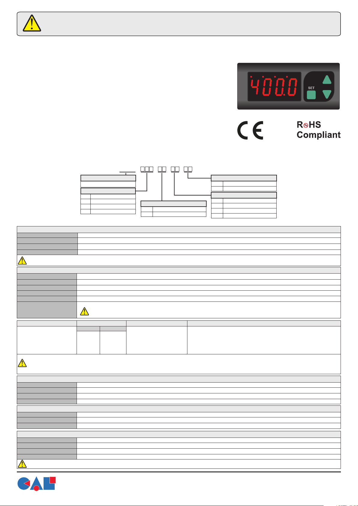
CAL EI2041 PROGRAMMABLE INDICATOR
Thank you for choosing CAL EI2041 INDICATOR.
* 35x77mm sized.
* 4 digits display.
mA
V
* Display scale can be adjusted between -1999 and 4000.
* Decimal point can be adjusted between 1st. and 3rd. digits.
* Measurement unit can be displayed.
* Selectable four different standard input types (0-20mA, 4-20mA, 0-1V, 0-10V)
* User can calibrate the device according to specified input type.
* Sampling time can be adjusted in four steps.
CAL
* Stores maximum and minimum measurement values.
* Maximum or the minimum values can be hold on the display.
* Two relay output for control and alarm. (Optional).
* Above and below setpoint value can be set.
* Selectable independent, deviation and band alarm.
* Sensor supply output. (Optional).
* RS485 Modbus RTU communication protocol feature. (Optional)
* CE marked according to European standards.
Order Code : EI2041 - - - -
Product Basic Code
Programmable Indicator
Supply Voltage Selection
230 230VAC
024 24V AC
012 12V AC
SM 9...30V DC/7...24V AC
Relay Output Selection
- n/a
2R OUT and ALARM Relay Output
Modbus Selection
- n/a
RS Modbus Communication
Sensor Supply Output
- n/a
12 12V DC 50mA
08 8V DC 50mA
05 5V DC 50mA
TECHNICAL SPECIFICATIONS
ENVIRONMENTAL CONDITIONS
Ambient/storage temperature
Max. relative humidity
Rated pollution degree
Height
Do not use the device in locations subject to corrosive and flammable gases.
ELECTRICAL CHARACTERISTICS
Supply
Power consumption
Wiring
Date retention
EMC
Safety requirements
Input type
0-1V DC voltage
0-10V DC voltage
0-20mA DC current
4-20mA DC current
While the current measuring mode, input impedance becomes 5Ω . Therefore, in current mode, the device must not be connected any voltage input.
Otherwise, the device is broken. While the device is running in the voltage measurement mode and if required to change to current measurement mode, then
firstly the voltage inputs must be removed and after that, input type must be changed to one of the current measurement modes.
0 ... +50 °C/-25 ... +70°C (with no icing).
80% Relative humidity for temperatures up to 31°C, decreasing linearly to 50% at 40°C.
According to EN 60529 Front panel : IP65 Rear panel : IP20
Max. 2000m.
230V AC +%10 -%20 or 12/24V AC ±%10 50/60Hz or 9-30V DC /7-24V AC ±%10 SMPS Optional.
Max. 7VA.
2.5mm² screw-terminal connections.
EEPROM (Min. 10 years).
EN 61326-1: 2012.
EN 61010-1: 2010 (Pollution degree 2, overvoltage category II, measurement category I).
EI2041 cannot be used if measurement category II, III or IV is required.
Measurement range
Min.
0V
0V
0mA
0mA
Max.
1.1V
12V
25mA
25mA
Measurement accuracy
±0,5% (of full scale)
±0,5% (of full scale)
±0,5% (of full scale)
±0,5% (of full scale)
Input empedance
Approx. 100kW
Approx. 100kW
Approx. 10W
Approx. 10W
ALR
OUT
EI2041
OUTPUTS
Sensor power supply
Out
Alarm
Life expectancy for relay
All sensor supply outputs maximum 50 mA. (Regulated and isolated).
Relay: 250V AC, 8A (for resistive load), NO; 1/2 HP 240V AC CosF = 0.4 (for inductive load).
Relay: 250V AC, 8A (for resistive load), NO; 1/2 HP 240V AC CosF = 0.4 (for inductive load).
Mechanical 30.000.000 operation; 100.000 operation at 250V AC, 8A resistive load.
CONTROL
Control type
Control algorithm
Hysteresis
Double set-point and alarm control.
On-Off control.
Adjustable between 1 ... 200.
HOUSING
Housing type
Dimentions
Weight
Enclosure material
While cleaning the device, solvents (thinner, benzine, acid etc.) or corrosive materials must not be used.
www.west-cs.com
|
Suitable for flush-panel mounting according to DIN 43 700.
W77xH35xD71mm.
Approx. 350g (after packaging)
Self extinguishing plastics.
WEST Control Solutions
The Hyde Business Park
Brighton East Sussex
BN2 4JU United Kingdom
Tel : +44 (0) 1273 606271
Fax : +44 (0) 1273 609990
1/5
EI2041-E-01-CAL-150520
Page 2
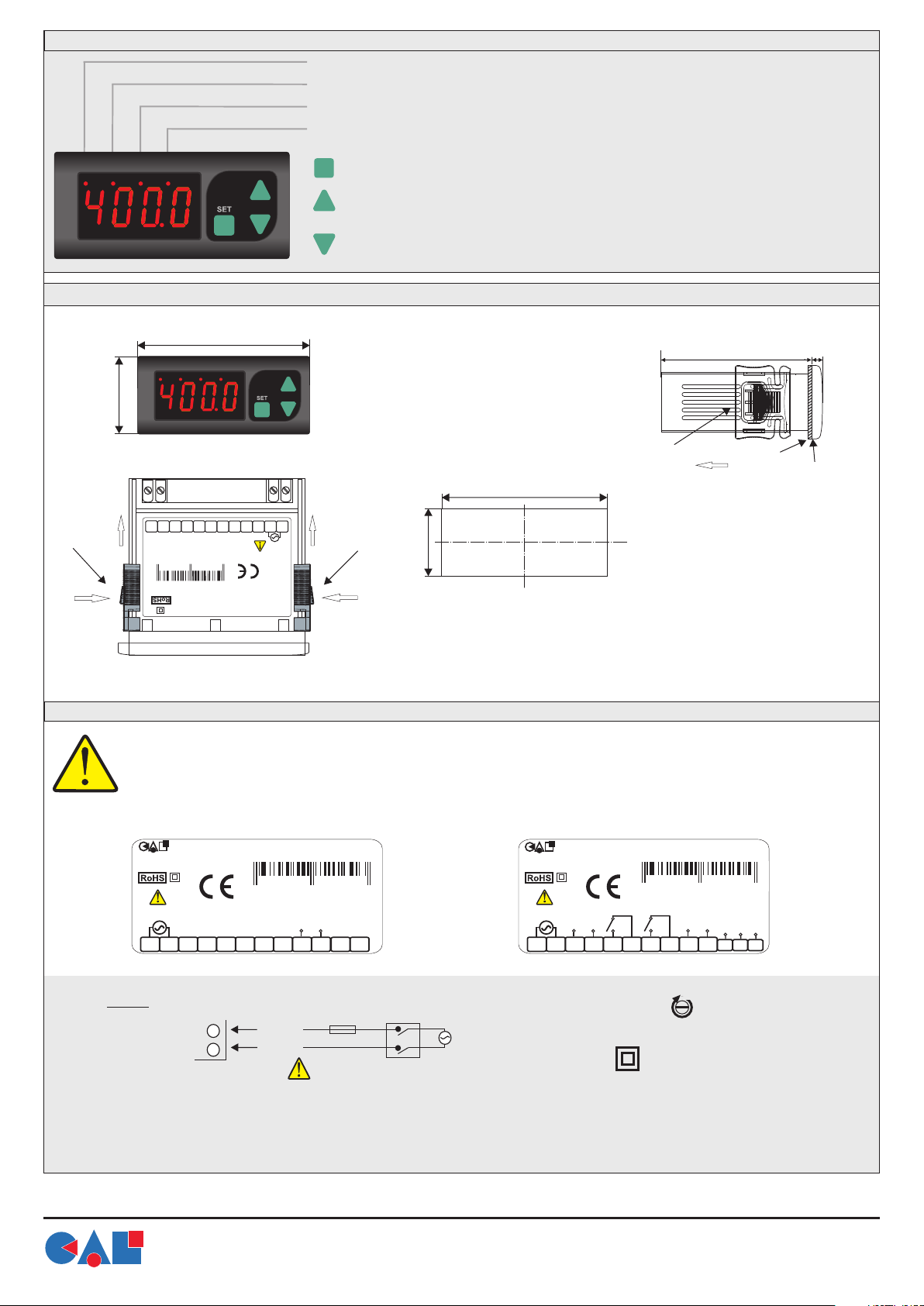
FRONT PANEL
8 680407 721603
8 680407 722204
mA
ALR
V
OUT
mA LED : If input type is selected as 0-20mA or 4-20mA, mA LED lights up.
V LED : If input type is selected as 0-1V or 0-10V, V LED lights up.
ALR LED : If alarm output is active, ALR LED lights up. During delay time, LED flashes.
OUT LED : If “OUT” is active, OUT LED lights up. During delay time, LED flashes.
SET
In "Running Mode", indicates output set value.
In “Programming Mode”, indicates the selected parameter value.
In "Running Mode", indicates the maximum measured value.
Used for incrementing values in "Programming Mode".
CAL
DIMENSIONS
35mm
Flush
mounting
clamp
2
1
mA
CAL
EI2041
77mm
OUT
ALR
V
EI2041
11 12
10
7 8 9
+
GND
INPUT
16
0
3
SN: XXXXXXXXX
8
6
8
0
4
0
7
7
2
Made In Turkey
1 2 3 4 5 6
50/60Hz 7VA
230V AC +10% - 20%
PROGRAMMABLE INDICATOR
EI2041-230
CAL INDUSTRIAL ELECTRONICS
In "Running Mode", indicates the minimum measured value.
Used for decrementing values in "Programming Mode".
For removing mounting clamps:
- Push the flush-mounting
clamp in direction 1 as
shown in the figure left.
- Then, pull out the clamp in
direction 2.
Panel cut-out
71,5mm
2
Flush
mounting
clamp
29,5mm
1
Note :
1) While panel mounting, additional distance required
for connection cables should be considered.
2) Panel thickness should be maximum 7mm.
3) If there is no 60mm free space at back side of the
device, it would be difficult to remove it from the panel.
Flush
mounting
clamp
2
Depth
71mm
5mm
Panel
Rubber packing
CONNECTION DIAGRAM
CAL EI2041 is intended for installation in control panels. Make sure that the device is used only for intended purpose. The shielding must
be grounded on the instrument side. During an installation, all of the cables that are connected to the device must be free of energy. The
device must be protected against inadmissible humidity, vibrations, severe soiling. Make sure that the operation temperature is not
exceeded. All input and output lines that are not connected to the supply network must be laid out as shielded and twisted cables. These
cables should not be close to the power cables or components. The installation and electrical connections must be carried on by a
qualified staff and must be according to the relevant locally applicable regulations.
CAL Controls | www.west-cs.com
EI2041-230
PROGRAMMABLE INDICATOR
230V AC
50/60Hz
1 2 3 4 5 6
NOTE :
SUPPLY :
184-253V AC
50/60Hz 7VA
1) Mains supply cords shall meet the requirements of IEC 60227 or IEC 60245.
Note :
2) In accordance with the safety regulations, the power supply switch shall bring the identification of the relevant instrument and it
should be easily accessible by the operator.
7 8 9
SN: XXXXXXXXX
INPUT
GND
+
10
Made in Turkey
11
12
CAL Controls | www.west-cs.com
EI2041-230-2R-05-RS
PROGRAMMABLE INDICATOR
AUX SUPPLY
GND
+
ALARM
250V 8A~
230V AC
50/60Hz
1 2 3 4 5 6
OUT
250V 8A~
7 8 9
Fuse
F 100 mA
1
2
Line
Neutral
250V AC
Fuse should
be connected
Switch
230V AC
Supply
Cable size: 1,5mm²
Equipment is protected throughout by
SN: XXXXXXXXX
Made in Turkey
INPUT
GND
+
DOUBLE INSULATION
COM
B
A
10
1
1
13
12
Holding screw
0.4-0.5Nm.
www.west-cs.com
WEST Control Solutions
The Hyde Business Park
Brighton East Sussex
BN2 4JU United Kingdom
|
Tel : +44 (0) 1273 606271
Fax : +44 (0) 1273 609990
2/5
EI2041-E-01-CAL-150520
Page 3

PROGRAMMING DEVICE
Displaying the Measurement Unit
S
S
ET
C.End
ET
&
bAr
Displaying the Maximum Measurement Unit
SE
T
Measurement
Value
RE5
1453
240
S
E
S
ET
rE5
S
ET
In "Running Mode", if key pressed for 2 seconds, maximum and minimum measurement values become
equal to the measured value at current time and the message appears on display.
Keys are locked.
Loc
&
Keys are unlocked.
unl
T
SE
T
If keys are pressed together for 2 seconds, Loc message appears and keys are
locked. For unlocking, keys are pressed together for 2 seconds, unL message
appears and keys are unlocked. If one of the keys is pressed while the device locked, Loc
1000571
In “Running Mode”, if key is pressed for 3 seconds,
maximum measurement value appears.
message appears on display.
L.INP
SE
T
5ucc
SE
T
1000571
Measurement
Value
In “Running Mode”, if keys are pressed together for 3 seconds, measurement unit appears. See Unit parameter for programming.
Displaying the Minimum Measurement Unit
1000571
In “Running Mode”, if key is pressed for 3 seconds,
minimum measurement value appears.
Measurement
Value
Resetting Maximum and Minimum Measurement Values
1000571
Measurement
Value
Locking and Unlocking
1000571
Measurement
Value
Setting Up User Calibration Values
if the standard input values (0-20mA, 4-20mA, 0-1V, 0-10V) will be used, calibration will not be necessary. Except these input values, if different input values to be used Cal.t
parameter must be selected as U.Inp .
In user menu, if key is pressed for 7 seconds, message appears on display and calibration menu is entered.
Voltage or current which are corresponds to L5Cl parameter is applied to device input and key is pressed. If operation is success, message appears on
display and proceeding to the next step.
In this step, while message displayed, voltage or current which are corresponds to L5Cl parameter is applied to device input and key is pressed. If operation is
success, then message appears on display, calibration process is completed and the device will start running according to the new calibration values.
H.inp
5ucc
ERROR MESSAGES & DESCRIPTIONS
Error conditions and descriptions are listed below.
* If voltage or current is difference and lower than half of full scale between H.inP and L.inP voltage or current.
* If excessive high-low input current or voltage is applied.
* If an error occurs during L.inP calibration, Err1 message appears on display.
* If an error occurs during H.inP calibration, Err2 and C.Err message appears on display.
* If user calibration is not applied before and an error occurs during calibration process, device runs according to standard calibration values.
* If user calibration is applied before and an error occurs during calibration process, device runs according to previous user calibration values.
Changing Parameters
If keys are pressed together for 2 seconds, Pi message appears and user menu entered. Then in user menu, first parameter's is displayed.
&
When a parameter selected, if key is pressed selected parameter value appears and displayed parameter can be changed by keys. If no
operation is performed for 3 seconds after the parameter value is being displayed or key is pressed, parameter name will be shown again. While
parameter name displayed, keys are pressed together, returned to "Running Mode" without waiting period.
Hidden Menu
If key is for 7 seconds P2 message appears on the display and hidden menu is entered. Selected
pressed
parameter values can be displayed with key and canged with keys. Accessing to the parameters and
storing functions are as in the user menu. All parameters can be accessed from this menu.
Parameter Transfer Between Menus
SE
I.typ
baUd
T
If keys are pressed together for 2 seconds, parameter transferred to user menu. In this way up to 12
parameters can be transferred to the user menu.
In user menu, if keys are pressed together for 2 seconds, parameter is removed from user menu. When a
S
ET
parameter is displayed in the user menu, mA LED lights up in the hidden menu.
Setting Up ParametersMeasurement Unit (Unit)
If pressed key in Unit parameter, related digit blinks on display. For desired number, letter or symbol is adjusted by pressing the key for related digit. For
SET
setting up other digits key is pressed. When parameter setting process is completed, by pressing key or no key is pressed for 3 seconds without pressing any
key, parameters can be saved.
Factory Defaults
Key is held down while the device is powered up,
message will see and restore the factory parameters
Running Mode Error Messages
S
E
T
S
ET
Programming Mode
SE
T
I.typ
C.Fos
C.FosBaud
S
ET
Viewing the Revision
S
E
d.Par
In “Running Mode”, if keys are together pressed for 3 seconds,
r.001
revision information appears on display.
T
&
&
Input voltage or input
www.west-cs.com
L.inp.
current below zero.
|
WEST Control Solutions
The Hyde Business Park
Brighton East Sussex
BN2 4JU United Kingdom
Tel : +44 (0) 1273 606271
Fax : +44 (0) 1273 609990
H.inp.
Input voltage higher then 15V
input current higher than 25mA.
or
Err.1
L.INP calibration
error
3/5
Err.2
H.INP calibration
error
C.Err
Calibration failed
EI2041-E-01-CAL-150520
Page 4

Independent alarm
A.tyP.=indE
ON
OFF
A.5tA.= Hi
Deviation alarm
A.tyP.= dE.
O.5Et
ALARM CONDITIONS
ON
A.5tA.= Hi
OFF
Band alarm
A.tyP.= bAnd
O.5Et
ON
OFF
A.5tA.= Bo.Hi.
O.5Et: Out set value
A.5Et: Alarm set value
ON
A.5tA.= Lo
OFF
A.Hy5
A.5Et
CONFIGURATION PARAMETERS
I.typ
d5p.C
ratE
Hold
Unit
Cal.t
d.Pnt
L.5CL
H.5CL
Input type selection. (0-20mA, 4-20 0-1 0-10 )mA, V, V
Indicator configuration. (prc5 : Process value, Pr.Un : 4 Seconds process value, 2 Seconds Unit value.)
Measurement ranges.
Fa5t : Average of 1 measurement value is gathered in 200msec.
5lo.1 : Average of 4 measurement value is gathered in 200msec.
5lo2 : Average of 8 measurement value is gathered in 200msec.
5lo3 : Average of 16 measurement value is gathered in 200msec.
Indicator holding parameter. ( nonE : instant measurement value, lo. : minimum value, HI : maximum value is displayed.)
Measurement value. (Desired measurement value for unit selection).
Calibration type. ( 5.Inp : Standard input type, U.Inp : User defined input type selection ).
Decimal point selection. ( Adjustable between the 1th. and 3rd digits ).
Lower scale value. ( Adjustable between -1999 and H.5CL value ).
Upper scale value. ( Adjustable between L.5CL and 4000 value ).
OUTPUT CONTROL PARAMETERS
O.5Et
O.HY5
O.5ta
O.Pon
O.ton
O.toF
Output set value. ( Adjustable between L.5CL and H.5CL).
Output hysteresis value. ( Adjustable between 1 and 200 ).
Output status. (Off: Output not active, Lo: Becomes active below the setpoint output value, H1:Becomes active above the setpoint output value).
Required relay-on delay time in order to set output to active state after power-up. ( Adjustable between 0 and 99 minutes ).
Output relay-on delay time. ( Adjustable between 0 and 99 minutes ).
Output relay-off delay time. Adjustable between 0 and 99 minutes ).(
ALARM CONTROL PARAMETERS
a.5Et
a.HY5
a.typ
a.5ta
A.Pon
A.ton
A.toF
Alarm set value. ( L.5CL and H.5CL).Adjustable between
Alarm hysteresis value. ( 1 and 200 ).Adjustable between
Alarm type. (IndE : Independent alarm, dE: Deviation alarm, band: Band alarm)
Alarm condition. (OFF:Alarm not active. For independent or deviation alarm, H1: Alarm is active
above the set value. For band alarm, BI.HI : Activated in "in-band", Bo.HI : Activated in "out-band".)
Required relay-on delay time in order to set alarm output to active state after power-up. ( Adjustable between 0 and 99 minutes ).
Alarm output relay-on delay time. ( Adjustable between 0 and 99 minutes ).
Alarm output relay-off delay time. Adjustable between 0 and 99 minutes ).(
RS485 MODBUS COMMUNICATION PARAMETERS
adr5
baUd
Slave device address. ( Adjustable between 1 and 247 )
Baudrate. ( Off, 1200, 2400, 4800, 9600,19200 kbps ayarlanabilir )
A.Hy5
O.5Et + A.5Et
ON
OFF
A.5tA.= Lo
PARAMETER LIST
Lo: Alarm is active below the set value,
A.Hy5
O.5Et - A.5Et
A.Hy5
O.5Et + A.5Et
ON
OFF
A.5tA.= Bi.Hi.
Initial Value
0-10
Prc5
5lo.1
nonE
nonE
5.Inp
0
0
2000
Initial Value
2000
2
oFF
01:00
01:00
01:00
Initial Value
2000
2
indE
oFF
01:00
01:00
01:00
Initial Value
1
9600
www.west-cs.com
WEST Control Solutions
The Hyde Business Park
Brighton East Sussex
BN2 4JU United Kingdom
|
Tel : +44 (0) 1273 606271
Fax : +44 (0) 1273 609990
4/5
EI2041-E-01-CAL-150520
Page 5

MODBUS ADDRESS MAP
HOLDING REGISTERS
Holding Register
Addresses
Decimal
0000d 0x0000 word R Wi.tyP
0001d 0x0001 word
0002d 0x0002 word
0003d 0x0003 word
0004d 0x0004 word
0005d 0x0005 word
0006d 0x0006 word
0007d 0x0007 word
0008d 0x0008 word
0009d 0x0009 word
0010d 0x000A word
0011d 0x000B word
0012d 0x000C word
0013d 0x000D word
0014d 0x000E word
0015d 0x000F word
0016d 0x0010 word
0017d 0x0011 word
0018d 0x0012 word
Hex
Data
Type
Input type selection. 0=0-20;1=4-20;2=0-1;3=0-10
Measurement ranges. 0=Fa5t;1=5.lo1;2=5.lo2;3=5.lo3
Indicator locking parameter. 0=nonE;1=lo;2=HI
Decimal point. 0=x;1=x.x;2=x.xx;3=x.xxx
Scale lower value.
Scale upper value.
Output set value.
Output hysteresis value.
Output condition. (0=OFF,1=Lo, 2=H1)
Required relay-on delay time in order to set output to active state after power-up.
Output relay-on delay time.
Output relay-off delay time.
Alarm set value.
Alarm hysteresis value.
Alarm type. 0=IndE;1=dE;2=band
Alarm condition. 0=OFF, 1=Lo;1=H1;2=b1.H1;3=bo.H1
Required relay-on delay time in order to set alarm output to active state after power-up.
Alarm output relay-on delay time.
Alarm output relay-off delay time.
Data Content
Parameter
Name
RAtE
hold
d.pnt
l.5Cl
H.5Cl
o.5Et
o.Hy5
o.5ta
o.pon
o.ton
o.tof
a.5Et
a.HY5
A.typ
A.5ta
a.pon
a.ton
a.tof
INPUT REGISTERS
Holding Register
Addresses
Decimal
0000d 0x0000 word Read Only–
0001d 0x0001 word
0002d 0x0002 word
* Holding and Input Register parameters, which in integer type is defined as signed integer. Timing parameters are defined as seconds.
(For example, 01:15 is defined as 75 seconds).
Hex
Data
Type
Measured value
Minimum measured value
Maximum measured value
Data Content
Parameter
Name
–
–
DISCRATE INPUTS
Holding Register
Addresses
Decimal
0000d 0x0000 bit Read Only–
0001d 0x0001 bit –
Hex
Data
Type
OUT Control output condition. (0=OFF; 1=ON).
Alarm control output condition. (0=OFF; 1=ON).
Data Content
Parameter
Name
COILS
Coil
Addresses
Decimal
0000d 0x0000 bit R Wd5p.C
0001d 0x0001 bit Cal.t
Hex
Data
Type
Indicator configuration oFF=pr.C5, ON=Pr.Un
Calibration type oFF=5.Inp, ON=U.Inp
Data Content
Parameter
Name
Read / Write
Permission
R W
R W
R W
R W
R W
R W
R W
R W
R W
R W
R W
R W
R W
R W
R W
R W
R W
R W
Read / Write
Permission
Read Only
Read Only
Read / Write
Permission
Read Only
Read / Write
Permission
R W
www.west-cs.com
WEST Control Solutions
The Hyde Business Park
Brighton East Sussex
BN2 4JU United Kingdom
|
Tel : +44 (0) 1273 606271
Fax : +44 (0) 1273 609990
5/5
EI2041-E-01-CAL-150520
 Loading...