

Page 1
CALogix installation sheet Page 1 of 6
System Overview
CALogix is a modular multi-loop PID controller with logic function capability. The controller consists of a
DIN-rail mount base-unit that incorporates power supply, RS485 communications ports and slots for up
to 4 control modules. The control modules are available as PID or Logic I/O and can be selected then
mounted into the base-unit as required for the application. Variations in PID control modules include
temperature sensor and linear (0-50mV, 4-20mA, 0-5V & 0-10V) inputs with options for relay, ssd or
analog (4-20mA, 0-5V & 0-10V) outputs. Logic I/O modules have user defined 0-5, 0-10, 0-24Vdc inputs
with relay or ssd outputs. All wiring connectors to the base uni t and control modules are plug-in to
reduce installation and maintenance times.
CALogix is configured using the Windows based CALogix-sw configuration tool which is provided with
each base-unit. PID setup, input & output parameter settings, profile creation and writing logic function
block diagrams can all be performed within the software utility. These settings can be read, modified and
written to and from the controller and also saved on the PC as a file to be recalled at a later date when
required. The program also provides information on current process value, set-points and output status
which can be useful when commissioning the system.
Mechanical Installation
The controller is designed as two main components
BASE-UNIT
DIN rail mount device containing main CPU and connections for up to 4 control modules.
CONTROL MODULE
PID or Logic control modules can be mixed as required for the application and plugged in to base-unit.
1 base-unit and 1-4 control modules must be used for operation of product. A CALogix system can
only be configured using CALogix-sw pc -based software.
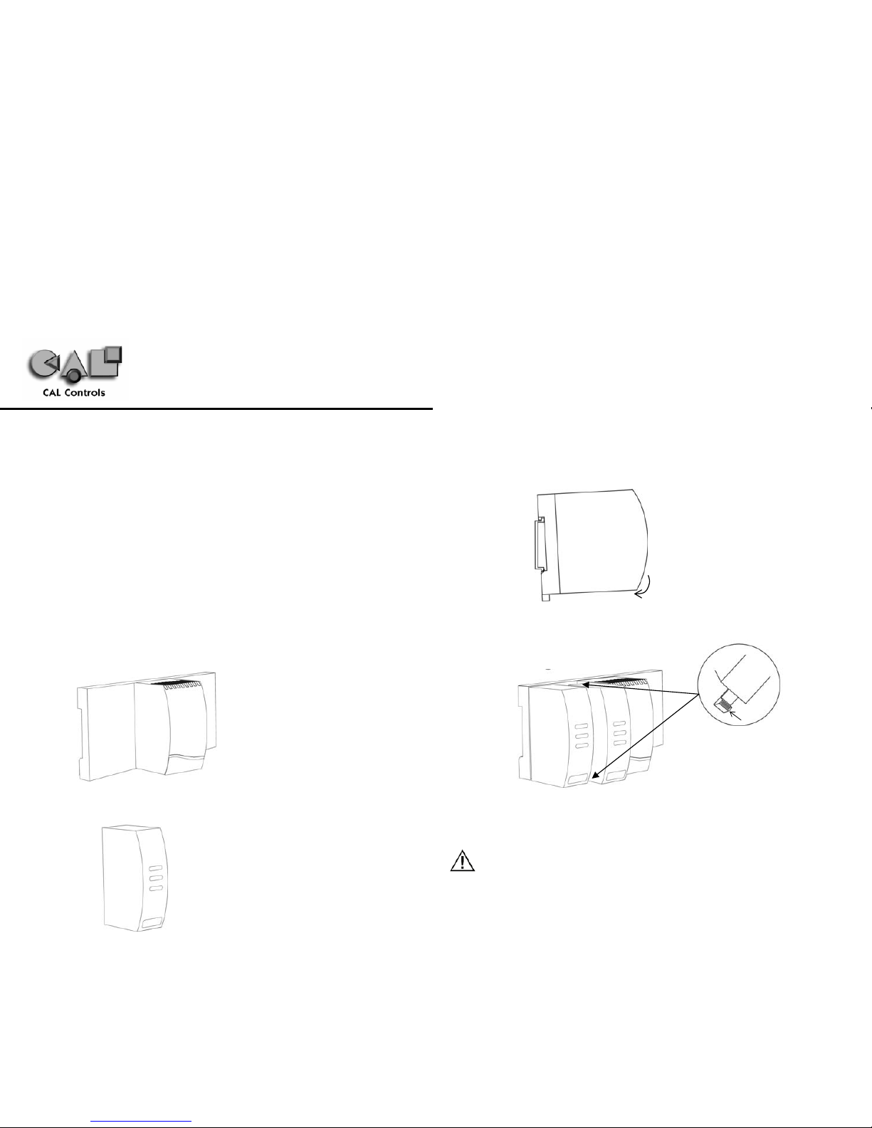
MOUNTING
To mount a base unit with control modules proceed as follows:
1. Affix 35mm type DIN rail securely to mounting surface, minimum length 140mm. The unit
should be mounted vertically as shown.
2. Attach carrier unit to DIN rail ensuring the spring release is at the bottom, facing downward.
3. Ensuring the input terminals are facing downwards, add the control modules to base unit.
Press the top and bottom tabs on the module lightly and ensuring module is kept straight,
push to locate in base unit (see diagram below).
4. Pre-wire connectors and plug into the appropriate modules (we suggest wire ma rkers for
identification)
REMOVING A MODULE
1. Isolate supply to CALogix and all module input and output connectors.
2. Unplug connectors to module requiring removal.
3. Press tabs as shown above to release module.
4. Carefully pull the module away from base-unit ensuring tabs are free to remove.
Press
CALogix Installation Instructions
DM0000M20
Page 2

CALogix installation sheet Page 2 of 6
REMOVING BASE-UNIT FROM DIN-RAIL
1. Isolate supply to CALogix and all module input and output connectors.
2. Unplug connectors to base-unit and all modules.
3. Insert screwdriver into DIN-rail release block and apply pressure away from the controller, the
base-unit can then be removed.
REPLACING A CONTROL MODULE
When replacing a control module follow the instructions above for removing and installing control
modules. If a control module is being replaced with another that has the same part number, all
parameter settings will be automatically transferred from the base unit to the new module on repowering the system, no reconfiguration will be required.
If a module is being replaced with a module that has a different part number, ensure
that the system is re-wired accordingly and the module settings are modified to reflect the
changes made, before running your system. Failure to do so may result in dangerous operation
or damage to the system.
If you are replacing logic modules with PID modules, it is important to turn off or delete any
associated logic.
CLEANING
Wipe down with damp cloth (water only).
DIMENSIONS
Electrical Installation
The system is designed to be installed in an enclosure which provides adequate protection against
electrical shock. The enclosure should also be of a sufficient IP (NEMA) rating for protection against
water and dust.
OUTPUT DEVICES
Three types of output are available on a module: relay, solid state relay drive (ssd) and analog. Output
1 may be any one of the three options, output 2 can be relay or ssd and output 3 is always relay. Any
of these outputs can be assigned as SP1, SP2 and SP3 using the CALogix-sw software. Check the
model number and output configuration before wiring the instrument and applying power. See section
on output options for more details.
1. Solid state relay drive
12Vdc +10/-15% (nominal), 20mA
To switch remote SSR
2. Miniature power relay
2A/250Vac resistive, Form A/SPST contacts
3. Analog Output (Isolated) - NOT AVAILABLE WITH LOGIC I/O MODULE
Specify 4-20mA 500Ω max, ±0.1% fs typical
0-5Vdc 10mA (500Ω min). ±0.1% fs typical
0-10Vdc 10mA (1KΩ min). ±0.1% fs typical
SUPPLY VOLTAGE
18-30Vdc, 8 watts ±10% fluctuation permitted
WIRING THE CONNEC TOR
Prepare the cable carefully, remove between 6 and 8mm insulation and ideally tin or terminate to avoid
bridging. Prevent excessive cable strain. Maximum recommended wire size 32/0.2mm 1.0mm² (18
AWG)
REPLACING MODULES
Hot-plugging of modules should not be carried out. To change a module always de-power the baseunit. Once power is re-applied the carrier will reload the settings for that module and continue with the
original module settings. Hot-plugging can cause the carrier to fail and is potentially dangerous.
INDUCTIVE LOADS
To prolong relay contact life and suppress interference, it is recommended engineering practice to fit a
snubber (0.1µF/100Ω) between relay output terminals.
EN61010 - 1 / UL61010C-1/ CSA22.2 No 1010
Compliance shall not be impaired when fitted to the final installation.
Designed to offer a minimum of basic insulation only.
− The body responsible for the installation is to ensure suitable for measurement category II or III
− To avoid possible hazards, accessible co nductive parts of the installation shou ld be protectively
earthed in accordance with EN61010 for Class 1 equipment.
CAUTION
Snubber leakage current can cause some electro-mechanical devices to be held ON. Check
with manufacturers specification.
Note : Ensure adequate clearance for connectors and wiring
Page 3

CALogix installation sheet Page 3 of 6
− Output wiring should be within a protectively earthed cabinet.
− Sensor sheaths should be bonded to protective earth or not be accessible
− Live parts should not be accessible without the use of a tool.
EMC GUIDELINES
We make a number of general recommendations that can reduce the possibility of EMC problems.
1) It is important to suppress CALogix relay contacts, this will reduce switching interference and
also prolongs life of the contacts.
RC Networks fitted across the relay contacts are recommended for resistive and larger
inductive loads, values such as 0.1µF capacitor in series with a 100Ω resistor.
For small inductive loads, a suitable rated VDR is recommended.
For small inductive dc loads, relays etc, a suitably rated diode fitted in parallel with the load is
recommended.
2) CALogix should be mounted into a metal cabinet which is properly earthed, good all round
metal shielding is important.
3) It should be borne in mind that the wiring of the installation can significantly reduce the
efficiency of the instrumentation immunity. This is due to the ease with which high frequency
RF can enter via unprotected incoming and outgoing cables.
Earthed thermocouples or sensors with screened cable, should be earthed at the cabinet
entry point.
Any long cables entering the control cabine t should be protected at the point where they
enter the cabinet, large diameter ferrite sleeves are an economical and effective method of
reducing high frequency RF, looping the cables through ferrite sleeves a number of times
will improve the efficiency of the filtering.
Alternatively for mains cables, the fitting of a suitable mains filter can provide goo d results.
Data or communications cables should be screened. If using Belden 8132 connect drain
wire to PIN 5 of a shielded RJ45 connector.
Ideally data and sensor cables should be routed separately from power cables and away
from inverters or other high power/frequency devices.
SUPPLY AND RS485 COMMUNICATIONS CONNECTIONS
INPUT OPTIONS
7P---0A000 7P---0A000 7P---0A000
7P---0B000 = 4-20mA
7P---0C000 = 0-5V
7P---0D000 = 0-10V
7L---0E000
Page 4

CALogix installation sheet Page 4 of 6
OUTPUT OPTIONS
EXAMPLE CIRCUIT
The circuit below shows an example applicaion which includes a base-unit that has one PID module and
one logic module fitted.
It is strongly recommended that the power supply zero volts and all logic module zero volts are
common to prevent ground loops.
INPUT SENSOR SELECTION
* Note : Type-B accuracy not specified below 100°C/212°F
Configuring and Networking CALogix
CALogix is configured using Windows-based CALogix-sw software. Before using CALogix–sw,
connect CALogix to a PC as shown below:
CALOGIX NETWORK
CALogix uses RS485 full duplex serial communications link which is the standard most common ly
used for industrial applications due to high noise immunity and multi-drop capability. It enables a PC to
communicate with up to 31 CALogix base-units over distances up to 1200 metres, and requi res the
addition of an RS485 interface card, o r a separate RS232 / 485 converter connected to the RS232 port
of the PC. RS485 converters that derive power from the RS232 port must have all 9 pins (RS232)
connected for full operation of the converter.
RS485 cards and converters can differ greatly in their requirements and therefore the installation
instructions supplied with the interface should be read carefully.
2m CALogix-PC cable (part number - CAB RJ45 2M 01) and a RS232/485 converter (part number 3C 25 000 K 3X) that fits directly on to the RS23 2 serial port on a PC are available from your nearest
CAL Controls distributor.
Thermocouple type Description Sensor Range (°C) Sensor Range (°F)
B Pt-30% Rh/Pt-6% Rh 0 to1800°C* 32 to 3272°F*
E Chromel/Con 0 to 600°C 32 to 1112°F
J Iron/Constantan 0 to 800°C 32 to 1472°F
K Chromel/Alumel -50 to 1200°C -58 t o 2192°F
L Fe/Konst 0 to 800°C 32 to 1472°F
N Nicrosil/NiSil -50 to 1200°C -58 to 2192°F
R Pt-13%Rh/Pt 0 to 1600°C 32 to 2192°F
S Pt10%Rh/Pt 0 to 1600°C 32 to 2192°F
T Copp er/Con -200 to 250°C -273 to 48 2°F
Resistance Thermometer
rtd 2/3 wire
Pt100/RTD-2/3 -200 to 800°C -273 to 1472°F
7P111----7L111-----
7P211----7L211-----
7P221----7L221-----
7PB11----- = 4-20mA
7PC11----- = 0-5V
7PD11----- = 0-10V
7PB21
= 4-20mA
7PC21 = 0-5V
7PD21 = 0-10V
FS1 Fuse = 1A time lag type to IEC127. CSA/UL rating 250V
FS2 Fuse = 2A time lag type to IEC127. CSA/UL rating 250V
FS3 Fuse = High rupture capacity (HRC). Suitable for maximum rated load current
S1 switch = IEC/CSA/UL approved disconnection device must be used
<15m <1200m
RS232/485 converter
RS485 from PC
To other
CALogix
controllers
Page 5

CALogix installation sheet Page 5 of 6
If wiring your own cable the RS485 connections are as follows.
As CALogix is designed for an industrial environment, CAL recommends using a 4 wire shielded RS485
cable such as Belden 8132. Ensure that connectors are suitable for use with shielded cable and are
correctly bonded.
Auto-baud rate function. On power up CALogix detects the network speed and automatically adjusts
its baud rate accordingly. If the network baud rate is later modified, remove the power and reapply so
that CALogix can resynchronise to the new baud rate.
MULTIPLE CALOGIX NETWORKS
Each CALogix unit has an RS485-in and RS485-out RJ45 socket. To connect a number of CALogix
units on a network, wire as shown below. The cables should be wired so that the corresponding pins of
RS485-out are connected to the same pin number on RS485-in of the next controller i.e. Pin 2 (out) to
Pin 2 (in), Pin 3 (out) to Pin 3(in), Pin 5(out) to Pin 5(in), Pin 6(out) to Pin 6(in) and Pin 7(out) to
Pin 7(in).
For multiple instrument networks each transmission line must be properly terminated to prevent
reflections. 120Ω termination resistors should be fitted between TX+ & TX- and RX+ & RX- at the
connection to the PC in addition to the last instrument in the chain. See example below.
When transmission lines are not transmitting, they remain in an intermediate state which can allow
receivers to receive invalid data bits due to electrical noise on the cable. To prevent this bias resistors
may be required to force the lines into a known state. Some RS485 interface cards and converters
may have bias resistors fitted please check manufacturer’s specification and recommendations for use
of bias resistors.
Note: The default Modbus address for each base-unit is 1, for a network with a number of CALogix
units, power-up each unit individually and configure them with a unique Modbus address using
CALogix-sw configuration tool. (See section on base-unit set-up in programming manual on cd)
CALOGIX-SW MINIMUM PC SYSTEM REQUIREMENTS
As a general requirement, we would recommend a minimum of Pentium 450MHz with 256MB RAM,
Windows
TM
2000/XP and screen resolution, 1024 x 768.
INSTALLING CALOGIX-SW
1. Insert CALogix-sw disk into CD-drive.
2. CALogix-sw install program should auto-run. If this does not happen, manually run
‘setup.exe’ on CALogix-sw cd.
3. Follow on screen instructions to complete installation.
RUNNING CALOGIX-SW
1. Click ‘start’ on Windows toolbar.
2. Mouse-over ‘all programs’.
3. Mouse-over ‘CALogix folder’ in menu.
4. Click on ‘CALogix’ icon.
5. CALogix program should now run.
USING CALOGIX-SW
1. Refer to on-screen help or CALogix programming manual contained on CALogix-sw CD.
DIAGNOSTICS
Each control module has LEDs to indicate when each of the outputs are on
(or relay closed). If an analogue output option is fitted the LED dims
proportionately with the output level, e.g. a PID module with a 4-20mA output,
the LED will be dim at 4mA and bright at 20mA.
Note: The output and the LED indicator are physically linked and always
represent the true state
of the output.
CALogix base-unit has three status LED’s to assist with diagnosing problems
RJ45 PIN
2 RX+
3 RX 4 / 5 GND
6 TX 7 TX+
LED 1 – Communications
Off No communications
On/Pulsing Communications active
LED 2 – CALogix healthy (Heartbeat)
Slow pulse Unit operating correctly
Fast Pulse Base-unit emergency (comms still running)
On Base-unit lock-up
When base-unit emergency/lock-up conditions exist recycle power to clear. If the
problem is not clear on power recycle contact CAL controls for technical support.
LED 3 – Logic
Off Logic not active
On Logic active
To start logic program running refer to section on running logic programs
Page 6

CALogix installation sheet Page 6 of 6
Specification
PID MODULE :
THERMOCOUPLE – 9 Types – B, E, J, K, L, N, R, S, T
Standards IEC 584-1
CJC rejection 30:1 typical
External resistance 100Ω maximum
RESISTANCE THERMOMETER – 2 or 3 Wire
Standards IEC 751
(100Ω 0°/138.5Ω 100°C Pt)
Bulb Current 0.2mA maximum
LINEAR PROCESS INPUTS
Linear Input Typical Accuracy Range
0-50mV ±0.1% ± 0.00 – 99.99, ±100.00 – 499.95,
±500 – 999.9, ±1000 – 9999
4-20mA ±0.1% As above
0-5V ±0.1% As above
0-10V ±0.1% As above
APPLICABLE TO ALL INPUTS (SM = Sensor maximum, FS=Full scale)
Calibration Accuracy ±0.1% FS typical ±1°C
Sampling Frequency Input 10Hz, CJC 4sec
Common mode rejection Negligible effect up to 140dB, 240V, 50-60Hz
Temperature coefficient 50ppm/°C SM typical
OUTPUT DEVICES
Solid state relay driver : SSd1 and SSd2 12Vdc +10/-15% 20mA
Miniature power relay: Rly1, Rly2, Rly3 2A/250ac resistive load, form A/SPST
Analogue Output 4-20mA 500Ω max ±0.1% FS typical
0-5Vdc 10mA 500Ω min ±0.1% FS typical
0-10Vdc 10mA 1KΩ min ±0.1% FS typical
LOGIC I/O MODULE :
Input Range 0-5 / 0-10 / 0-24 Vdc (s/w select)
Outputs SSd1 and SSd2
Rly1, Rly2, Rly3
12Vdc +10/-15% 20mA
2A/250ac resistive load, form A/SPST
Maximum counter input frequency 1 fast 1KHz, Other 10Hz
Accuracy ±1%
ENVIRONMENTAL:
Safety EN61010,
UL and CSA approvals pending
Measurement Categories II and III
Pollution Degree II
EMC Emission EN61000-6-3
EMC Immunity EN61000-6-2
Mouldings Flame retardant polycarbonate
Weight
(including connectors)
Base unit – 170g, 6oz
Control module – 90g, 3.2 oz
Ambient* 0 to 55°C
Humidity 90% max non-condensing
Altitude Up to 2000m
SUPPLY:
Supply voltage 18-30Vdc, 8 watts ±10% fluctuation permitted
*
Note : As with all electronic devices, product life is reduced at high ambient temperatures.
Ensure that your control panel sufficiently cooled to maximise product life.
Safety and Warranty Information
Installation
EN6110-1 / UL61010C-1 / CSA 22.2 No 1010
To offer a minimum of basic insulation only
Suitable for measurement within category II and III and pollution degree 2
See Electrical installation
It is the responsibility of the installing engineer to ensure this equipment is installed as specified in this
manual and is in compliance with appropriate wiring regulations.
Configuration
The controller can only be configured using CALogix-sw or CALgrafix software. It is the responsibility
of the installing engineer to ensure that the configuration is safe.
Ultimate Safety Alarms
Do not use SP2/SP3 or logic module outputs as the sole alarm where personal injury or damage may
be caused by equipment failure.
Warranty
CAL Controls warrant this product free from defect in workmanship and materials for three (3) years
from data of purchase.
1. Should the unit malfunction, return it to the factory. If defective it will be repaired or replaced
at no charge.
2. There are no user serviceable parts in this unit. The warranty is void if the unit shows
evidence of being tampered with or subjected to excessive heat, moisture, corrosion or
other misuse.
3. Components which wear or damage with mis use are excluded e.g. relays.
4. CAL Controls shall not be responsible for any damage or losses however caused, which
may be experienced as a result of the installation or use of this product.
CAL Controls liability for any breach of this agreement shall not exceed the purchase price paid.
E & O.E.
CAL Controls Ltd
Bury Mead Road, Hitchin,
Herts, SG5 1RT, UK
Tel +44 (0) 1462 436161
Fax +44 (0) 1462 451801
e-mail sales@cal-controls.co.uk
www.cal-controls.com
CAL Controls Inc
1117 S. Milwaukee Av,
Libertyville, IL60048, USA
Tel (847) 680-7080
Fax (847) 816-6852
e-mail sales@cal-controls.com
www.cal-controls.com
33086/01/0104
 Loading...