

Calcana PH Series, PH-40, PH-50, PH-75, PH-75 HO Specifications, Installation, Operation Service And Spare Parts Manual
...
PH-SERIES Specifications, Installation, Operation Service and Spare Parts Manual
Printed in USA © 2019 Calcana USA Ltd. Rev 5 1/19
Gas Fired Outdoor Infrared Patio Heater/Gas-Fired Infrared Patio Heater
Vented Radiant Tube Heater/ L’Appareil de chauffage de Tube Rayonnant donné vent
Gravity Vented Wall Furnace/ La gravité A Donné vent Fournaise de Mur
MODELS PH40, 50, 75, 80, 100 and 125 ONLY: For either indoor or outdoor installation/Installer à l’intérieur
ou à l’extérieur
For Industrial, Commercial, and Residential Patio and Restaurant Applications.
WARNING: Improper installation, adjustment,
alteration, service or maintenance can cause
property damage, injury or death. Read (refer to)
the installation operating and maintenance
instructions thoroughly before installing or
servicing this equipment. For assistance or
additional information consult a qualified installer,
service agency or the gas supplier.
ADVERTISSEMENT. L’installation déplacée,
l’ajustement, le changement, le service ou
l’entretien peuvent causer les dommages de
propriété, la blessure ou la mort. Lire (se référer à)
l’installation qui fonctionne et les instructions
d’entretien à fond avant d’installer ou entretenir
cet équipement. Pour obtenir de l’aide ou les
informations supplémentaires consultent un
programme d’installation, une agence de service
ou le fournisseur de gaz qualifié.
WARNING: If the information in these instructions
is not followed exactly, a fire or explosion may result;
causing property damage, personal injury or loss of
life.
ADVERTISSEMENT: Assurez-vous de bien
suivre les instructions données dans cette notice
pour réduire au minimum le risqué d’incendie ou
d’explosion ou pour éviter tout dommage
matériel, toute blessure ou la mort.
-Do not store or use gasoline or other flammable vapors
and liquids in the vicinity of this or any other appliance.
- WHAT TO DO IF YOU SMELL GAS:
1) Extinguish any open flame
2) DO NOT try to light any appliance.
3) DO NOT use or touch any electrical switches.
4) DO NOT use any phone in your building
5) Turn off gas.
6) Open Windows
7) Leave the building
8) Immediately call your gas supplier from a
neighbor’s phone or after you have left the
building. Follow the gas supplier's instructions.
9) If you cannot reach your gas supplier, call the fire
department.
- Installation and service must be performed by a
qualified installer, service agency or the gas supplier
- Ne pas entreposer ni utiliser d’essence ni d’autres
vapours ou liquidés inflammables à proximité de cet
appareil ou de tout autre appareil.
- QUE FAIRE SI VOUV SENTEZ UNE ODEUR DE GAZ:
1) Éteindre la flamme ouverte
2) Ne pas tenter d’allumer d’appareils
3) Ne touchez à aucun interrupteur.
4) Ne pas vous server des téléphonés dans le
bâtiment ou vous vous trouvez.
5) le Virage du gaz.
6) Ouvrir Windows
7) Part le bâtiment
8) Appelez immédiatement votre fournisseur de
gaz depuis un voisin ou âpres que vous êtes
parti le bâtiment. Suivez les instructions du
fournisseur.
9) Si vous ne pouvez rejoindre le service des
incendies.
- L’installation et I' entretien doivent être assures par
un installateur ou un service d’entretien qualifié ou
par fournisseur de gaz.
WARNING: Heat exchanger surface is hot. Do not touch surface or burn may result. Combustible material or articles should
not be placed on or near heater. Observe clearance to combustibles as noted on heater and in this manual.
INSTALLER: Leave this manual with the
appliance.
CONSUMER: Retain this manual for future
reference.
INSATLLATEUR: Laissez cette notice
avec I’ appareil.
CONSOMMATEUR: Conservez cette
notice pour consultation ultérieure.
Calcana USA Ltd.
30201 Country Road 49
Loxley, AL, 36551
Tel: 251-964-4400
Fax: 251-964-4404
WARNING: MODELS PH-40HO, PH-75HO, PH-80,
PH-100HO, PH-125HO Are For Outdoor Use Only

PH-SERIES
ii
WHEN AN EXISTING CATEGORY I HEATER IS REMOVED OR
REPLACED, THE ORGINAL VENTING SYSTEM MAY NO LONGER
BE SIZED TO PROPERLY VENT THE ATTACHED APPLIANCES.
The effects of an improperly sized venting system can
include but not limited to: the formation of
condensate, leakage, spillage etc. The following test
procedure is required:
WARNING
CARBON MONOXIDE POISONING HAZARD
Failure to follow the steps outlined below for each appliance connected
to the venting system being placed into operation could result in carbon
monoxide poisoning or death.
The following steps shall be followed for each appliance connected to
the venting system being placed into operation, while all other
appliances connected to the venting system are not in operation:
1) Seal any unused openings in the venting system.
2) Inspect the venting system for proper size and horizontal pitch, as
required in the National Fuel Gas Code, ANSI Z223.1/NFPA 54 or the
Natural Gas and Propane Installation Code, CSA B149.1 and these
instructions. Determine that there is no blockage or restriction,
leakage, corrosion and other deficiencies which could cause an
unsafe condition.
3) As far as practical, close all building doors and windows and all
doors between the space in which the appliance(s) connected to
the venting system are located and other spaces of the building.
4) Close fireplace dampers.
5) Turn on clothes dryers and any appliance not connected to the
venting system. Turn on any exhaust fans, such as range hoods and
bathroom exhausts, so they are operating at maximum speed. Do
not operate a summer exhaust fan.
6) Follow the lighting instructions. Place the appliance being inspected
into operation. Adjust the thermostat so appliance is operating
continuously.
7) Test for spillage from draft hood equipped appliances at the draft
hood relief opening after 5 minutes of main burner operation. Use
the flame of a match or candle.
8) If improper venting is observed during any of the above tests, the
venting system must be corrected in accordance with the National
Fuel Gas Code, ANSI Z223.1/NFPA 54 and/or Natural Gas and
Propane Installation Code, CSA B149.1.
9) After it has been determined that each appliance connected to the
venting system properly vents when tested as outlined above,
return doors, windows, exhaust fans, fireplace dampers and any
other gas-fired burning appliance to their previous conditions of use.

PH-SERIES
iii
TABLE OF CONTENTS
1.0 OWNERS RESPONSIBILITY --------------------------------- 1
2.0 INSTALLER RESPONSIBILITY------------------------------ 3
3.0 CODE COMPLIANCE ------------------------------------------ 5
4.0 SPECIFICATIONS: GENERAL SPECIFICATIONS -------- 6
5.0 PATIO HEATER SIDE DIMENSIONS ----------------------- 7
6.0 INSTALLATION CLEARANCES AND CLEARANCE TO
COMBUSTIBLES ------------------------------------------------------- 9
7.0 PRE-INSTALLATION INSPECTION: --------------------- 11
8.0 INSTALLATION ---------------------------------------------- 12
8.1 PLANNING ---------------------------------------------------------- 12
9.0 ASSEMBLY OF COMPONENTS ---------------------------- 13
9.1 GENERAL INSTRUCTIONS --------------------------------------- 13
9.2 SUSPENSION DETAILS ------------------------------------------- 14
CHAIN MOUNTING --------------------------------------------------- 14
RIGID MOUNTING ---------------------------------------------------- 15
10.0 ASSEMBLY OF COMPONENTS ---------------------------- 16
PH-50 & 75 ASSEMBLY ---------------------------------------------- 16
10.1 COMPONENT ASSEMBLY --------------------------------------- 17
JOINT HANGER TO REFLECTOR (PH-50 & 75 MODELS) ------ 17
CLAMP COUPLER (PH-50 & 75 MODELS) ----------------------- 18
END CAP TO REFLECTOR (PH-50 & 75 MODELS) -------------- 18
90° ELBOW KIT (PH-50 & 75 MODELS) -------------------------- 19
180° U-BEND KIT (PH-50 & 75 MODELS) ------------------------ 19
11.0 VENTING REQUIREMENTS ------------------------------- 20
11.1 VENTING ------------------------------------------------------------ 22
ANSI Z83.20-2016/CSA 2.34-2016 ----------------------------- 22
GAS PRODUCTS NO. 405 ------------------------------------------ 22
JANUARY 1, 2019 --------------------------------------------------- 22
VERTICAL VENTING (CONTINUED) ROOF EXHAUST : TWO OR
MORE UNITS - USE 'B' STYLE CHIMNEY. -------------------------------- 27
12.0 GAS PIPING --------------------------------------------------- 29
13.0 GAS CONNECTION ------------------------------------------ 30
HARD PIPE -------------------------------------------------------------- 30
FLEX CONNECTOR ---------------------------------------------------- 30
14.0 ELECTRICAL CONNECTION 120 VOLTS --------------- 32
14.1 120 VOLT WIRING DIAGRAM --------------------------------- 33
15.0 ELECTRICAL CONNECTION 24 VOLT (ALTERNATE
POWER SUPPLY) ---------------------------------------------------- 34
15.1 24 VOLT WIRING DIAGRAM ----------------------------------- 35
16.0 INITIAL START-UP ----------------------------------------- 36
16.1 SETTING MANIFOLD PRESSURE ------------------------------ 37
17.0 GAS INPUT RATE ------------------------------------------- 41
18.0 SEQUENCE OPERATION ----------------------------------- 42
18.1 DESCRIPTION OF 3-TRY DIRECT SPARK IGNITION
SYSTEM: ---------------------------------------------------------------------- 42
18.2 OPERATION: ------------------------------------------------------- 42
POWER UP/STANDBY ------------------------------------------------ 42
HEAT MODE ------------------------------------------------------------ 42
FLAME FAILURE - RE-IGNITION ------------------------------------ 42
19.0 TROUBLESHOOTING--------------------------------------- 43
NO POWER TO HEATER---------------------------------------------- 43
INITIAL ELECTRICAL CHECKS ---------------------------------------- 43
INITIAL GAS CHECKS -------------------------------------------------- 44
ELECTRICITY AND GAS TO HEATER, BUT STILL INOPERATIVE 44
CHECK CONTROL BOARD -------------------------------------------- 45
FAULT CONDITIONS -------------------------------------------------- 45
INTERNAL CONTROL FAULT ---------------------------------------- 45
AIRFLOW FAULT - LOCK OUT (COMBUSTION AIR FLOW
PROBLEMS) ------------------------------------------------------------------- 45
FLAME WITH NO CALL FOR HEAT (FLAME FAULT) ------------ 46
IGNITION LOCK OUT (FAILURE TO LIGHT) ----------------------- 46
FLAME SENSOR CURRENT CHECK --------------------------------- 46
PROPER ELECTRODE LOCATION ----------------------------------- 47
20.0 MAINTENANCE ---------------------------------------------- 48
CHECK COMBUSTION AIR INTAKE FOR BLOCKAGE. ----------- 48
CHECK EXHAUST TERMINAL FOR BLOCKAGE. ------------------ 48
OPEN SERVICE DOOR. ----------------------------------------------- 48
CHECK BLOWER MOTOR AND SCROLL FOR DIRT AND/OR
LOCKED ROTOR. REMOVE DIRT WITH COMPRESSED AIR OR
VACUUM CLEANER. IF ROTOR IS LOCKED, REPLACE ASSEMBLY. - 48
IF BURNER NEEDS CLEANING, REMOVE BURNER HEAD FROM
TUBE AND USE A COMBINATION OF COMPRESSED AIR AND/OR A
WIRE BRUSH TO REMOVE ANY DEPOSITS OR DEBRIS THAT MAY BE
ON THE ACTUAL BURNER. ------------------------------------------------- 48
MAKE SURE ALL WIRING IS INTACT AND IN GOOD
CONDITION. ------------------------------------------------------------------ 48
CHECK ELECTRODE FOR PROPER GAP AND CLEANLINESS.
CLEAN OR REPLACE AS NECESSARY. ------------------------------------ 48
CHECK IGNITION SYSTEM FOR SPARK. REPLACE AS
NECESSARY. ------------------------------------------------------------------ 48
CHECK EXCHANGER TUBE FOR HOLES AND/OR CRACKS, DIRT
AND/OR DEPOSITS. CLEAN AND/OR REPLACE AS NECESSARY. --- 48
WASH ANY DIRT OR JUST OFF OF THE UNIT WITH A SOAP
AND WATER SOLUTION. --------------------------------------------------- 48
CHECK ANY GAS CONNECTIONS THAT WERE DISCONNECTED
DURING MAINTENANCE FOR LEAKS. USE SOAP AND WATER
SOLUTION. DO NOT USE FLAME. ---------------------------------------- 48
TEST FIRE UNIT BY TURNING CONTROL “ON”. MAKE SURE
UNIT IS OPERATING QUIETLY AND EFFICIENTLY. --------------------- 48
PERIODICALLY VISUALLY CHECK BURNER THROUGH VIEW
PORT TO CONFIRM PROPER OPERATION. ----------------------------- 48
CHECK ALL COUPLERS FOR TIGHTNESS AND/OR LEAKAGE. - 48
21.0 PARTS: --------------------------------------------------------- 49
21.1 BURNER HEAD AND RELATED PARTS------------------------ 49
21.2 REFLECTOR AND TUBE PARTS --------------------------------- 50
21.3 PARTS LIST: --------------------------------------------------------- 51
22.0 WARRANTY -------------------------------------------------- 53
23.0 CONVERSION KIT FOR VARIABLE INPUT GAS VALVES
54
24.0 EXAMPLE OF CONVERSION KIT LABEL ---------------- 56
25.0 SAFETY AND OPERATING INSTRUCTIONS ------------ 57

PH-SERIES
iv
TABLE OF FIGURES
Figure 1. PATIO HEATER SIDE DIMENSION ............................... 7
Figure 2. PATIO HEATER END PROFILES ................................... 8
Figure 3. OUTDOOR END CLEARANCES .................................... 9
Figure 4. VENTED CLEARANCES ................................................ 9
Figure 5. STANDARD REFLECTOR ........................................... 10
Figure 6. 25' TO 45' TILT ......................................................... 10
Figure 7. CHAIN MOUNTING .................................................. 15
Figure 8. RIGID MOUNTING ................................................... 15
Figure 9. PH-50 & 75 ASSEMBLY ............................................ 16
Figure 10. JOINT HANGER INSTALLATION .............................. 17
Figure 11. CLAMP COUPLER INSTALLATION ........................... 18
Figure 12. END CAP INSTALLATION ........................................ 18
Figure 13. 90° ELBOW KIT INSTALLATION .............................. 19
Figure 14. 180° U-BEND KIT INSTALLATION ........................... 19
Figure 15. SIDE WALL VENTING, SINGLE UNIT ...................... 25
Figure 16. VERTICAL VENTING, SINGLE UNIT ........................ 26
Figure 17. COMMON VERTICAL VENTING, TWO OR MORE
UNITS INTO ONE COMMON VENT .......................................... 27
Figure 18. HARD PIPE INSTALLATION ..................................... 30
Figure 19. GAS LINE CONNECTION WITH CERTIFIED FLEXIBLE
GAS CONNECTION ................................................................... 31
Figure 20. ELECTRICAL CONNECTIONS 120 VOLT ................... 32
Figure 21. WIRING DIAGRAM 120 VOLT ................................. 33
Figure 22. ELECTRICAL CONNECTIONS 24 VOLT ..................... 34
Figure 23. WIRING DIAGRAM 24 VOLT ................................... 35
Figure 24. GAS VALVE ............................................................. 37
Figure 25. FLAME SENSOR CURRENT CHECK .......................... 46
Figure 26. PROPER ELECTRODE LOCATION ............................ 47
Figure 27. BURNER HEAD PARTS ............................................ 49
Figure 28. REFLECTOR AND TUBE PARTS ............................... 50

PH-SERIES
1
1.0 OWNERS RESPONSIBILITY
Thank you for purchasing our product. We have designed this unit to provide you with years of trouble-free
heating enjoyment.
READ THIS MANUAL IN ITS ENTIRERTY! If you do not understand any of the safety or hazardous warnings
contained in this manual, or have questions or concerns about the installation, operation, maintenance or
service of this heater, or any other questions or concerns relating to this heater, you MUST CALL THE
FACTORY at the telephone number noted on the front cover of this manual or as detailed on the rating
plate on the heater before operating this heater. Store this manual in a location near the heater, for future
reference. Make sure installation is performed by well qualified, licensed contractors in the required field of
work. If in doubt, DO NOT allow unit to be installed.
DO NOT park vehicles or place combustible objects close to the heater other than specified on the Clearance
to Combustible chart located in this manual and on the heater. Failure to observe the clearance to
combustibles can result in property damage, injury or death.
IMPORTANT NOTICE: The installation portion of these instructions are for the use of qualified individuals
specially trained, licensed and experienced in the installation of this type of equipment and related system
components.
NOTE: - The words "shall" or "must" indicate a requirement which is essential to satisfactory and safe
performance.
GENERAL HAZARD WARNING: The heater and related gas piping, fitting & wiring must be installed
by individuals or firms qualified, licensed and specially trained and experienced in installation of this
type of equipment and related system components.
Only persons who can understand and follow the instructions shall install or service this heater.
Persons not qualified shall not install this equipment nor interpret these instructions.
Failure to comply with the precautions and instructions provided with this heater can result in death,
serious bodily injury and property loss or damage from hazards of fire, explosion, burn, asphyxiation,
carbon monoxide poisoning or electrical shock.
WARNING: Installation and repair should be done by a qualified service person. The heater should be
inspected before use and at least annually by a qualified service person and prior to heating season.
Heaters used in dusty locations such as brooder barns, sawmills, woodworking shops, etc. will require
maintenance on a more regular basis and more frequent cleaning may be required as necessary. It is
imperative that the control compartments, burner(s) and circulating air passageways of the appliance
be kept clean. Periodic examination of the venting system is to be performed.
No one should work on a heater unless they are a licensed/qualified gas fitter or contractor. For all
repairs, parts MUST originate from the manufacturer of this heater in order not to void CGA/AGA
certification. Safety devices are not allowed to be rendered inoperative and left unattended as this
action can cause property damage, injury or death. Failure to do so will void your warranty.

PH-SERIES
2
WARNING: Improper installation, adjustment, alteration, servicing or maintenance can cause property
damage, injury, or death
WARNING: Children and adults should be alerted to the hazards of high surface temperatures and should
stay away to avoid burns or clothing ignition.
Young children should be carefully supervised when they are in the same place as the heater.
Clothing or other flammable materials should not be hung from the heater, or placed on or near the
heater.
Any guard or other protective device removed for servicing a heater must be replaced prior to operating
the heater.
WARNING: MODELS PH-40HO and PH-75HO ONLY: These appliances shall be used only outdoors in a
well-ventilated space and shall not be used in a building, garage or any other enclosed area.
WARNING: California Proposition 65
If not installed, operated and maintained in accordance with manufacturer’s instructions. This product
could expose you to substances in the fuel or from combustion which can cause death or serious illness
and which are known to the State of California to cause cancer, birth defects or reproductive harm.
Do not use this appliance if any part has been under water. Immediately call a qualified service technician
to inspect the appliance and to replace any part of the control system and any gas control which has been
under water.
Ne pas se server de cet appareil sil a été plongé dans I ‘eau, complètement ou en partie, Faire inspecter I’
appareil par un technicien qualifié et remplacer toute partie du système de control et toute commande
qui ont été plongée dans I’ eau.
WARNING: SEE PAGE 15A FOR VENTILATION REQUIREMENTS FOR THIS HEATER. MAKE SURE YOU HAVE
THE CORRECT MODEL FOR THE INTENDED APPLICATION. IF IN DOUBT CONTACT THE FACTORY FOR
DETAILS PRIOR TO INSTALLATION OR OPERATION.

PH-SERIES
3
2.0 INSTALLER RESPONSIBILITY
WARNING:
FIRE OR EXPLOSION HAZARD
The heater and related gas piping and wiring must be installed only by individuals or firms well qualified and
licensed in the required field of work.
Read and understand this manual in its entirety BEFORE you install this heater. If you have any questions call
your local representative. Verify that the fuel on the installation site is the same as what is required for this
heater. Check heater for damage or missing parts. If damage has occurred, notify carrier or point of purchase
at once for reconciliation of damaged goods. We are not responsible for transit damage. Do not install if
heater is damaged.
If you do not understand any of the safety or hazardous warnings contained in this manual, or have
questions or concerns about the installation, operation, maintenance or service of this heater, or any other
questions or concerns relating to this heater, you MUST CALL THE FACTORY at the telephone number noted
on the front cover of this manual or as detailed on the rating plate on the heater before operating this
heater.
Verify that model, input & length is what was ordered and is appropriate for installation. This appliance shall
be use only outdoors in a well ventilated space and shall not be used in a building, garage, or any other
enclosed area.
Installation shall be in accordance with local codes. (See ‘CODE COMPLIANCE’).
If installation requires tilting, DO NOT over tilt the unit. Units are certified for installations up to 25°.
Install unit according to the “Clearance to Combustibles” for that particular heater and type of installation.
Make sure that clearances are maintained from vehicles parked below or in front of heater. Failure to do so
could result in property damage, injury or death.
Make sure unit is adequately suspended from ceiling or roof. Select hanging location that has adequate
strength to support heater.
Adequate clearance around air openings into the combustion chamber, clearance from combustible material,
provisions for accessibility and for combustion and ventilation air supply.
Do not render safety devices inoperable. Make sure gas line and/or service have adequate capacity for the
increased load of heater.
Check line and manifold pressure with a manometer to confirm unit is set according to the specification on
the rating plate. Perform check with all gas-fired appliances operating. (see gas manifold test)
Provide adequate accessibility clearances for servicing.
Leave copy of this manual with owner (or a copy) for future reference.
This heater needs fresh air for safe operation and must be installed so there are provisions for adequate
combustion and ventilation air. . If in a confined space make sure model of heater can be installed and
attached to either a sidewall or roof vent. Models PH-40, 50, 75, 80, 100 and 125 can be installed in this
fashion.
Continued on page 4
WARNING:
PH-SERIES
4
FIRE OR EXPLOSION HAZARD
The PH-40, 50, 75, 80, 100, and 125 heaters must not be connected to a chimney flue serving a separate solidfuel burning appliance. These models, in a space heating application, must only be installed with the venting
that they are certified for. Refer to the installation instructions for installation details. If you are installing a
PH-40, 50, 75, 80, 100, and 125 unit indoors it will need to be vented either with a sidewall vent kit, (use pin
#800208 sidewall vent kit) or via a certified “B” vent system through the roof. For side wall applications, make
sure vent cap is past eave (See venting section for both types of installation) PH-40HO, PH-75HO, PH-80HO,
PH-100HO and PH-125HO units are for outdoor applications only.
Make sure units are operating as quiet and efficient a possible before leaving the job site and instruct owner/s
on the safe operation of the heater as well as safety and hazardous issues as they relate to the heater, it’s
installation, operation and this manual.
Leave this manual with the consumer and instruct them to retain the manual for future reference.
WARNING:
California Proposition 65
If not installed, operated and maintained in accordance with manufacturer's instructions. This product could
expose you to substances in the fuel or from combustion which can cause death or series illness and which
are known to the State of California to cause cancer, birth defects or reproductive harm.
HEATER OPERATION NOTE: PH-40, 50, 75, 80, 100, and 125 Patio Heaters will have a higher heat output at
the burner end as compared to the exhaust end.
SPACE HEATING: As a general rule, it is suggested to locate the burner end toward the highest heat-loss area
(doors) of the space being heated. If you have any concerns or questions concerning orientation or layout of
the heater in your application, contact factory for assistance.
SPOT HEATING: On PH-40, 50, 75, 80, 100, and 125 heaters with a straight line configuration, there will be a
noticeable and more pronounced perception of greater heat output from the burner end of the heater as
compared to the exhaust end. As a general rule, it Is suggested for spot heating applications, to use the PH-
40HO, PH-75HO, PH-80HO, PH-100HO or PH-125HO models or a u-tube configuration to provide a more even
source of heat; or two units, side by side with the burner heads at opposite ends to promote even heating. If
you have any concerns or questions concerning orientation or layout of the heater in your application,
contact factory for assistance.
NOTE: A small amount of condensation may occur from the heater when it starts the heating cycle. The
condensation will stop once the heater warms up. On models PH-40, 50, 75, 80, 100, and 125 and if using a
venting system, make sure venting is sealed and installed according to section title VENTING
PH-SERIES
5
3.0 CODE COMPLIANCE
Installation shall be in accordance with local building codes, or in the absence of local codes, in accordance
with:
FUEL SUPPLY:
CANADA: Natural Gas and Propane Installation Code, CSA B149.1 or latest edition.
USA: National Fuel Gas Code, ANSI Z223.1/NFPA 54, or latest edition.
ELECTRICAL GROUNDING:
CANADA: Canadian Electrical Code, CSA C22.1 or latest edition.
USA: National Electrical Code, ANSI/NFPA 70 or latest edition
In Canada: Electrical equipment and wiring shall comply with the applicable provisions of the current
Canadian Electrical Code, CAN/CSA C22.1, Part I and Part II, and CAN/CSA C22.2 No.3, Electrical
features of Fuel Burning Equipment.
WARNING: SEE PAGE 20 FOR VENTILATION REQUIREMENTS FOR THIS HEATER. MAKE SURE YOU HAVE
THE CORRECT MODEL FOR THE INTENDED APPLICATION. IF IN DOUBT CONTACT THE FACTORY FOR
DETAILS PRIOR TO INSTALLATION OR OPERATION.

PH-SERIES
6
4.0 SPECIFICATIONS: GENERAL SPECIFICATIONS
Rating: (Input: Natural and Propane Gas)
In Canada: 0-4500' (1372 m) In USA: 0-2000' (610 m) - De-rate Above 2000' (610 m) (see page 37)
MODEL
BURNER INPUT BTU/hr
TUBE LENGTH
MIN
MAX
PH-40
20,000
40,000
137” (341 cm)
PH-40 HO
20,000
50,000
64” (163 cm)
PH-50
25,000
50,000
197” (501 cm)
PH-75
37,500
75,000
257” (653 cm)
PH-75 HO
37,500
75,000
124” (315 cm)
PH-80
40,000
80,000
257” (653 cm)
PH-80HO
40,000
80,000
124” (315 cm)
PH-100
50,000
100,000
377” (957.58 cm)
PH-100HO
50,000
100,000
197” (501 cm)
PH-125
62,500
125,000
497” (1262.38 cm)
PH-125HO
62,500
125,000
257” (653 cm)
GAS PRESSURE at MANIFOLD:
Natural Gas:
Lo: 1.5" (3.8 cm) W.C.
Hi 3.5" (8.89 cm) W.C.
Proppane Gas:
Lo: 5.5" (13.97 cm) W.C.
Hi: 10.5" (26.67 cm) W.C.
Gas Connection
0.5" (1.27 cm) N.P.T.
GAS INLET PRESSURE:
GAS:
MINIMUM:
MAXIMUM:
Natural
4.5" (11.43 cm) W.C.
14.0" (35.56 cm) W.C.
Propane
11.5" (29.21 cm) W.C.
14.0" (35.56 cm) W.C.
FOR MODELS PH-40, 50, & 75 ONLY:
Vent Connection is 3" (7.62 cm)
ELECTRICAL RATING:
DSI Ignition, 120v. 60 Hz, 1 Amps, Appliance, 24 volt low voltage control.
STANDARD EQUIPMENT:
Burner control housing is pre-assembled and pre-wired; unit comes complete with the following: industry
standard gas, electrical and venting connections, balanced air rotor, thermal overload protected motor, visual
burner inspection sight glass, combustion and air proving safety switches, 3-try spark ignition control, low
voltage control connection, aluminized heat-treated steel combustion tube, polished aluminum standard
reflector, aluminized steel radiant heat exchanger, tube couplers, joint/hanger pieces, heat economizer baffle,
wave concentrator, grille, variable input control and remote control panel.
Optional Equipment:
- 90° Elbow Kit (PH-50, 75, 80, 100, 125 Only)
- 180° U-Bend Kit (PH-50, 75, 80, 100, 125 Only)
- Stainless Steel Construction
- 24 Volt input
- Hanging Brackets

PH-SERIES
7
5.0 PATIO HEATER SIDE DIMENSIONS
PATIO HEATER SIDE DIMENSIONS
Figure 1. PATIO HEATER SIDE DIMENSION
PH-SERIES
8
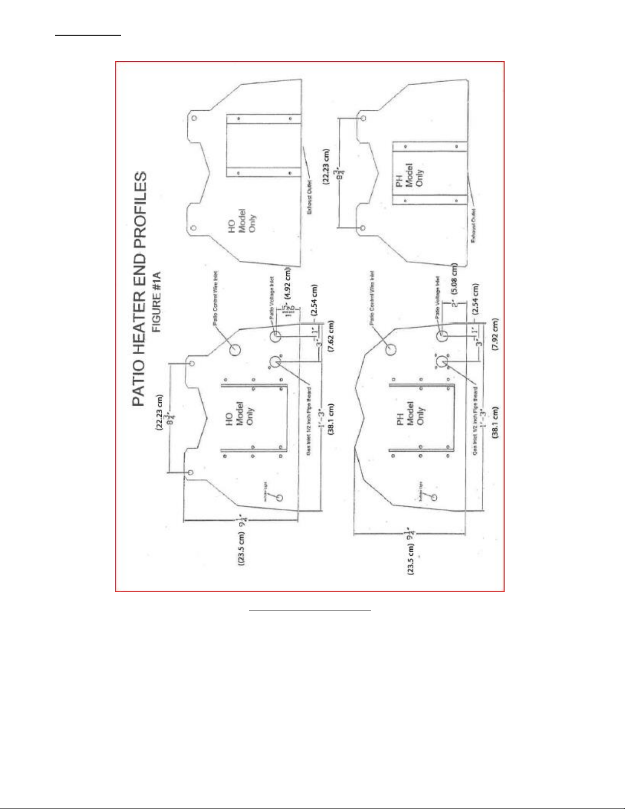
PATIO HEATER END PROFILES
Figure 2. PATIO HEATER END PROFILES
PH-SERIES
9
6.0 INSTALLATION CLEARANCES AND CLEARANCE TO COMBUSTIBLES
Installation of overhead heaters in garages or hangars MUST meet the requirements for bottom (below)
clearances detailed in CANADA: Natural Gas and Propane Installation Code, CSA B149.1 or latest edition or
USA: National Fuel Gas Code, ANSI Z223.1/NFPA 54, or latest edition.
Minimum mounting height from ground or floor to bottom portion of tube is 78" (199 cm)
WARNING: In all situations, clearances to combustibles must be maintained. Minimum clearance
from heater must be maintained from vehicles parked below heater. The posting of signs may be
required in storage areas referring to clearances to combustibles to the heater and/or limiting the
stacking height of stored Items near the heater specifying a maximum height. Clearances are not for
use in four (4) sided enclosures. Certain materials or items, when stored under the heater, will be
subjected to radiant heat and could be seriously damaged.
WARNING: For Models PH-40, 50, 75, 80, 100, and 125 when used indoors and vented accordingly,
the stated clearance to combustibles represents a surface temperature of 90°F (32°C) above room
temperature. Building material with low heat tolerance may be subject to degradation at lower
temperatures. It is the installer's responsibility to assure that adjacent material with a low heat
tolerance which may degrade at lower temperatures are protected to prevent degradation
END CLEARANCES
(BURNER HEAD END)
Minimum clearances from air intake end of burner head to object is 5" (12.7 cm).
Provide adequate accessibility clearances for servicing and proper operation. Do not install unit in such a
manner that the combustion air entering the heater is reduced in any manner
OUTDOOR APPLICATIONS ONLY
(EXHAUST END)
ALL MODELS
OUTDOOR
APPLICATIONS
ONLY
Figure 3. OUTDOOR END CLEARANCES
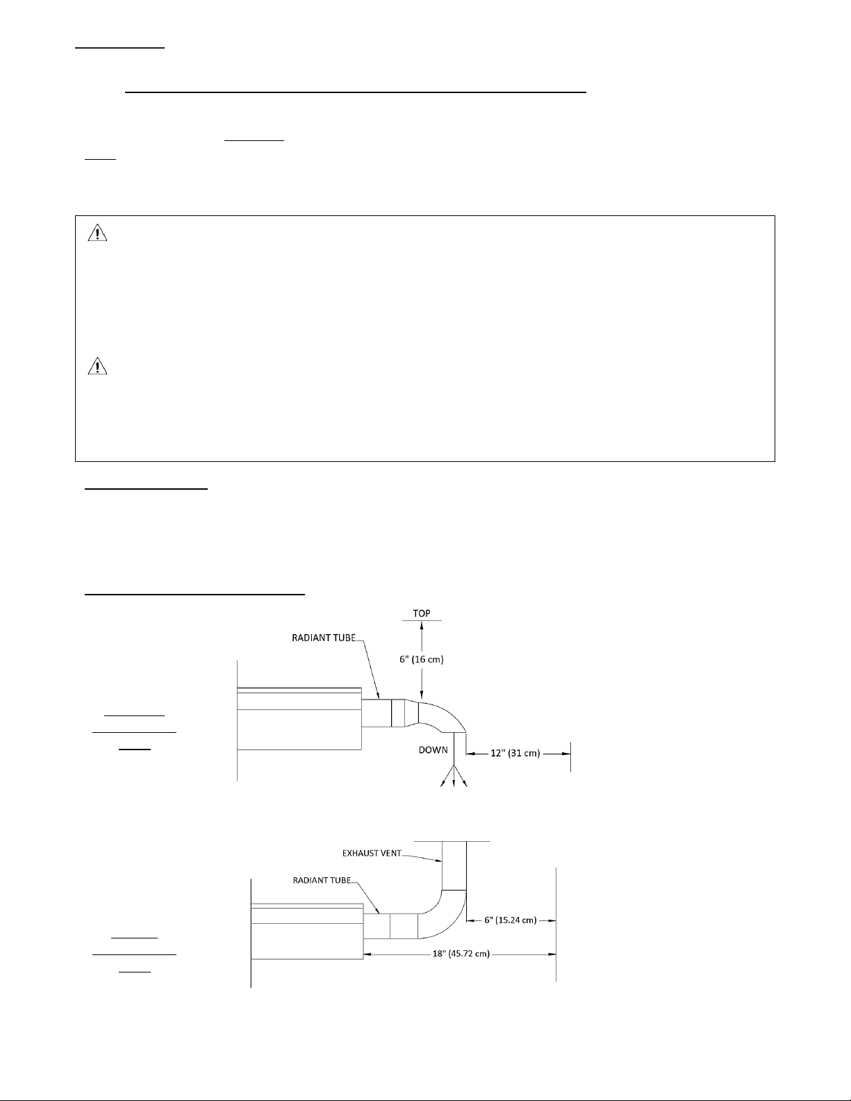
(EXHAUST END)
PH-40, 50, &
75 Only
VENTED
APPLICATIONS
ONLY
Figure 4. VENTED CLEARANCES

PH-SERIES
10
HORIZONTAL
TILT
INSTALLATION TYPE 1
INSTALLATION TYPE 2
Input* A B C D
Input* A B C D
40
4" (10.2 cm)
12" (31 cm)
34" (87 cm)
12" (31 cm)
40
4" (10.2 cm)
4" (10.2 cm)
31" (79 cm)
28" (72 cm)
50
4" (10.2 cm)
12" (31 cm)
41" (105 cm)
12" (31 cm)
50
4" (10.2 cm)
4" (10.2 cm)
35" (89 cm)
28" (72 cm)
75
4" (10.2 cm)
15" (32 cm)
46" (117 cm)
15" (32 cm)
75
4" (10.2 cm)
4" (10.2 cm)
40" (102 cm)
31" (79 cm)
40HO
8” (21 cm)
17" (44 cm)
41" (105 cm)
17" (44 cm)
40HO
8” (21 cm)
4" (10.2 cm)
28" (72 cm)
25" (64 cm)
75HO
6" (15.3 cm)
12" (31 cm)
42" (107 cm)
12" (31 cm)
75HO
6" (15.3 cm)
4" (10.2 cm)
31" (79 cm)
22" (56 cm)
Figure 5. STANDARD REFLECTOR
Figure 6. 25' TO 45' TILT
D
C
A
B
D
C
A
B

PH-SERIES
11
7.0 PRE-INSTALLATION INSPECTION:
Inspect the shipping container and heater for any evidence of shipping damage. If heater damage is found,
notify freight carrier and file a claim.
WARNING:
IF HEATER IS DAMAGED, DO NOT INSTALL
Check that all parts and pieces are present and accounted for. Report any missing items to carrier or point of
purchase at once.
Check that overall general appearance, source of fuel required and model numbers match unit requested.
Report any discrepancy to carrier or point of purchase at once.
THOROUGHLY INSPECT THE EQUIPMENT
IMMEDIATELY UPON ARRIVAL
OUR RESPONSIBILITY FOR THIS SHIPMENT CEASED WHEN THE CARRIER SIGNED THE WAYBILL.
If goods are received short or in damaged condition, it is important that you notify the carrier and insist on a
notation of the loss or damage across the face of the freight bill; otherwise no claim can be enforced against
the transportation company.
If concealed loss or damage is discovered, notify your carrier at once and request an inspection. This is
absolutely necessary. A concealed damage report must be made within 15-days of delivery of shipment. Unless
you do this, the carrier will not entertain any claim for loss or damage. The Agent will make an Inspection and
grant a concealed damage notation. If you give the Transportation Company a clear receipt for goods that have
been damaged or lost in transit, you do so at your own risk and expense.
WE ARE WILLING TO ASSIST YOU IN EVERY POSSIBLE MANNER TO COLLECT CLAIMS FOR LOSS OR DAMAGE,
BUT THIS WILLINGNESS ON OUR PART DOES NOT MAKE US RESPONSIBLE FOR COLLECTION OF CLAIMS OR
REPLACEMENT OF MATERIAL. THE ACTUAL FILING AND PROCESSING OF THE CLAIM IS YOUR RESPONSIBILITY.
WE ARE NOT RESPONSIBLE FOR FREIGHT DAMAGED IN TRANSIT!
IF CONTENTS ARE DAMAGED:
EVEN THOUGH CARTON DOES NOT LOOK DAMAGED:
A. MAKE CLAIM TO DELIVERY CARRIER AT ONCE
B. SAVE CARTONS FOR INSPECTION BY CARRIER
PH-SERIES
12
8.0 INSTALLATION
Provide for adequate clearance around air openings into the combustion chamber, clearances from
combustible material, provisions for accessibility and for combustion and ventilating air supply.
8.1 PLANNING
• Familiarize yourself with the equipment and any accessories that you may require.
• Locate the area where unit is to be installed.
• Locate area where any holes might have to be cut for:
a) Electrical and control wire.
b) Any gas piping requirements
c) Venting (PH-40, 50, 75, 80, 100, and 125 only)
• Make sure that there is no obstruction such as hidden electrical wiring, water lines etc... in the areas
of concern.
• Locate the control (All Models) and thermostat (PH-40, 50, 75, 80, 100, and 125 models indoors only)
location.
WARNING: Observe minimum clearance to combustibles.
REFER TO PAGE 9.
FOR 120 VOLT SYSTEM INSTALLATION
• Locate a grounded, adequate electrical source.
• Measure the required amount of the various materials required to do the installation, and have these
materials on site in an organized manner prior to commencement.
WARNING NOTES FOR INSTALLATION AND SUSPENSION OF THE OVERHEAD HEATER
WARNING: If the installer is to install the heater via hanging chains, it is the responsibility of the
installer to use hanging chain that has a minimum support capacity of no less than 100 lbs. Also make
sure all suspension points are adequate to support weight of heater and any accessories. Also make
sure all S-Hooks are affixed properly and the open ends squeezed closed. If the suspension system
fails, it is the responsibility of the installer.
If utilizing installation brackets or another means of suspension is used, make sure all brackets and
fasteners have sufficient load bearing capacity to satisfy the local codes as well as the extra load
that may be place upon the heater and suspension methods encountered during windy conditions.
A FAILED SUSPENSION SYSTEM CAN CAUSE PROPERT DAMAGE, SEVERE INJURY AND/OR DEATH.
THE INSTALLER TAKES FULL RESPONSIBILITY AND LIABILITY FOR THE CORRECT AND ADEQUATED
METHOD OF INSTALLATION AND SUSPENSION OF THE HEATER FOR THE CONDITIONS AND/OR
LOCATION THAT IT IS TO BE INSTALLED AT. THE SUSPENSION DETAILS IN THIS MANUAL ARE
SUGGESTIONS ONLY. IF IN DOUBT AS TO THE CORRECT METHODS TO INSTALL THIS HEATER FOR
YOUR LOCAL CODES AND CONDITIONS, DO NOT INSTALL THE HEATER. CONTACT LOCAL BUILDING
OFFICIALS FOR FURTHER INFORMATION.

PH-SERIES
13
9.0 ASSEMBLY OF COMPONENTS
WARNING: SEE PAGE 20 FOR VENTILATION REQUIREMENTS FOR THIS HEATER. MAKE SURE YOU HAVE
THE CORRECT MODEL FOR THE INTENDED APPLICATION. IF IN DOUBT CONTACT THE FACTORY FOR
DETAILS PRIOR TO INSTALLATION OR OPERATION.
9.1 GENERAL INSTRUCTIONS
Refer to figures on page 11 to 15
Note: If unit is to be installed on a 25 degree tilt refer to page 11 for this type of installation.
1) Measure and locate holes to be drilled for mounting brackets into overhead beams or
support. The PH-40, PH-40 HO and PH-75 HO have two (2) mounting locations, one at each
end. The PH-50, 75, and 80 have a third located in the center of the unit. The PH-100 has 4
and the PH-125 has 5.
2) FOR RIDGID INSTALLATION: READ WARNING ON PAGE 9 FIRST.
When installing fasteners such as bolts, inserts, threaded rod, etc, it is suggested that the
fastener(s) are no less than 3/8 inch (.9525 cm) in diameter (two (2) per hanging point) and
must penetrate and be secured in the overhead material in such a way that the unit will not
be dislodged from the mounting location during normal use and operation, including wind
load. This is the responsibility of the installing contractor and if in doubt, they shall contact the
manufacturer of the fastener chosen to verify its use. (See WARNING on page 9)
3) Lift and support preassembled unit in a safe manner, and locate where heater is to be installed.
Install fasteners through hanging brackets (optional) into the mounting material (beam, support
etc.). Then attach heater to the brackets. PH-40, 40 HO & 75 HO are now mounted. In the case
of the PH-50 & 75, the last section will have to be installed to the mounted, preassembled, first
10’. (see item #5)
4) CHAIN INSTALLATION: DO NOT USE IN WINDY CONDITIONS - READ WARNING ON PAGE 9
FIRST.
Adequately secure hanging chains as mentioned in the above item #2. Drop chains to desired
elevation and attach heater to them utilizing two lengths per hanging point.
5) PH-50 & 75: Unassembled parts. Secure end cap to one end of the reflector by over lapping
reflector onto end cap % inch, (1.905 cm) (see page 13) and secure via self tapping screws.
6) Attach the reflector assembly to the 10’ (3m) section already mounted by overlapping the
opposite reflector end onto the hanger assembly by % inch. (1.905 cm). Secure hanger on end
cap end via fasteners into the previously drilled holes located in the beam, support etc. Secure
opposite end of reflector to hanger via self tapping screws.
7) Install radiant tube by positioning three (3) inch (7.62 cm) end into end cap from below, and
butting the other end to the previously installed section. Secure clamp with self tapping
screws (see figure 9 page 13). For PH-50 tube slides over the first 10’ (3m) section tube. Secure
with screws.
8) Install decorative grille (2 - 5’ (1.53m) pieces) onto lip of reflector in a similar fashion used to
install 2x4 ceiling panels. If need be, remove some of the screws securing the reflector to the
hanger and/or end cap, spread reflector to facilitate installation, being careful not to damage
reflector, install grille and re-secure the reflector.

PH-SERIES
14
9) Install retaining clips (6 per section of screen)
10) If installing models PH-40, 50, 75, 80, 100, or 125 indoors, attach venting as per pages 22-29,
NOTE: PH40HO, PH75HO, PH-80HO, PH-100HO and PH-125HO models cannot be vented. See
page 20 for Ventilation requirements to make sure you have the correct heater for your
application.
11) Connect gas, electricity, and mount controls in a convenient location.
12) Follow guidelines for startup on page 24.
9.2 SUSPENSION DETAILS
CHAIN MOUNTING
WHEN USING CHAIN METHOD, SECURE
UNIT FROM POSSIBLE WIND DAMAGE
(See warning on Page 9)
HORIZONTAL
25 DEGREE TILT

PH-SERIES
15
Figure 7. CHAIN MOUNTING
RIGID MOUNTING
Figure 8. RIGID MOUNTING
(See warning on Page 9)
HORIZONTAL
25 DEGREE TILT
 Loading...