

Calcana PH Series, PH-40, PH-50, PH-75, PH-75 HO Specifications, Installation, Operation Service And Spare Parts Manual
...
PH-SERIES Specifications, Installation, Operation Service and Spare Parts Manual
Printed in USA © 2019 Calcana USA Ltd. Rev 5 1/19
Gas Fired Outdoor Infrared Patio Heater/Gas-Fired Infrared Patio Heater
Vented Radiant Tube Heater/ L’Appareil de chauffage de Tube Rayonnant donné vent
Gravity Vented Wall Furnace/ La gravité A Donné vent Fournaise de Mur
MODELS PH40, 50, 75, 80, 100 and 125 ONLY: For either indoor or outdoor installation/Installer à l’intérieur
ou à l’extérieur
For Industrial, Commercial, and Residential Patio and Restaurant Applications.
WARNING: Improper installation, adjustment,
alteration, service or maintenance can cause
property damage, injury or death. Read (refer to)
the installation operating and maintenance
instructions thoroughly before installing or
servicing this equipment. For assistance or
additional information consult a qualified installer,
service agency or the gas supplier.
ADVERTISSEMENT. L’installation déplacée,
l’ajustement, le changement, le service ou
l’entretien peuvent causer les dommages de
propriété, la blessure ou la mort. Lire (se référer à)
l’installation qui fonctionne et les instructions
d’entretien à fond avant d’installer ou entretenir
cet équipement. Pour obtenir de l’aide ou les
informations supplémentaires consultent un
programme d’installation, une agence de service
ou le fournisseur de gaz qualifié.
WARNING: If the information in these instructions
is not followed exactly, a fire or explosion may result;
causing property damage, personal injury or loss of
life.
ADVERTISSEMENT: Assurez-vous de bien
suivre les instructions données dans cette notice
pour réduire au minimum le risqué d’incendie ou
d’explosion ou pour éviter tout dommage
matériel, toute blessure ou la mort.
-Do not store or use gasoline or other flammable vapors
and liquids in the vicinity of this or any other appliance.
- WHAT TO DO IF YOU SMELL GAS:
1) Extinguish any open flame
2) DO NOT try to light any appliance.
3) DO NOT use or touch any electrical switches.
4) DO NOT use any phone in your building
5) Turn off gas.
6) Open Windows
7) Leave the building
8) Immediately call your gas supplier from a
neighbor’s phone or after you have left the
building. Follow the gas supplier's instructions.
9) If you cannot reach your gas supplier, call the fire
department.
- Installation and service must be performed by a
qualified installer, service agency or the gas supplier
- Ne pas entreposer ni utiliser d’essence ni d’autres
vapours ou liquidés inflammables à proximité de cet
appareil ou de tout autre appareil.
- QUE FAIRE SI VOUV SENTEZ UNE ODEUR DE GAZ:
1) Éteindre la flamme ouverte
2) Ne pas tenter d’allumer d’appareils
3) Ne touchez à aucun interrupteur.
4) Ne pas vous server des téléphonés dans le
bâtiment ou vous vous trouvez.
5) le Virage du gaz.
6) Ouvrir Windows
7) Part le bâtiment
8) Appelez immédiatement votre fournisseur de
gaz depuis un voisin ou âpres que vous êtes
parti le bâtiment. Suivez les instructions du
fournisseur.
9) Si vous ne pouvez rejoindre le service des
incendies.
- L’installation et I' entretien doivent être assures par
un installateur ou un service d’entretien qualifié ou
par fournisseur de gaz.
WARNING: Heat exchanger surface is hot. Do not touch surface or burn may result. Combustible material or articles should
not be placed on or near heater. Observe clearance to combustibles as noted on heater and in this manual.
INSTALLER: Leave this manual with the
appliance.
CONSUMER: Retain this manual for future
reference.
INSATLLATEUR: Laissez cette notice
avec I’ appareil.
CONSOMMATEUR: Conservez cette
notice pour consultation ultérieure.
Calcana USA Ltd.
30201 Country Road 49
Loxley, AL, 36551
Tel: 251-964-4400
Fax: 251-964-4404
WARNING: MODELS PH-40HO, PH-75HO, PH-80,
PH-100HO, PH-125HO Are For Outdoor Use Only

PH-SERIES
ii
WHEN AN EXISTING CATEGORY I HEATER IS REMOVED OR
REPLACED, THE ORGINAL VENTING SYSTEM MAY NO LONGER
BE SIZED TO PROPERLY VENT THE ATTACHED APPLIANCES.
The effects of an improperly sized venting system can
include but not limited to: the formation of
condensate, leakage, spillage etc. The following test
procedure is required:
WARNING
CARBON MONOXIDE POISONING HAZARD
Failure to follow the steps outlined below for each appliance connected
to the venting system being placed into operation could result in carbon
monoxide poisoning or death.
The following steps shall be followed for each appliance connected to
the venting system being placed into operation, while all other
appliances connected to the venting system are not in operation:
1) Seal any unused openings in the venting system.
2) Inspect the venting system for proper size and horizontal pitch, as
required in the National Fuel Gas Code, ANSI Z223.1/NFPA 54 or the
Natural Gas and Propane Installation Code, CSA B149.1 and these
instructions. Determine that there is no blockage or restriction,
leakage, corrosion and other deficiencies which could cause an
unsafe condition.
3) As far as practical, close all building doors and windows and all
doors between the space in which the appliance(s) connected to
the venting system are located and other spaces of the building.
4) Close fireplace dampers.
5) Turn on clothes dryers and any appliance not connected to the
venting system. Turn on any exhaust fans, such as range hoods and
bathroom exhausts, so they are operating at maximum speed. Do
not operate a summer exhaust fan.
6) Follow the lighting instructions. Place the appliance being inspected
into operation. Adjust the thermostat so appliance is operating
continuously.
7) Test for spillage from draft hood equipped appliances at the draft
hood relief opening after 5 minutes of main burner operation. Use
the flame of a match or candle.
8) If improper venting is observed during any of the above tests, the
venting system must be corrected in accordance with the National
Fuel Gas Code, ANSI Z223.1/NFPA 54 and/or Natural Gas and
Propane Installation Code, CSA B149.1.
9) After it has been determined that each appliance connected to the
venting system properly vents when tested as outlined above,
return doors, windows, exhaust fans, fireplace dampers and any
other gas-fired burning appliance to their previous conditions of use.

PH-SERIES
iii
TABLE OF CONTENTS
1.0 OWNERS RESPONSIBILITY --------------------------------- 1
2.0 INSTALLER RESPONSIBILITY------------------------------ 3
3.0 CODE COMPLIANCE ------------------------------------------ 5
4.0 SPECIFICATIONS: GENERAL SPECIFICATIONS -------- 6
5.0 PATIO HEATER SIDE DIMENSIONS ----------------------- 7
6.0 INSTALLATION CLEARANCES AND CLEARANCE TO
COMBUSTIBLES ------------------------------------------------------- 9
7.0 PRE-INSTALLATION INSPECTION: --------------------- 11
8.0 INSTALLATION ---------------------------------------------- 12
8.1 PLANNING ---------------------------------------------------------- 12
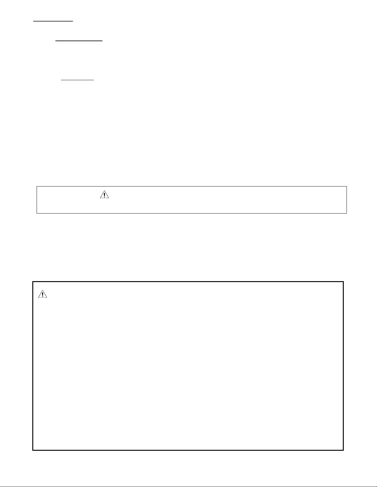
9.0 ASSEMBLY OF COMPONENTS ---------------------------- 13
9.1 GENERAL INSTRUCTIONS --------------------------------------- 13
9.2 SUSPENSION DETAILS ------------------------------------------- 14
CHAIN MOUNTING --------------------------------------------------- 14
RIGID MOUNTING ---------------------------------------------------- 15
10.0 ASSEMBLY OF COMPONENTS ---------------------------- 16
PH-50 & 75 ASSEMBLY ---------------------------------------------- 16
10.1 COMPONENT ASSEMBLY --------------------------------------- 17
JOINT HANGER TO REFLECTOR (PH-50 & 75 MODELS) ------ 17
CLAMP COUPLER (PH-50 & 75 MODELS) ----------------------- 18
END CAP TO REFLECTOR (PH-50 & 75 MODELS) -------------- 18
90° ELBOW KIT (PH-50 & 75 MODELS) -------------------------- 19
180° U-BEND KIT (PH-50 & 75 MODELS) ------------------------ 19
11.0 VENTING REQUIREMENTS ------------------------------- 20
11.1 VENTING ------------------------------------------------------------ 22
ANSI Z83.20-2016/CSA 2.34-2016 ----------------------------- 22
GAS PRODUCTS NO. 405 ------------------------------------------ 22
JANUARY 1, 2019 --------------------------------------------------- 22
VERTICAL VENTING (CONTINUED) ROOF EXHAUST : TWO OR
MORE UNITS - USE 'B' STYLE CHIMNEY. -------------------------------- 27
12.0 GAS PIPING --------------------------------------------------- 29
13.0 GAS CONNECTION ------------------------------------------ 30
HARD PIPE -------------------------------------------------------------- 30
FLEX CONNECTOR ---------------------------------------------------- 30
14.0 ELECTRICAL CONNECTION 120 VOLTS --------------- 32
14.1 120 VOLT WIRING DIAGRAM --------------------------------- 33
15.0 ELECTRICAL CONNECTION 24 VOLT (ALTERNATE
POWER SUPPLY) ---------------------------------------------------- 34
15.1 24 VOLT WIRING DIAGRAM ----------------------------------- 35
16.0 INITIAL START-UP ----------------------------------------- 36
16.1 SETTING MANIFOLD PRESSURE ------------------------------ 37
17.0 GAS INPUT RATE ------------------------------------------- 41
18.0 SEQUENCE OPERATION ----------------------------------- 42
18.1 DESCRIPTION OF 3-TRY DIRECT SPARK IGNITION
SYSTEM: ---------------------------------------------------------------------- 42
18.2 OPERATION: ------------------------------------------------------- 42
POWER UP/STANDBY ------------------------------------------------ 42
HEAT MODE ------------------------------------------------------------ 42
FLAME FAILURE - RE-IGNITION ------------------------------------ 42
19.0 TROUBLESHOOTING--------------------------------------- 43
NO POWER TO HEATER---------------------------------------------- 43
INITIAL ELECTRICAL CHECKS ---------------------------------------- 43
INITIAL GAS CHECKS -------------------------------------------------- 44
ELECTRICITY AND GAS TO HEATER, BUT STILL INOPERATIVE 44
CHECK CONTROL BOARD -------------------------------------------- 45
FAULT CONDITIONS -------------------------------------------------- 45
INTERNAL CONTROL FAULT ---------------------------------------- 45
AIRFLOW FAULT - LOCK OUT (COMBUSTION AIR FLOW
PROBLEMS) ------------------------------------------------------------------- 45
FLAME WITH NO CALL FOR HEAT (FLAME FAULT) ------------ 46
IGNITION LOCK OUT (FAILURE TO LIGHT) ----------------------- 46
FLAME SENSOR CURRENT CHECK --------------------------------- 46
PROPER ELECTRODE LOCATION ----------------------------------- 47
20.0 MAINTENANCE ---------------------------------------------- 48
CHECK COMBUSTION AIR INTAKE FOR BLOCKAGE. ----------- 48
CHECK EXHAUST TERMINAL FOR BLOCKAGE. ------------------ 48
OPEN SERVICE DOOR. ----------------------------------------------- 48
CHECK BLOWER MOTOR AND SCROLL FOR DIRT AND/OR
LOCKED ROTOR. REMOVE DIRT WITH COMPRESSED AIR OR
VACUUM CLEANER. IF ROTOR IS LOCKED, REPLACE ASSEMBLY. - 48
IF BURNER NEEDS CLEANING, REMOVE BURNER HEAD FROM
TUBE AND USE A COMBINATION OF COMPRESSED AIR AND/OR A
WIRE BRUSH TO REMOVE ANY DEPOSITS OR DEBRIS THAT MAY BE
ON THE ACTUAL BURNER. ------------------------------------------------- 48
MAKE SURE ALL WIRING IS INTACT AND IN GOOD
CONDITION. ------------------------------------------------------------------ 48
CHECK ELECTRODE FOR PROPER GAP AND CLEANLINESS.
CLEAN OR REPLACE AS NECESSARY. ------------------------------------ 48
CHECK IGNITION SYSTEM FOR SPARK. REPLACE AS
NECESSARY. ------------------------------------------------------------------ 48
CHECK EXCHANGER TUBE FOR HOLES AND/OR CRACKS, DIRT
AND/OR DEPOSITS. CLEAN AND/OR REPLACE AS NECESSARY. --- 48
WASH ANY DIRT OR JUST OFF OF THE UNIT WITH A SOAP
AND WATER SOLUTION. --------------------------------------------------- 48
CHECK ANY GAS CONNECTIONS THAT WERE DISCONNECTED
DURING MAINTENANCE FOR LEAKS. USE SOAP AND WATER
SOLUTION. DO NOT USE FLAME. ---------------------------------------- 48
TEST FIRE UNIT BY TURNING CONTROL “ON”. MAKE SURE
UNIT IS OPERATING QUIETLY AND EFFICIENTLY. --------------------- 48
PERIODICALLY VISUALLY CHECK BURNER THROUGH VIEW
PORT TO CONFIRM PROPER OPERATION. ----------------------------- 48
CHECK ALL COUPLERS FOR TIGHTNESS AND/OR LEAKAGE. - 48
21.0 PARTS: --------------------------------------------------------- 49
21.1 BURNER HEAD AND RELATED PARTS------------------------ 49
21.2 REFLECTOR AND TUBE PARTS --------------------------------- 50
21.3 PARTS LIST: --------------------------------------------------------- 51
22.0 WARRANTY -------------------------------------------------- 53
23.0 CONVERSION KIT FOR VARIABLE INPUT GAS VALVES
54
24.0 EXAMPLE OF CONVERSION KIT LABEL ---------------- 56
25.0 SAFETY AND OPERATING INSTRUCTIONS ------------ 57

PH-SERIES
iv
TABLE OF FIGURES
Figure 1. PATIO HEATER SIDE DIMENSION ............................... 7
Figure 2. PATIO HEATER END PROFILES ................................... 8
Figure 3. OUTDOOR END CLEARANCES .................................... 9
Figure 4. VENTED CLEARANCES ................................................ 9
Figure 5. STANDARD REFLECTOR ........................................... 10
Figure 6. 25' TO 45' TILT ......................................................... 10
Figure 7. CHAIN MOUNTING .................................................. 15
Figure 8. RIGID MOUNTING ................................................... 15
Figure 9. PH-50 & 75 ASSEMBLY ............................................ 16
Figure 10. JOINT HANGER INSTALLATION .............................. 17
Figure 11. CLAMP COUPLER INSTALLATION ........................... 18
Figure 12. END CAP INSTALLATION ........................................ 18
Figure 13. 90° ELBOW KIT INSTALLATION .............................. 19
Figure 14. 180° U-BEND KIT INSTALLATION ........................... 19
Figure 15. SIDE WALL VENTING, SINGLE UNIT ...................... 25
Figure 16. VERTICAL VENTING, SINGLE UNIT ........................ 26
Figure 17. COMMON VERTICAL VENTING, TWO OR MORE
UNITS INTO ONE COMMON VENT .......................................... 27
Figure 18. HARD PIPE INSTALLATION ..................................... 30
Figure 19. GAS LINE CONNECTION WITH CERTIFIED FLEXIBLE
GAS CONNECTION ................................................................... 31
Figure 20. ELECTRICAL CONNECTIONS 120 VOLT ................... 32
Figure 21. WIRING DIAGRAM 120 VOLT ................................. 33
Figure 22. ELECTRICAL CONNECTIONS 24 VOLT ..................... 34
Figure 23. WIRING DIAGRAM 24 VOLT ................................... 35
Figure 24. GAS VALVE ............................................................. 37
Figure 25. FLAME SENSOR CURRENT CHECK .......................... 46
Figure 26. PROPER ELECTRODE LOCATION ............................ 47
Figure 27. BURNER HEAD PARTS ............................................ 49
Figure 28. REFLECTOR AND TUBE PARTS ............................... 50

PH-SERIES
1
1.0 OWNERS RESPONSIBILITY
Thank you for purchasing our product. We have designed this unit to provide you with years of trouble-free
heating enjoyment.
READ THIS MANUAL IN ITS ENTIRERTY! If you do not understand any of the safety or hazardous warnings
contained in this manual, or have questions or concerns about the installation, operation, maintenance or
service of this heater, or any other questions or concerns relating to this heater, you MUST CALL THE
FACTORY at the telephone number noted on the front cover of this manual or as detailed on the rating
plate on the heater before operating this heater. Store this manual in a location near the heater, for future
reference. Make sure installation is performed by well qualified, licensed contractors in the required field of
work. If in doubt, DO NOT allow unit to be installed.
DO NOT park vehicles or place combustible objects close to the heater other than specified on the Clearance
to Combustible chart located in this manual and on the heater. Failure to observe the clearance to
combustibles can result in property damage, injury or death.
IMPORTANT NOTICE: The installation portion of these instructions are for the use of qualified individuals
specially trained, licensed and experienced in the installation of this type of equipment and related system
components.
NOTE: - The words "shall" or "must" indicate a requirement which is essential to satisfactory and safe
performance.
GENERAL HAZARD WARNING: The heater and related gas piping, fitting & wiring must be installed
by individuals or firms qualified, licensed and specially trained and experienced in installation of this
type of equipment and related system components.
Only persons who can understand and follow the instructions shall install or service this heater.
Persons not qualified shall not install this equipment nor interpret these instructions.
Failure to comply with the precautions and instructions provided with this heater can result in death,
serious bodily injury and property loss or damage from hazards of fire, explosion, burn, asphyxiation,
carbon monoxide poisoning or electrical shock.
WARNING: Installation and repair should be done by a qualified service person. The heater should be
inspected before use and at least annually by a qualified service person and prior to heating season.
Heaters used in dusty locations such as brooder barns, sawmills, woodworking shops, etc. will require
maintenance on a more regular basis and more frequent cleaning may be required as necessary. It is
imperative that the control compartments, burner(s) and circulating air passageways of the appliance
be kept clean. Periodic examination of the venting system is to be performed.
No one should work on a heater unless they are a licensed/qualified gas fitter or contractor. For all
repairs, parts MUST originate from the manufacturer of this heater in order not to void CGA/AGA
certification. Safety devices are not allowed to be rendered inoperative and left unattended as this
action can cause property damage, injury or death. Failure to do so will void your warranty.

PH-SERIES
2
WARNING: Improper installation, adjustment, alteration, servicing or maintenance can cause property
damage, injury, or death
WARNING: Children and adults should be alerted to the hazards of high surface temperatures and should
stay away to avoid burns or clothing ignition.
Young children should be carefully supervised when they are in the same place as the heater.
Clothing or other flammable materials should not be hung from the heater, or placed on or near the
heater.
Any guard or other protective device removed for servicing a heater must be replaced prior to operating
the heater.
WARNING: MODELS PH-40HO and PH-75HO ONLY: These appliances shall be used only outdoors in a
well-ventilated space and shall not be used in a building, garage or any other enclosed area.
WARNING: California Proposition 65
If not installed, operated and maintained in accordance with manufacturer’s instructions. This product
could expose you to substances in the fuel or from combustion which can cause death or serious illness
and which are known to the State of California to cause cancer, birth defects or reproductive harm.
Do not use this appliance if any part has been under water. Immediately call a qualified service technician
to inspect the appliance and to replace any part of the control system and any gas control which has been
under water.
Ne pas se server de cet appareil sil a été plongé dans I ‘eau, complètement ou en partie, Faire inspecter I’
appareil par un technicien qualifié et remplacer toute partie du système de control et toute commande
qui ont été plongée dans I’ eau.
WARNING: SEE PAGE 15A FOR VENTILATION REQUIREMENTS FOR THIS HEATER. MAKE SURE YOU HAVE
THE CORRECT MODEL FOR THE INTENDED APPLICATION. IF IN DOUBT CONTACT THE FACTORY FOR
DETAILS PRIOR TO INSTALLATION OR OPERATION.

PH-SERIES
3
2.0 INSTALLER RESPONSIBILITY
WARNING:
FIRE OR EXPLOSION HAZARD
The heater and related gas piping and wiring must be installed only by individuals or firms well qualified and
licensed in the required field of work.
Read and understand this manual in its entirety BEFORE you install this heater. If you have any questions call
your local representative. Verify that the fuel on the installation site is the same as what is required for this
heater. Check heater for damage or missing parts. If damage has occurred, notify carrier or point of purchase
at once for reconciliation of damaged goods. We are not responsible for transit damage. Do not install if
heater is damaged.
If you do not understand any of the safety or hazardous warnings contained in this manual, or have
questions or concerns about the installation, operation, maintenance or service of this heater, or any other
questions or concerns relating to this heater, you MUST CALL THE FACTORY at the telephone number noted
on the front cover of this manual or as detailed on the rating plate on the heater before operating this
heater.
Verify that model, input & length is what was ordered and is appropriate for installation. This appliance shall
be use only outdoors in a well ventilated space and shall not be used in a building, garage, or any other
enclosed area.
Installation shall be in accordance with local codes. (See ‘CODE COMPLIANCE’).
If installation requires tilting, DO NOT over tilt the unit. Units are certified for installations up to 25°.
Install unit according to the “Clearance to Combustibles” for that particular heater and type of installation.
Make sure that clearances are maintained from vehicles parked below or in front of heater. Failure to do so
could result in property damage, injury or death.
Make sure unit is adequately suspended from ceiling or roof. Select hanging location that has adequate
strength to support heater.
Adequate clearance around air openings into the combustion chamber, clearance from combustible material,
provisions for accessibility and for combustion and ventilation air supply.
Do not render safety devices inoperable. Make sure gas line and/or service have adequate capacity for the
increased load of heater.
Check line and manifold pressure with a manometer to confirm unit is set according to the specification on
the rating plate. Perform check with all gas-fired appliances operating. (see gas manifold test)
Provide adequate accessibility clearances for servicing.
Leave copy of this manual with owner (or a copy) for future reference.
This heater needs fresh air for safe operation and must be installed so there are provisions for adequate
combustion and ventilation air. . If in a confined space make sure model of heater can be installed and
attached to either a sidewall or roof vent. Models PH-40, 50, 75, 80, 100 and 125 can be installed in this
fashion.
Continued on page 4
WARNING:
PH-SERIES
4
FIRE OR EXPLOSION HAZARD
The PH-40, 50, 75, 80, 100, and 125 heaters must not be connected to a chimney flue serving a separate solidfuel burning appliance. These models, in a space heating application, must only be installed with the venting
that they are certified for. Refer to the installation instructions for installation details. If you are installing a
PH-40, 50, 75, 80, 100, and 125 unit indoors it will need to be vented either with a sidewall vent kit, (use pin
#800208 sidewall vent kit) or via a certified “B” vent system through the roof. For side wall applications, make
sure vent cap is past eave (See venting section for both types of installation) PH-40HO, PH-75HO, PH-80HO,
PH-100HO and PH-125HO units are for outdoor applications only.
Make sure units are operating as quiet and efficient a possible before leaving the job site and instruct owner/s
on the safe operation of the heater as well as safety and hazardous issues as they relate to the heater, it’s
installation, operation and this manual.
Leave this manual with the consumer and instruct them to retain the manual for future reference.
WARNING:
California Proposition 65
If not installed, operated and maintained in accordance with manufacturer's instructions. This product could
expose you to substances in the fuel or from combustion which can cause death or series illness and which
are known to the State of California to cause cancer, birth defects or reproductive harm.
HEATER OPERATION NOTE: PH-40, 50, 75, 80, 100, and 125 Patio Heaters will have a higher heat output at
the burner end as compared to the exhaust end.
SPACE HEATING: As a general rule, it is suggested to locate the burner end toward the highest heat-loss area
(doors) of the space being heated. If you have any concerns or questions concerning orientation or layout of
the heater in your application, contact factory for assistance.
SPOT HEATING: On PH-40, 50, 75, 80, 100, and 125 heaters with a straight line configuration, there will be a
noticeable and more pronounced perception of greater heat output from the burner end of the heater as
compared to the exhaust end. As a general rule, it Is suggested for spot heating applications, to use the PH-
40HO, PH-75HO, PH-80HO, PH-100HO or PH-125HO models or a u-tube configuration to provide a more even
source of heat; or two units, side by side with the burner heads at opposite ends to promote even heating. If
you have any concerns or questions concerning orientation or layout of the heater in your application,
contact factory for assistance.
NOTE: A small amount of condensation may occur from the heater when it starts the heating cycle. The
condensation will stop once the heater warms up. On models PH-40, 50, 75, 80, 100, and 125 and if using a
venting system, make sure venting is sealed and installed according to section title VENTING
PH-SERIES
5
3.0 CODE COMPLIANCE
Installation shall be in accordance with local building codes, or in the absence of local codes, in accordance
with:
FUEL SUPPLY:
CANADA: Natural Gas and Propane Installation Code, CSA B149.1 or latest edition.
USA: National Fuel Gas Code, ANSI Z223.1/NFPA 54, or latest edition.
ELECTRICAL GROUNDING:
CANADA: Canadian Electrical Code, CSA C22.1 or latest edition.
USA: National Electrical Code, ANSI/NFPA 70 or latest edition
In Canada: Electrical equipment and wiring shall comply with the applicable provisions of the current
Canadian Electrical Code, CAN/CSA C22.1, Part I and Part II, and CAN/CSA C22.2 No.3, Electrical
features of Fuel Burning Equipment.
WARNING: SEE PAGE 20 FOR VENTILATION REQUIREMENTS FOR THIS HEATER. MAKE SURE YOU HAVE
THE CORRECT MODEL FOR THE INTENDED APPLICATION. IF IN DOUBT CONTACT THE FACTORY FOR
DETAILS PRIOR TO INSTALLATION OR OPERATION.

PH-SERIES
6
4.0 SPECIFICATIONS: GENERAL SPECIFICATIONS
Rating: (Input: Natural and Propane Gas)
In Canada: 0-4500' (1372 m) In USA: 0-2000' (610 m) - De-rate Above 2000' (610 m) (see page 37)
MODEL
BURNER INPUT BTU/hr
TUBE LENGTH
MIN
MAX
PH-40
20,000
40,000
137” (341 cm)
PH-40 HO
20,000
50,000
64” (163 cm)
PH-50
25,000
50,000
197” (501 cm)
PH-75
37,500
75,000
257” (653 cm)
PH-75 HO
37,500
75,000
124” (315 cm)
PH-80
40,000
80,000
257” (653 cm)
PH-80HO
40,000
80,000
124” (315 cm)
PH-100
50,000
100,000
377” (957.58 cm)
PH-100HO
50,000
100,000
197” (501 cm)
PH-125
62,500
125,000
497” (1262.38 cm)
PH-125HO
62,500
125,000
257” (653 cm)
GAS PRESSURE at MANIFOLD:
Natural Gas:
Lo: 1.5" (3.8 cm) W.C.
Hi 3.5" (8.89 cm) W.C.
Proppane Gas:
Lo: 5.5" (13.97 cm) W.C.
Hi: 10.5" (26.67 cm) W.C.
Gas Connection
0.5" (1.27 cm) N.P.T.
GAS INLET PRESSURE:
GAS:
MINIMUM:
MAXIMUM:
Natural
4.5" (11.43 cm) W.C.
14.0" (35.56 cm) W.C.
Propane
11.5" (29.21 cm) W.C.
14.0" (35.56 cm) W.C.
FOR MODELS PH-40, 50, & 75 ONLY:
Vent Connection is 3" (7.62 cm)
ELECTRICAL RATING:
DSI Ignition, 120v. 60 Hz, 1 Amps, Appliance, 24 volt low voltage control.
STANDARD EQUIPMENT:
Burner control housing is pre-assembled and pre-wired; unit comes complete with the following: industry
standard gas, electrical and venting connections, balanced air rotor, thermal overload protected motor, visual
burner inspection sight glass, combustion and air proving safety switches, 3-try spark ignition control, low
voltage control connection, aluminized heat-treated steel combustion tube, polished aluminum standard
reflector, aluminized steel radiant heat exchanger, tube couplers, joint/hanger pieces, heat economizer baffle,
wave concentrator, grille, variable input control and remote control panel.
Optional Equipment:
- 90° Elbow Kit (PH-50, 75, 80, 100, 125 Only)
- 180° U-Bend Kit (PH-50, 75, 80, 100, 125 Only)
- Stainless Steel Construction
- 24 Volt input
- Hanging Brackets

PH-SERIES
7
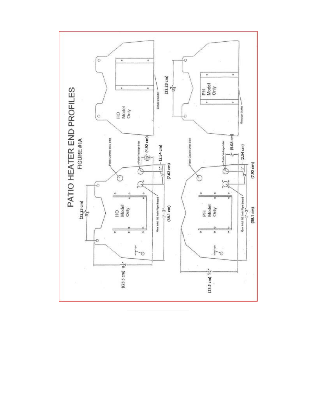
5.0 PATIO HEATER SIDE DIMENSIONS
PATIO HEATER SIDE DIMENSIONS
Figure 1. PATIO HEATER SIDE DIMENSION
PH-SERIES
8
PATIO HEATER END PROFILES
Figure 2. PATIO HEATER END PROFILES
PH-SERIES
9
6.0 INSTALLATION CLEARANCES AND CLEARANCE TO COMBUSTIBLES
Installation of overhead heaters in garages or hangars MUST meet the requirements for bottom (below)
clearances detailed in CANADA: Natural Gas and Propane Installation Code, CSA B149.1 or latest edition or
USA: National Fuel Gas Code, ANSI Z223.1/NFPA 54, or latest edition.
Minimum mounting height from ground or floor to bottom portion of tube is 78" (199 cm)
WARNING: In all situations, clearances to combustibles must be maintained. Minimum clearance
from heater must be maintained from vehicles parked below heater. The posting of signs may be
required in storage areas referring to clearances to combustibles to the heater and/or limiting the
stacking height of stored Items near the heater specifying a maximum height. Clearances are not for
use in four (4) sided enclosures. Certain materials or items, when stored under the heater, will be
subjected to radiant heat and could be seriously damaged.
WARNING: For Models PH-40, 50, 75, 80, 100, and 125 when used indoors and vented accordingly,
the stated clearance to combustibles represents a surface temperature of 90°F (32°C) above room
temperature. Building material with low heat tolerance may be subject to degradation at lower
temperatures. It is the installer's responsibility to assure that adjacent material with a low heat
tolerance which may degrade at lower temperatures are protected to prevent degradation
END CLEARANCES
(BURNER HEAD END)
Minimum clearances from air intake end of burner head to object is 5" (12.7 cm).
Provide adequate accessibility clearances for servicing and proper operation. Do not install unit in such a
manner that the combustion air entering the heater is reduced in any manner
OUTDOOR APPLICATIONS ONLY
(EXHAUST END)
ALL MODELS
OUTDOOR
APPLICATIONS
ONLY
Figure 3. OUTDOOR END CLEARANCES
(EXHAUST END)
PH-40, 50, &
75 Only
VENTED
APPLICATIONS
ONLY
Figure 4. VENTED CLEARANCES

PH-SERIES
10
HORIZONTAL
TILT
INSTALLATION TYPE 1
INSTALLATION TYPE 2
Input* A B C D
Input* A B C D
40
4" (10.2 cm)
12" (31 cm)
34" (87 cm)
12" (31 cm)
40
4" (10.2 cm)
4" (10.2 cm)
31" (79 cm)
28" (72 cm)
50
4" (10.2 cm)
12" (31 cm)
41" (105 cm)
12" (31 cm)
50
4" (10.2 cm)
4" (10.2 cm)
35" (89 cm)
28" (72 cm)
75
4" (10.2 cm)
15" (32 cm)
46" (117 cm)
15" (32 cm)
75
4" (10.2 cm)
4" (10.2 cm)
40" (102 cm)
31" (79 cm)
40HO
8” (21 cm)
17" (44 cm)
41" (105 cm)
17" (44 cm)
40HO
8” (21 cm)
4" (10.2 cm)
28" (72 cm)
25" (64 cm)
75HO
6" (15.3 cm)
12" (31 cm)
42" (107 cm)
12" (31 cm)
75HO
6" (15.3 cm)
4" (10.2 cm)
31" (79 cm)
22" (56 cm)
Figure 5. STANDARD REFLECTOR
Figure 6. 25' TO 45' TILT
D
C
A
B
D
C
A
B

PH-SERIES
11
7.0 PRE-INSTALLATION INSPECTION:
Inspect the shipping container and heater for any evidence of shipping damage. If heater damage is found,
notify freight carrier and file a claim.
WARNING:
IF HEATER IS DAMAGED, DO NOT INSTALL
Check that all parts and pieces are present and accounted for. Report any missing items to carrier or point of
purchase at once.
Check that overall general appearance, source of fuel required and model numbers match unit requested.
Report any discrepancy to carrier or point of purchase at once.
THOROUGHLY INSPECT THE EQUIPMENT
IMMEDIATELY UPON ARRIVAL
OUR RESPONSIBILITY FOR THIS SHIPMENT CEASED WHEN THE CARRIER SIGNED THE WAYBILL.
If goods are received short or in damaged condition, it is important that you notify the carrier and insist on a
notation of the loss or damage across the face of the freight bill; otherwise no claim can be enforced against
the transportation company.
If concealed loss or damage is discovered, notify your carrier at once and request an inspection. This is
absolutely necessary. A concealed damage report must be made within 15-days of delivery of shipment. Unless
you do this, the carrier will not entertain any claim for loss or damage. The Agent will make an Inspection and
grant a concealed damage notation. If you give the Transportation Company a clear receipt for goods that have
been damaged or lost in transit, you do so at your own risk and expense.
WE ARE WILLING TO ASSIST YOU IN EVERY POSSIBLE MANNER TO COLLECT CLAIMS FOR LOSS OR DAMAGE,
BUT THIS WILLINGNESS ON OUR PART DOES NOT MAKE US RESPONSIBLE FOR COLLECTION OF CLAIMS OR
REPLACEMENT OF MATERIAL. THE ACTUAL FILING AND PROCESSING OF THE CLAIM IS YOUR RESPONSIBILITY.
WE ARE NOT RESPONSIBLE FOR FREIGHT DAMAGED IN TRANSIT!
IF CONTENTS ARE DAMAGED:
EVEN THOUGH CARTON DOES NOT LOOK DAMAGED:
A. MAKE CLAIM TO DELIVERY CARRIER AT ONCE
B. SAVE CARTONS FOR INSPECTION BY CARRIER
PH-SERIES
12
8.0 INSTALLATION
Provide for adequate clearance around air openings into the combustion chamber, clearances from
combustible material, provisions for accessibility and for combustion and ventilating air supply.
8.1 PLANNING
• Familiarize yourself with the equipment and any accessories that you may require.
• Locate the area where unit is to be installed.
• Locate area where any holes might have to be cut for:
a) Electrical and control wire.
b) Any gas piping requirements
c) Venting (PH-40, 50, 75, 80, 100, and 125 only)
• Make sure that there is no obstruction such as hidden electrical wiring, water lines etc... in the areas
of concern.
• Locate the control (All Models) and thermostat (PH-40, 50, 75, 80, 100, and 125 models indoors only)
location.
WARNING: Observe minimum clearance to combustibles.
REFER TO PAGE 9.
FOR 120 VOLT SYSTEM INSTALLATION
• Locate a grounded, adequate electrical source.
• Measure the required amount of the various materials required to do the installation, and have these
materials on site in an organized manner prior to commencement.
WARNING NOTES FOR INSTALLATION AND SUSPENSION OF THE OVERHEAD HEATER
WARNING: If the installer is to install the heater via hanging chains, it is the responsibility of the
installer to use hanging chain that has a minimum support capacity of no less than 100 lbs. Also make
sure all suspension points are adequate to support weight of heater and any accessories. Also make
sure all S-Hooks are affixed properly and the open ends squeezed closed. If the suspension system
fails, it is the responsibility of the installer.
If utilizing installation brackets or another means of suspension is used, make sure all brackets and
fasteners have sufficient load bearing capacity to satisfy the local codes as well as the extra load
that may be place upon the heater and suspension methods encountered during windy conditions.
A FAILED SUSPENSION SYSTEM CAN CAUSE PROPERT DAMAGE, SEVERE INJURY AND/OR DEATH.
THE INSTALLER TAKES FULL RESPONSIBILITY AND LIABILITY FOR THE CORRECT AND ADEQUATED
METHOD OF INSTALLATION AND SUSPENSION OF THE HEATER FOR THE CONDITIONS AND/OR
LOCATION THAT IT IS TO BE INSTALLED AT. THE SUSPENSION DETAILS IN THIS MANUAL ARE
SUGGESTIONS ONLY. IF IN DOUBT AS TO THE CORRECT METHODS TO INSTALL THIS HEATER FOR
YOUR LOCAL CODES AND CONDITIONS, DO NOT INSTALL THE HEATER. CONTACT LOCAL BUILDING
OFFICIALS FOR FURTHER INFORMATION.

PH-SERIES
13
9.0 ASSEMBLY OF COMPONENTS
WARNING: SEE PAGE 20 FOR VENTILATION REQUIREMENTS FOR THIS HEATER. MAKE SURE YOU HAVE
THE CORRECT MODEL FOR THE INTENDED APPLICATION. IF IN DOUBT CONTACT THE FACTORY FOR
DETAILS PRIOR TO INSTALLATION OR OPERATION.
9.1 GENERAL INSTRUCTIONS
Refer to figures on page 11 to 15
Note: If unit is to be installed on a 25 degree tilt refer to page 11 for this type of installation.
1) Measure and locate holes to be drilled for mounting brackets into overhead beams or
support. The PH-40, PH-40 HO and PH-75 HO have two (2) mounting locations, one at each
end. The PH-50, 75, and 80 have a third located in the center of the unit. The PH-100 has 4
and the PH-125 has 5.
2) FOR RIDGID INSTALLATION: READ WARNING ON PAGE 9 FIRST.
When installing fasteners such as bolts, inserts, threaded rod, etc, it is suggested that the
fastener(s) are no less than 3/8 inch (.9525 cm) in diameter (two (2) per hanging point) and
must penetrate and be secured in the overhead material in such a way that the unit will not
be dislodged from the mounting location during normal use and operation, including wind
load. This is the responsibility of the installing contractor and if in doubt, they shall contact the
manufacturer of the fastener chosen to verify its use. (See WARNING on page 9)
3) Lift and support preassembled unit in a safe manner, and locate where heater is to be installed.
Install fasteners through hanging brackets (optional) into the mounting material (beam, support
etc.). Then attach heater to the brackets. PH-40, 40 HO & 75 HO are now mounted. In the case
of the PH-50 & 75, the last section will have to be installed to the mounted, preassembled, first
10’. (see item #5)
4) CHAIN INSTALLATION: DO NOT USE IN WINDY CONDITIONS - READ WARNING ON PAGE 9
FIRST.
Adequately secure hanging chains as mentioned in the above item #2. Drop chains to desired
elevation and attach heater to them utilizing two lengths per hanging point.
5) PH-50 & 75: Unassembled parts. Secure end cap to one end of the reflector by over lapping
reflector onto end cap % inch, (1.905 cm) (see page 13) and secure via self tapping screws.
6) Attach the reflector assembly to the 10’ (3m) section already mounted by overlapping the
opposite reflector end onto the hanger assembly by % inch. (1.905 cm). Secure hanger on end
cap end via fasteners into the previously drilled holes located in the beam, support etc. Secure
opposite end of reflector to hanger via self tapping screws.
7) Install radiant tube by positioning three (3) inch (7.62 cm) end into end cap from below, and
butting the other end to the previously installed section. Secure clamp with self tapping
screws (see figure 9 page 13). For PH-50 tube slides over the first 10’ (3m) section tube. Secure
with screws.
8) Install decorative grille (2 - 5’ (1.53m) pieces) onto lip of reflector in a similar fashion used to
install 2x4 ceiling panels. If need be, remove some of the screws securing the reflector to the
hanger and/or end cap, spread reflector to facilitate installation, being careful not to damage
reflector, install grille and re-secure the reflector.

PH-SERIES
14
9) Install retaining clips (6 per section of screen)
10) If installing models PH-40, 50, 75, 80, 100, or 125 indoors, attach venting as per pages 22-29,
NOTE: PH40HO, PH75HO, PH-80HO, PH-100HO and PH-125HO models cannot be vented. See
page 20 for Ventilation requirements to make sure you have the correct heater for your
application.
11) Connect gas, electricity, and mount controls in a convenient location.
12) Follow guidelines for startup on page 24.
9.2 SUSPENSION DETAILS
CHAIN MOUNTING
WHEN USING CHAIN METHOD, SECURE
UNIT FROM POSSIBLE WIND DAMAGE
(See warning on Page 9)
HORIZONTAL
25 DEGREE TILT

PH-SERIES
15
Figure 7. CHAIN MOUNTING
RIGID MOUNTING
Figure 8. RIGID MOUNTING
(See warning on Page 9)
HORIZONTAL
25 DEGREE TILT
PH-SERIES
16
10.0 ASSEMBLY OF COMPONENTS
PH-50 & 75 ASSEMBLY
Figure 9. PH-50 & 75 ASSEMBLY
PH-SERIES
17
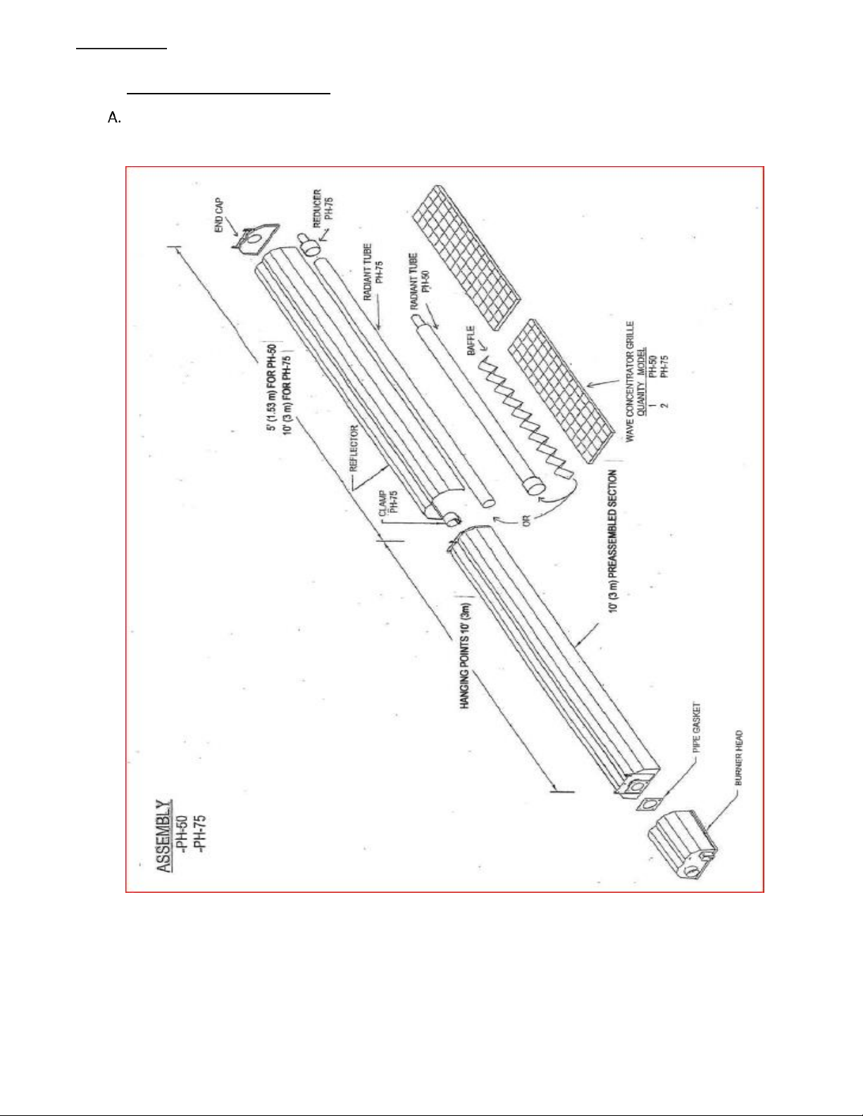
10.1 COMPONENT ASSEMBLY
JOINT HANGER TO REFLECTOR
(PH-50 & 75 MODELS)
Figure 10. JOINT HANGER INSTALLATION

PH-SERIES
18
CLAMP COUPLER
(PH-50 & 75 MODELS)
Figure 11. CLAMP COUPLER INSTALLATION
END CAP TO REFLECTOR
(PH-50 & 75 MODELS)
Figure 12. END CAP INSTALLATION

PH-SERIES
19
90° ELBOW KIT
(PH-50 & 75 MODELS)
Figure 13. 90° ELBOW KIT INSTALLATION
180° U-BEND KIT
(PH-50 & 75 MODELS)
Figure 14. 180° U-BEND KIT INSTALLATION

PH-SERIES
20
11.0 VENTING REQUIREMENTS
(UNVENTED APPLICATIONS: (All Models)
This appliance shall only be used in a well vented space and shall not be used in a building, garage or any other
enclosed or semi enclosed space unless the space conforms to the specifications under the sections titled: "FOR
UNVENTED INSTALLATIONS IN SEMI ENCLOSED APPLICATIONS" or "FOR VENTED INSTALLATIONS”
If no other means of ventilation is provided (either mechanical or natural ventilation) in the area to be heated,
an appliance may be installed with shelter no more inclusive than:
a) With walls on all sides, but no overhead cover.
b) Within a partial enclosure which includes an overhead cover and no more than two side walls. These side
walls may be parallel, as in a breezeway, or at right angles to each other.
c) Within a partial enclosure which includes an overhead cover and three side walls, as long as 30 percent or
more of the horizontal periphery of the enclosure is permanently open.
FOR UNVENTED INSTALLATIONS IN SEMI ENCLOSED APPLICATIONS: (All models)
If the heater is to be used or installed in a semi enclosed application, which Is more confining than as described
under the section titled "UNVENTED APPLICATIONS" but is not totally enclosed; adequate ventilation must be
provided to dilute the products of combustion. This rate is a minimum of four (4) CFM (cubic feet per minute)
or .12 cubic meters per 1000 BTU/Hr of installed heater input. Ventilation is to be provided via mechanical or
natural gravity (convection). Provision must be provided for adequate fresh, outdoor air to enter the space
through either, building crack-age and/or fresh air ventilation inlets and/or mechanical exhaust and/or supply
fans. Contact local authorities for verification of local code compliance prior to operation.
If adequate ventilation cannot be provided, a condition can occur whereby the exhaust gases can displace the
available air at ceiling level to such an extent that the heater may not operate properly and cause one or all of
the following symptoms: black residue at the exhaust outlet (soot) and /or backfiring and/or complete heater
shutdown. In order to eliminate this possible condition, do not install this heater in recessed ceiling applications
that are not ventilated (if clarification of this type of installation is required, call the factory for further
information prior to installation or purchase), or In situations where the products of combustions cannot
escape or be ventilated at a rate sufficient to support combustion. Ventilation in tray ceiling or peak ceiling
applications can be via mechanical ventilation, or natural convection though ventilation and exhaust inlets or
grilles at a minimum rate of four (4) CFM (cubic feet per minute) or .12 cubic meters per 1000 BTU/Hr of
installed heater input.
If you do not understand or are unfamiliar with the terminology or instruction as they are written, do not
install this product until you contact the local authorities for clarification or approval.

PH-SERIES
21
FOR VENTED INSTALLTIONS: (For PH -4O, 50, 75, 80, 100 and 125 models only)
WARNING: DO NOT ATTEMPT TO CONNECT ANY HO (HIGH OUTPUT) MODEL TO ANY VENTING.
If adequate ventilation cannot be provided by the methods previously described under the heading "FOR
UNVENTED INSTALLATIONS IN SEMI ENCLOSED APPLICATIONS", an approved chimney or sidewall venting
system must be used. Only models PH-40, 50, 75, 80, 100 and 125 can be connected to an approved venting
system.
If you have an HO model and cannot provide adequate ventilation to safely operate the unit as per the previous
heading ("FOR UNVENTED INSTALLATIONS IN SEMI ENCLOSED APPLICATIONS"), return unit to your supplier and
purchase the appropriate model for this type of application.
If you do not understand or are unfamiliar with how to vent a gas fired appliance, do not install this product
until you contact the local authorities for clarification or approval.
To connect to an approved chimney (by others) or side wall vent system (Part #800208) remove the exhaust
hood from the end cap by drilling out four (4) retaining rivets and discarding the hood. The exposed tubing is 3"
I.D. and can be connect to an approved venting system by following the instructions on appropriates pages (22-
29) for your particular installation.
If the roof/chimney type installation is selected also adhere to any instructions supplied by the manufacturer of
the system.

PH-SERIES
22
11.1 VENTING
ANSI Z83.20-2016/CSA 2.34-2016
GAS PRODUCTS NO. 405
JANUARY 1, 2019
APPROVED CATEGORY III Venting Method
In North America (Canada and the USA) the SPECIAL VENTING method, as detail below, is approved as a Category
III venting system for Calcana installations where venting is required.
The venting system is to be provided by the installer. The use of readily available, single wall venting materials
with a thickness no less than 26 gauge is to be used. If 26 gauge “C-vent” or galvanized “stove pipe” is selected,
each joint will need to be sealed with high temperature silicone as prescribed below, as well as the connection
will require a minimum of three (3) #8 sheet metal or self tapping screws to be used in a pattern such that each
screw is installed at a distance that is equal between the number of fasteners selected. If material other than
the aforementioned is employed, connect sections of material in such a fashion that each connection is secure
and sealed. A minimum 36” (91 cm) length of 3” (7.62 cm) (PH-40, PH-50,PH-75) or 4” (10 cm) (for PH-40, PH50, PH-75, PH-80, PH-100, PH-125) single wall material, with a thickness no less than 26 gauge is to be installed
at the exhaust end of heater. This length can include elbows. If a portion of venting is to pass through a wall,
installer can continue the single wall vent as long as a combustible wall thimble is used to provide adequate
clearance to combustibles, or “B-vent (and related accessories) can be used. If a portion of venting is to pass
through a roof, installer to use “B-vent” (and related accessories) for these sections. Use approved chimney cap
for vertical installations and approved high wind terminal, as described below in subsection B and C for
HORIZONTAL VENTING. Installer is to adequately support vent system to prevent sagging in a manner that is in
accordance with codes for the area.
Installer is to make sure all flue joints are sealed. Use only suitable products equal to General Electric RTV106 or
Permatex 81160 High-Temp Red RTV, Red High Temperature Silicone Adhesive Sealant (not supplied). Apply a
minimum of ¼ “ x ¼” (6.35mm x 6.35 mm) bead of silicone to each joint, and to each seam. The bead should be
applied to venting material with a smaller diameter as compared to the larger opening of the mating material or
in some instances, clamp, in such a fashion that when the joint is secured, the silicone is squeezed between the
two materials to form a sealed connection. Apply additional silicone if needed to accomplish a sealed joint or
seam.
Follow the silicone manufacturer’s instructions for curing, and after the material has cured, the installer is to
perform a leak test on the venting system. A soap and water solution test, on the venting installed inside the
occupied space, can be used. If seamed, 26 gauge “C-vent” material is used, seal seam(s) with RTV high
temperature silicone. Once the installer is satisfied that the venting system is sealed, the heater can be placed
in permanent operation.

PH-SERIES
23
HORIZONTAL AND VERTICAL VENTING APPLICATIONS
Venting of the unit must comply with the Installation Codes CAN/CGA-B149.1. In the USA, refer to NATIONAL
FUEL CODE ANSI Z223.1/NFPA 54; current edition or local codes.
Select exhaust point:
A vent shall not terminate:
a. within 6 feet (1.8 m) of a mechanical air supply inlet to a building;
b. above a meter/regulator assembly within 3 feet (.9 m) horizontally of the vertical center line of
the regulator,
c. within 6 feet (1.8 m) of any gas service regulator vent outlet,
d. less than 1 foot (.3 m) above grade level;
e. less than 7 feet (2.1 m) above a paved sidewalk or a paved highway;
f. within 3 feet (.3 m) of a Window or door which can be opened in any building , any non-
mechanical air supply inlet to any building or the combustion air Inlet or any other appliances.
NOTE: May be reduced to 1 foot for inputs up to 100,000 BTUH (30kW) and 3 feet (.9 m) for inputs exceeding
100,000 BTUH.
In the U.S.: The National Fuel Gas code, ANSI Z223.1/NFPA 54, specifies a 4 foot (1.22 m) vent
terminal clearance from gas and electrical meters, regulators and relief equipment.

PH-SERIES
24
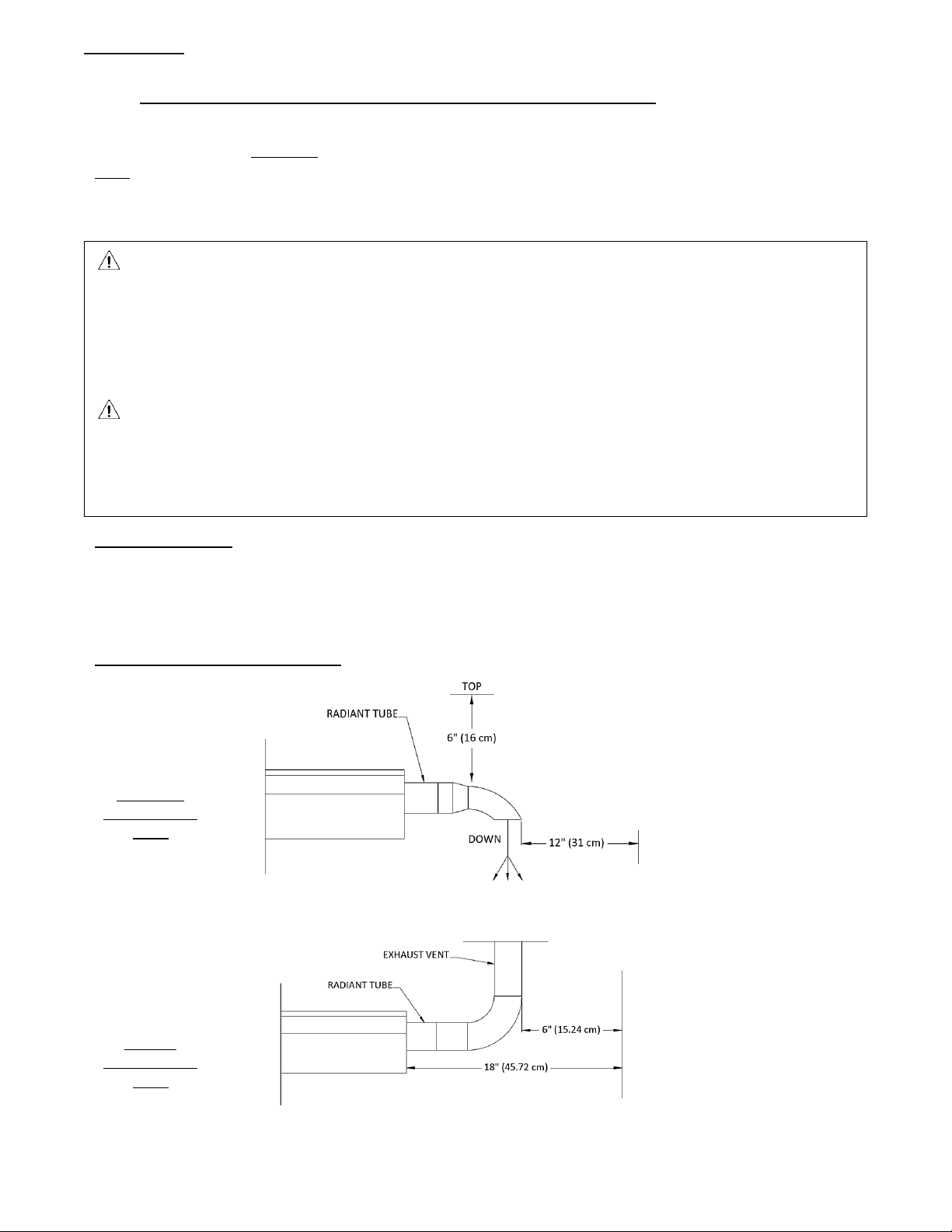
HORIZONTAL VENTING – SINGLE UNIT: For horizontal, sidewall venting a single unit, use 4" (10.16 cm)
“B-Vent” equal to DuraVent PIN# 4GV36 in combination with a combustible wall thimble, a “B-vent” to
“C-Vent” (single wall) adaptor equal to DuraVent PIN#4GVC, and HIGH WIND VENT TERMINAL equal to
DuraVent PIN# 4GVVTH.

PH-SERIES
25
ALTERNATIVELY, for models PH-40, PH-50, PH-75, installer can use material equal to Calcana 3” x 16
gauge sidewall vent kit PIN#800208, c/w 4” x 3” 16 gauge reducer.
NOTE: MAKE SURE THAT ALL FLUE/EXHAUST JOINTS ARE SEALED. USE ONLY SUITABLE PRODUCTS EQUAL TO GENERAL ELECTRIC RTU
106 OR PERMATEX FORM A GASKET RED HIGH TEMPERATURE SILICONE ADHESIVE SEALANT. (NOT SUPPLIED)
D
NOTE: VENT PIPE CAN BE TRIMMED IF NEEDED. CUT EXCESS MATERIAL AS REQUIRED. MAINTAIN 6” (16 cm) CLEARANCE TO
COMBUSTIBLES. SEAL ALL JOINTS WITH HIGH TEMPERATURE SILICON (SEE PAGE Error! Bookmark not defined.).
Figure 15. SIDE WALL VENTING, SINGLE UNIT
NOTE: Maximum length is 25 feet including, two (2) 90° elbows, deduct 10’ for every additional 90° elbow and
5’ for every 45° elbow.
PH-SERIES
26
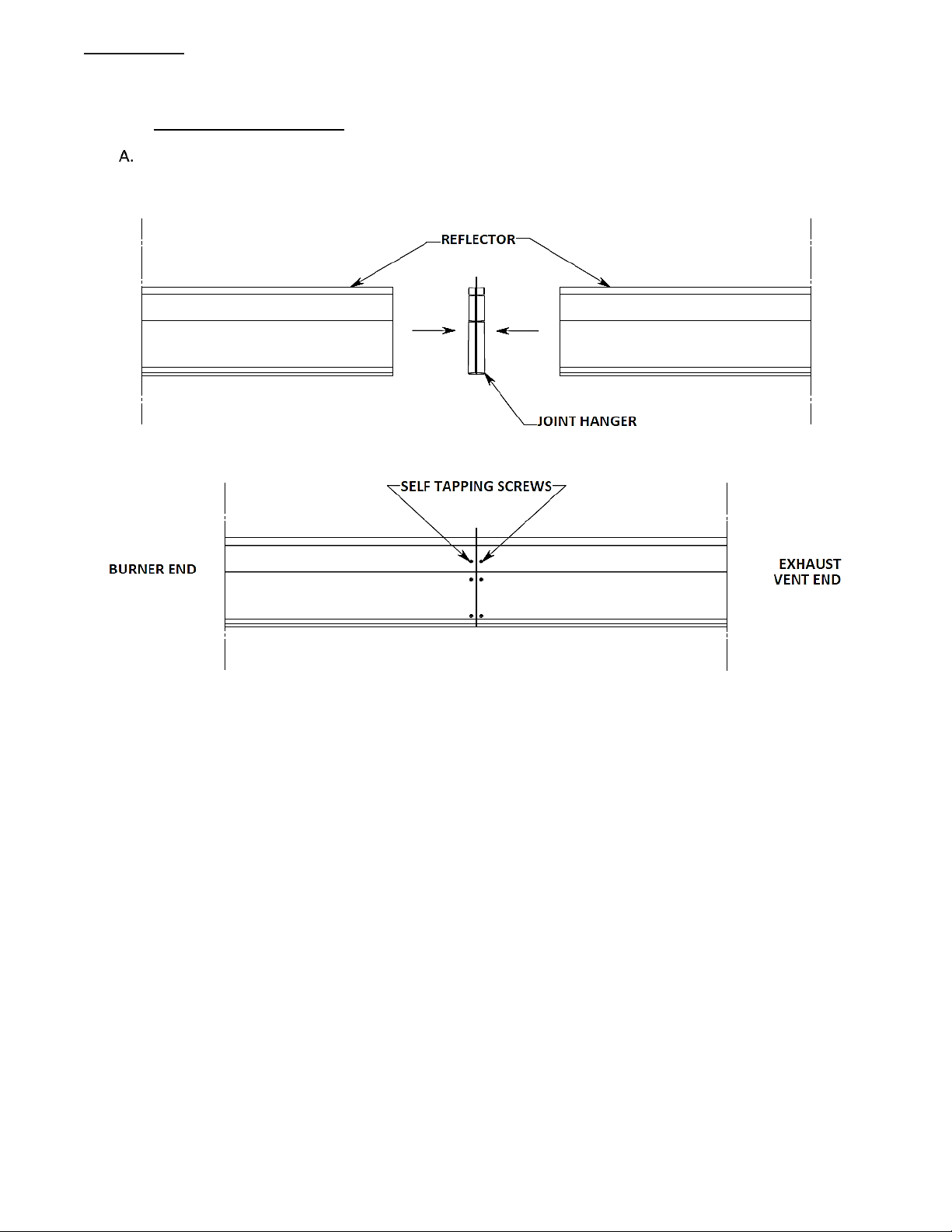
ROOF EXHAUST – VERTICAL VENTING: Use 'B' style chimney.
SIDE VIEW
WARNING: MAKE SURE VENT CAP IS NOT OBSTRUCTED BY SNOW. ADJUST ACCORDINGLY.
Figure 16. VERTICAL VENTING, SINGLE UNIT

PH-SERIES
27
VERTICAL VENTING (CONTINUED) ROOF EXHAUST : TWO OR MORE UNITS - USE 'B' STYLE CHIMNEY.
TWO OR MORE UNITS INTO A COMMON CHIMNEY – SIDE VIEW
NOTE: For venting of two or more heaters into one common chimney, in Canada refer to the Natural Gas and
Propane Installation Code, CSA B149.1 or latest edition and in the USA, the National Fuel Gas Code, ANSI
Z223.1/NFPA 54 or latest edition.
Units that are commonly vented must be controlled by the same line voltage thermostat.
SIDE VIEW
WARNING: MAKE SURE VENT CAP IS NOT OBSTRUCTED BY SNOW. ADJUST ACCORDINGLY.
TOP VIEW
Figure 17. COMMON VERTICAL VENTING, TWO OR MORE UNITS INTO ONE COMMON VENT

PH-SERIES
28
Vent terminal must be installed at a height sufficient to prevent any blockage by snow.
Protect building materials from any degradation that may be caused by flue gases.
Support vent to prevent sagging.
Make sure that all flue joints are sealed. Use only suitable products equal to General Electric RTU106 or
Permatex Form a Gasket Red High Temperature Silicone Adhesive Sealant (not supplied).
For sidewall venting, the heater must not be connected to a separate chimney, but must be installed using
the venting system supplied with the heater.
If condensation in flue is present then flue should be insulated or shortened. Install according to Codes
CAN/CGA-B149.1. In the USA., refer to ANSI Z223.1/NFPA 54 NATIONAL FUEL GAS CODE current edition.
NOTE: Refer to the CAN/CGA-B149.1 code for venting of two or more heaters into one common vertical
chimney. In the USA., refer to ANSI Z223.1/NFPA 54 NATIONAL FUEL GAS CODE current edition.
NOTE: A small amount of condensation may occur from the heater, when it starts the heating cycle. The
condensation will stop once the heater warms up. Make sure all vent

PH-SERIES
29
12.0 GAS PIPING
WARNING: All gas work MUST be performed by qualified/licensed personnel with adequate
training and experience in this field.
WARNING: Use only the type of gas for which the heater is equipped. Using the wrong gas could
create a hazard, resulting in damage, personal injury or death.
In Canada refer to the Natural Gas and Propane Installation Code, CSA B149.1 or latest edition and in the USA,
the National Fuel Gas Code, ANSI Z223.1/NFPA 54 or latest edition.
a) Adequate supply of gas to the heater is required for it to produce the designed amount of heat output.
The gas meter must have a large enough capacity to handle the extra consumption required by the
heater.
b) The gas line must be of an adequate size to deliver the necessary amount of fuel to the unit.
c) If there is any question concerning a) or b) call your local gas company for further assistance.
d) Make sure that all piping is supported properly.
e) All connections must have special sealing compound applied to them.
f) A drip leg must be installed before the heater to prevent contaminating matter interfering with the
operation of the unit.
g) Check piping for leaks via pressure test. Install a 1/8" (3.175 mm) N.P.T plugged tapping immediately
ahead of heater in gas supply. Use this location for test gauge. A soap and water test can be used to verify
location of any possible leak.
WARNING: Do not use an open flame for testing!
WARNING: For high pressure testing, disconnect heater(s) and shut-off cocks and cap off pipe for test.
Failure to do so will damage pressure ratings on the above mentioned equipment and cause a complete
replacement of these parts.
WARNING:
The heater and its individual shutoff valve must be disconnected from the gas supply piping system during
any pressure testing for that system at test pressures in excess of ½ psig.
The heater must be isolated from the gas supply piping system by closing its individual manual shutoff valve
during any pressure testing of the gas supply piping system at test pressures equal to or less than ½ psig.
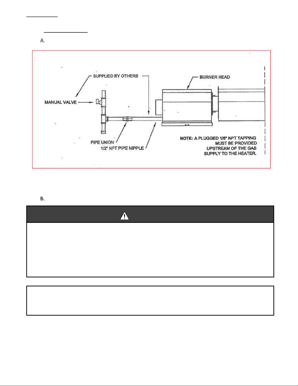
Refer to pages 30 & 31 for gas connection to heater.
PH-SERIES
30
13.0 GAS CONNECTION
HARD PIPE
Figure 18. HARD PIPE INSTALLATION
FLEX CONNECTOR
WARNING:
FIRE AND/OR EXPLOSION HAZARD
Can cause properly damage, severe injury or death.
With each firing cycle, the radiant pipe will expand and contract which can cause the burner head to
move horizontally with reference to the gas supply line.
If the gas connection Is not Installed In strict accordance as shown in Figure 19, a gas leak can occur
resulting in an extreme unsafe condition.
"Certified connectors are recommended to be installed as shown, (Figure 19, page 31) in one plane, and
without sharp bends, kinks, or twists. The gas take off must be parallel to the burner gas inlet connection. "
(CSA)

PH-SERIES
31
CORRECT POSITIONS
INCORRECT POSITIONS
WARNING:
CONNECTOR MUST BE INSTALLED AS PER THE CONFIGURATION ILLUSTRATED ABOVE.
USE ONLY THE 36" (90 cm) CONNECTOR OF ½" (1.27 cm) NOMINAL ID FOR LENGTHS FROM 10' (3m) TO 70' (21.3
m) AND A 36" (90 cm) CONNECTOR OF ¾" (1.905 cm) NOMINAL ID FOR LENGTHS GREATER THAN 70' (21.3m).
IN CANADA: "A radiant tube-type infrared heater shall only be connected with a Type 1 hose connector that is (a)
certified as being in compliance with the Standard for Elastomeric Composite Hose and Hose couplings for
Conducting Propane and Natural Gas, CAN/CGA 8.1 and (b) of a length of 36 +/- 6" (90 +/-15 cm)."
IN USA: Flexible Metallic connectors must be certified for use on a radiant tube-type infrared heater as per the
Standard tor Connectors for Gas Appliances, ANSI Z21.24/CSA 6.10.
Connector is available from manufacturer.
Figure 19. GAS LINE CONNECTION WITH CERTIFIED FLEXIBLE GAS CONNECTION
PH-SERIES
32
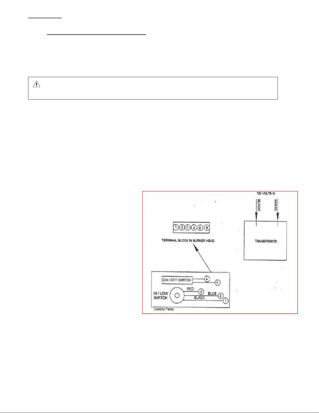
14.0 ELECTRICAL CONNECTION 120 VOLTS
Refer to rating plate on heater for electrical specifications.
Supply adequate grounded electrical power supply to heater via watertight, outdoor rated electrical wiring.
Fasten ground wire to grounding lug on frame of burner head and connect 120 volts to the black and white
pigtail wires from the transformer.
WARNING: DO NOT operate heater until it has been thoroughly installed, inspected and is ready
for initial fire-up.
NOTE: All connections and wiring must be made in accordance with CSA C22.1 CANADIAN ELECTRICAL CODE
PART 1 as well as/or local codes, conditions and authorities. Refer to wiring diagrams on pages 23. In the
USA refer to NATIONAL ELECTRIC CODE ANSI/NFPA 70-1987 or most current edition.
NOTE: If any of the original wire supplied with the unit must be replaced do so only with material having at
least 105 degrees centigrade temperature rating.
The heater, when installed, must be electrically grounded in accordance with local codes or, in the absence or
local codes, with ANSI/NFPA 70.
DO NOT use an extension cord as the electrical source for the heater.
Figure 20. ELECTRICAL CONNECTIONS 120 VOLT
REMOTE CONTROL PANEL
(Low voltage connection)
Locate low voltage controller in convenient location.
Connect multi-strand, low voltage wires to panel.
Secure wiring accordingly and make final connection
inside heater burner box compartment making sure
that the correct number on the terminal strip matches
identically with the color wires on the Hl/Lo switch: The
terminals for the on/off switch, 3 and 4, are not
location specific but must be wired only to 3 and 4 in
the burner head.
ONLY USE APPROVED OUTDOOR WIRE.
Use 18 gauge for distances up to 50' and 16 for
distances greater than 50 feet.
MODELS PH-40, 50 & 75 ONLY:
THERMOSTAT CONNECTION:
USE THERMOSTAT EQUAL TO: HONEY WELL LINE
VOLTAGE MODEL T4098A or T410A. INSTALLED
SUCH THAT THE THERMOSTAT CONTROLS THE
VOLTAGE BEING SUPPLIED TO THE UNIT.

PH-SERIES
33
14.1 120 VOLT WIRING DIAGRAM
MODELS PH-40, 50, 75, 80, 100 and 125 ONLY: THERMOSTAT CONNECTION:
USE THERMOSTAT EQUAL TO: HONEY WELL LINE VOLTAGE MODEL T4098A or T410A. INSTALLED SUCH THAT THE THERMOSTAT
CONTROLS THE VOLTAGE BEING SUPPLIED TO THE UNIT.
Figure 21. WIRING DIAGRAM 120 VOLT
NOTE: If any of the original wire supplied with the unit must be replaced do so only with material having at
least 105 degrees centigrade temperature rating.

PH-SERIES
34
15.0 ELECTRICAL CONNECTION 24 VOLT (ALTERNATE POWER SUPPLY)
1) Locate 24 VAC volt transformer near 120 volt source.
2) Supply wire from transformer to heater must have adequate capacity and insulation temperature
ratings for total connected load. Use 18 gauge wire from transformer to heater for distances up to
50 feet. For distances greater than 50 feet use 16 gauge.
3) If any of the original wire supplied with the unit must be replaced do so only with material having at
least 105 degrees centigrade temperature rating.
4) All connections and wiring must be made in accordance with CSA C22.1 CANADIAN ELECTRICAL CODE
PART 1 as well as/or local codes, conditions and authorities. Refer to wiring diagrams on pages 23. In
the USA refer to NATIONAL ELECTRIC CODE ANSI/NFPA 70-1987 or most current edition.
WARNING: DO NOT operate heater until it has been thoroughly installed, inspected and is ready
for initial fire-up.
Figure 22. ELECTRICAL CONNECTIONS 24 VOLT
REMOTE CONTROL PANEL
(Low voltage connection)
Locate low voltage controller in convenient location.
Connect multi-strand, low voltage wires to panel.
Secure wiring accordingly and make final connection
inside heater burner box compartment making sure
that the correct number on the terminal strip matches
identically with the color wires on the Hl/Lo switch: The
terminals for the on/off switch, 3 and 4, are not
location specific but must be wired only to 3 and 4 in
the burner head.
ONLY USE APPROVED OUTDOOR WIRE.
Use 18 gauge for distances up to 50' and 16 for
distances greater than 50 feet.
24 VAC POWER SUPPLY
Connect to terminal leads #4 and #6 inside burner box.
MODELS PH-40, 50, 75, 80, 100, 125
ONLY: THERMOSTAT CONNECTION:
USE THERMOSTAT EQUAL TO: HONEY WELL LINE
VOLTAGE MODEL T4098A or T410A. INSTALLED
SUCH THAT THE THERMOSTAT CONTROLS THE
VOLTAGE BEING SUPPLIED TO THE UNIT.

PH-SERIES
35
15.1 24 VOLT WIRING DIAGRAM
MODELS PH-40, 50, 75, 80, 100, and 125 ONLY: THERMOSTAT CONNECTION:
USE THERMOSTAT EQUAL TO: HONEY WELL LINE VOLTAGE MODEL T4098A or T410A. INSTALLED SUCH THAT THE THERMOSTAT
CONTROLS THE VOLTAGE BEING SUPPLIED TO THE UNIT.
Figure 23. WIRING DIAGRAM 24 VOLT
NOTE: If any of the original wire supplied with the unit must be replaced do so only with material having at
least 105 degrees centigrade temperature rating.

PH-SERIES
36
16.0 INITIAL START-UP
WARNING:
DO NOT ATTEMPT TO IGNITE HEATER BY HAND!!
IMPORTANT NOTICE: This heater is not to be used as a construction heater to supply heat to an
unfinished building during the finishing phases of Construction. This practice exposes the unit to an
abnormally corrosive atmosphere from sources such as paint, varnish and adhesives, which can lead
to premature radiant tube exchanger or vent failure. The practice also allows foreign materials such as
sawdust or sheet rock dust to enter the combustion blower, burner, heat exchanger and vent system,
resulting in shorter life of the unit.
Use of the heater as a construction heater will void the warranty.
Procedure:
a) Make sure gas is turned on.
b) Check for any possible blockages in combustion air intake and exhaust areas of unit.
c) Make sure all options are attached securely.
d) Make sure electricity is on to unit.
e) Turn control on/off switch to on.
f) Check the flame port to see flame has established,
g) If flame is not established, turn on/off switch to off for 5 seconds then turn back up or interrupt
electrical supply to unit for 5 seconds, and allow unit to try again.
h) Verify that the manifold pressure (outlet pressure tap) on the gas valve is the same pressure as
stated on the rating plate of the unit. Use a manometer that measures inches of water column for
this procedure. If adjustment is required, remove the cap-screw from the pressure regulator housing.
Adjust the pressure regulator adjusting screw according to instruction on page 25. Replace capscrew. After measurement has been taken, replace pipe plug in outlet pressure tap. Check for leaks.
(see pages 3, 4 & 37)
i) Verify gas input rate. (see page 37)
NOTE: Oil smoke might appear off of exchanger tube after it heats up for initial firing. Do not be alarmed. The
smoke is just a small amount of oil on the surface of the tube from manufacturing. If smoke is excessive, open
door and 'air out' the building until smoke is removed.
NOTE: Heater will have a higher heat output by the burner head as compared to the exhaust end. This is
normal.
NOTE: A small amount of condensation may occur from the heater when it starts the heating cycle. The
condensation will stop once the heater warms up.

PH-SERIES
37
Figure 24. GAS VALVE
16.1 SETTING MANIFOLD PRESSURE
MANIFOLD PRESSURE REGULATOR ADJUSTMENT and PRESSURE VERIFICATION PROCEDURE:
TOOLS REQUIRED
-Small Flat Blade Screw Driver
-2 mm (millimeter) allen wrench
-3 mm (millimeter) allen wrench
-Manometer that measures inches of water column (“ W.C.)
-Volt Meter capable of reading AC and DC voltage in a range of 0 to at least 30 volts
INITIAL STEPS:
1) The installer must verify that the heater being installed is of the correct fuel type for the
available fuel that is supplied for this installation. This includes any high altitude correction that
may be applicable for your installation. Confirm site has adequate fuel supply to operate all gas fired
appliances, including this/these heater(s), at their maximum rated capacity simultaneously (at the same
time). Make sure gas lines and pressure regulators are of a capacity to deliver the correct line pressure
within the specified range for your fuel type (5” to 14” w.c. for natural gas and 12” to 14” w.c. for
propane or Propane fuel) to the heater’s gas line inlet connection, with all gas fired appliances on site
operating at the same time. If you are unable to achieve the stated line pressures during operation, you
will not be able to verify and/or adjust the gas manifold pressure setting on this heater, and the heater
will not operate correctly. If fuel pressure is too low, the heater will not have enough fuel to achieve its
maximum heat level. Alternatively, if the fuel line pressure is too high, the valve can be damaged.
2) Make sure all gas-fired appliances on site, other than this heater, are on and operating at the same time.
Otherwise, an inaccurate reading of manifold pressure may occur.
3) Make sure this heater is not operating and is turned off when you start this procedure.
WARNING
INSTALLER MUST VERIFY AND ADJUST, IF NECESSARY, THE MANIFOLD OPERATING PRESSURE OF THIS HEATER
ACCORDING TO THE INSTALLATION MANUAL AND RATING PLATE OF THIS HEATER.
FAILURE TO DO SO WILL VOID ALL WARRANTIES AND MAY CAUSE DAMAGE, INJURY AND/OR DEATH.
IF YOU HAVE ANY QUESTIONS CONCERNING THESE INSTRUCTIONS, CALL CALCANA AT 800-778-6729 BEFORE YOU VERIFY
AND/OR ADJUST THE MANIFOLD FUEL PRESSURE ON THE HEATER. No one should work on or install this heater unless
they are a licensed/qualified and insured contractor trained in the appropriate trade or technical fields
(Gasfitting-HVAC-Electrician) related to the installation and/or service of this heater.
Person(s) who service and/or install this unit accept full liability and responsibility for its operation.
PH-SERIES
38
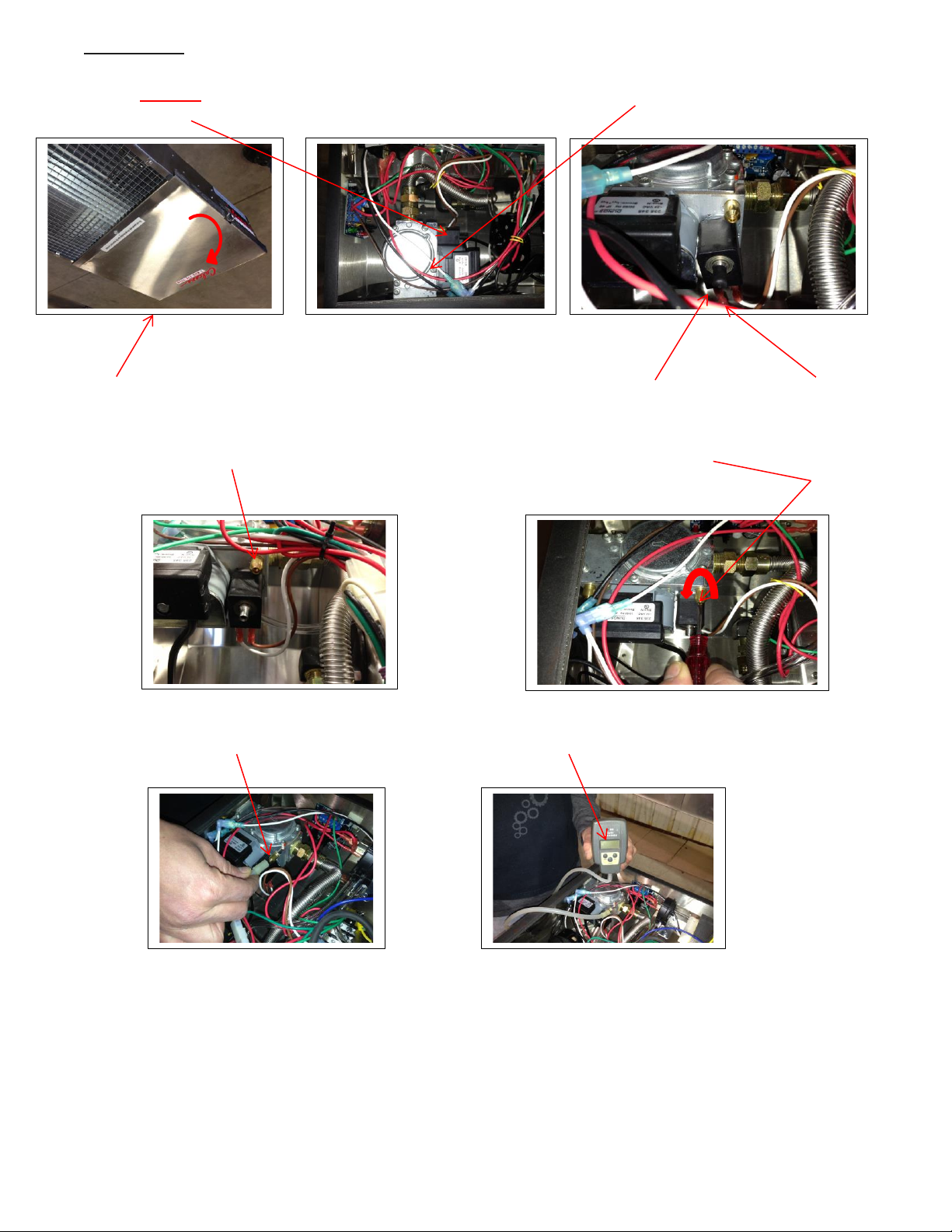
4) START BY opening the service door and identifying the location of the gas valve and the modulator.
Remove the black plastic cap from the adjustment tower.
Service Door Black Plastic Cap Adjustment Tower
1of 3
5) Locate manifold pressure tap. Open the manifold pressure tap by using a small flathead screwdriver to
turn the screw inside the brass fitting counterclockwise 3 turns. DO NOT REMOVE THIS SCREW.
6) Connect a manometer that registers pressure in inches of water column (“W.C.) to the manifold pressure
tap.

PH-SERIES
39
FOR LOW PRESSURE VERIFICATION and/or ADJUSTMENT:
CAUTION: Always adjust low pressure setting first since the low setting will affect the high setting.
7) Remove the electrical connection from the modulator. (Brown and White Wires)
8) Start the heater and take a pressure reading. The manifold pressure required on the low setting for
natural gas is 1.25 “W.C. For liquefied petroleum gas, the manifold pressure should be 5.25” W.C. on low.
The manifold pressure setting information is also contained on the rating plate which is affixed to the side
of the heater near where the service lid is located.
9) If adjustment is needed, insert a 3mm allen wrench into the adjustment tower and turn clockwise to
lower pressure and counterclockwise to increase pressure.
2 of 3
10) Once proper pressure is confirmed, turn off the heater, and go to step 11) for high pressure verification
and/or adjustment instructions.
FOR HIGH PRESSURE VERIFICATION and/or ADJUSTMENT:
11) Rotate the modulator control knob on the control panel to high. Connect electrical meter to the
modulator control wires. Operate heater by turning it on. Voltage output should be between 24 to 28
volts D.C. current. If voltage is correct, turn off heater and connect the electrical supply wires to the
terminals on the modulator. If voltage is incorrect, determine cause for deficient voltage and repair
before you continue.

PH-SERIES
40
12) Start heater and take a pressure reading. For natural gas, manifold pressure should be 3.5 “ W.C. on high.
For liquefied petroleum gas, manifold pressure should be 10.5” W.C. on high.
13) If adjustment is needed, insert a 2mm allen wrench into the adjustment tower and turn clockwise to
lower pressure and counterclockwise to increase pressure.
FINAL STEPS:
14) Once proper pressure is confirmed, turn off the heater, remove the manometer and use a small flathead
screwdriver to turn screw inside brass fitting clockwise until tight.
DO NOT OVER TIGHTEN.
15) Replace the black plastic cap on 16) Close the service lid and replace the self-
the adjustment tower. tapping screw that secures the service lid.
PH-SERIES
41
17.0 GAS INPUT RATE
WARNING:
Natural gas heating values can vary widely. It is the responsibility of the Installer to make sure that the input
rate to the heater as installed does not exceed the nameplate rating of the heater. Failure to do so can cause
radiant tube failure, resulting in injury or death.
The maximum BTUH input capacity for each model is shown on the heater's rating plate and in the specification
table. This input must not be exceeded.
The input shown may be used in geographic area where the elevation is from 0 to 4,500 feet (1372m) above
sea level (Canada only) in accordance with CGA 2.17-M91 (R2003), no change required to main orifice. For
installations above 4,500 (1372 m) refer to Natural Gas and Propane Installation Code, CSA B149.1 or latest
edition, or contact the factory. In the USA: For installations above 2000 feet (610 m), the appliance shall be derated 4 percent (%) for each 1000 feet (305 m) of elevation above sea level. The Btu/hr input depends on the
calorific heating value of the gas, orifice size, and manifold pressure. Orifice sizes are based upon values of
1000 Btu/hr/cu. ft (.028316 cubic meter) and 2500 Btu/hr/cu. ft. (.028316 cubic meter) for L.P.G. (propane).
WARNING:
NEVER ATTEMPT TO MODIFY THIS HEATER - FIRE, EXPLOSION, OR ASPHYXIATION MAY RESULT. If
malfunction is apparent, contact qualified service agency and or gas utility for assistance.
How to Determine Gas Input Rate:
Where gas is metered, the input rate may be determined by the following method, Contact the gas supplier,
Public Utility Company or Propane gas distributor to obtain the calorific gas value of the gas being used. When
checking the gas input rate, any other gas burning appliances connected to the same meter must be completely
off. The heater should be allowed to operate for 5 minutes before attempting to check the gas input rate.
To check flow rate, observe the one cubic foot dial on the gas meter and determine the number of seconds
required for the dial hand to complete one revolution (seconds to flow one cubic foot).
To determine the number of seconds per cubic foot that is necessary to achieve the correct input rate, use the
following formula:
GAS VALUE X 3600 / DESIRED INPUT = SECONDS NEEDED
Example: 1000 BTU gas, heater input 100,000 BTUH
Seconds for one cubic foot = 1000 X 3600 /100,000 = 36 seconds
If when clocking the meter, the one cubic foot dial makes a complete revolution in less time than was calculated
that it should be de-rated. It if takes more time for the meter to make one revolution than was calculated, the
unit is under-fired.
The orifice size must be changed to correct an over-fired or under-fired condition. If it is determined that
different orifices are needed, please contact your distributor for assistance in selecting the correct
replacement.

PH-SERIES
42
18.0 SEQUENCE OPERATION
18.1 DESCRIPTION OF 3-TRY DIRECT SPARK IGNITION SYSTEM:
The TRITON 2461D is a 24 VAC Microprocessor Based Direct Spark Ignition Control designed for use in all types
of heating applications such as gas furnaces, boilers, water heaters and other similar appliances: The control
utilizes a microprocessor to continually and safely monitor, analyze and control the proper operation of the
gas burner. Value added features such as: combustion blower control, LED diagnostics, automatic one hour
reset, and flame current test pins highlight the controls benefits.
18.2 OPERATION:
POWER UP/STANDBY
• Upon applying power (24 volts) to 24 VAC/R, the control will reset, perform a self-check routine,
initiate fulltime flame sensing, flash the diagnostic LED for up to four seconds, and enter the
thermostat scan state.
HEAT MODE
• When a call for heat is received from the thermostat supplying 24 volts to TH/W, the control will
check the pressure switch for normally open contacts. The combustion blower is then energized and
once the pressure switch contacts close, a pre-purge delay begins. Following the pre-purge period
the gas valve is energized and sparks commence for the trial for ignition period.
• When flame is detected during the trial for ignition, sparks are shut off immediately and the gas
valve and combustion blower remains energized. The thermostat, pressure switch, and main burner
flame are constantly monitored to assure the system continues to operate properly. When the
thermostat is satisfied and the demand for heat ends, the main valve is de-energized immediately,
the control senses the loss of flame signal and de-energizes the combustion blower.
FLAME FAILURE - RE-IGNITION
• If the established flame signal is lost while the burner is operating, the control will respond within
0.8 seconds. The HV spark will be energized for a trial for ignition period in an attempt to re-light
the burner. If the burner does not light, the control will make two more attempts to re-light the
burner. If the burner does not re-light, the control will go into lockout and flash the LED 3-times. If
flame is re-established, normal operation resumes.
PH-SERIES
43
19.0 TROUBLESHOOTING
NO POWER TO HEATER
CAUTION: Prior to performing any service or maintenance work on the unit:
a) disconnect the electrical supply
b) shut off gas to supply unit
c) make sure unit has cooled down before opening service panel
Warning:
Only allow qualified, licensed, service people trained to service gas fired heating equipment to perform any
repairs on this unit. All replacement parts MUST originate from the manufacturer of this heater in order not
to void CGA/AGA certification.
Safety devices are not allowed to be rendered inoperative and left unattended. Failure to do any of the
above can cause property damage, injury or death.
INITIAL ELECTRICAL CHECKS
a) Make sure thermostat is calling for heat.
b) Make sure electrical connection is secure.
c) Check electrical supply for blown fuse or breaker.
d) Test for power to burner head.
e) Check wiring to components. Refer to wiring diagrams on pages 33 to 32. Also refer to legend
below; this legend is located on the control module.
TERMINAL DESIGNATIONS
S1
NOT USED
GND
SYSTEM GROUND (GREEN)
V2
VALVE GROUND (BROWN)
R
NOT USED
L1
120/240 VAC INPUT (HOT) (BLACK)
IND
INDUCER BLOWER OUTPUT (BLACK)
V1
VALVE POWER (WHITE)
PSW
PRESSURE SWITCH INPUT (RED)
W
THERMOSTAT INPUT (RED)
CAUTION: Label all wires prior to disconnection when servicing controls. Wiring errors can cause improper and
dangerous operation. A functional checkout of a replacement control is recommended. Verify proper operation
after servicing.
Attention. Au moment de I’ entretien commandes, étiquetez tous les fils avant Ie débranchement. D’erreurs de
câblage peuvent entraîner un fonctionnement inadéquat et dangereux. S’assurer que I’ appareil fonctionne
adéquatement une fois I’ entretien termine.

PH-SERIES
44
INITIAL GAS CHECKS
a) Make sure manual valve is turned on.
b) Make sure gas valve knob is turned on.
c) Check for gas supply and proper pressure to valve.
d) Check wires and make sure that they and their connections are in good condition.
e) Check for power to valve.
f) If no power, check control board. (see page 45)
ELECTRICITY AND GAS TO HEATER, BUT STILL INOPERATIVE
If after confirming that adequate gas and electricity are present and unit still does not operate, review
the symptoms below. After the symptom has been identified, refer to the corresponding cause/cure,
Review CHECK CONTROL BOARD section, and finalize troubleshooting procedure.
Symptom
Cause/Cure
1. Dead
A) Mis-wired
B) Transformer bad
C) Fuse/circuit breaker bad
D) Bad control (check LED for steady on)
2. Thermostat on - No Blower Output
A) Mis-wired (check PSW terminal voltage)
B) Bad thermostat - Do voltage @terminal W
C) Bad control (check LED for steady on)
3. Pressure Switch input okay but no
Trial for Ignition after purge delay
A) Mis-wired (check PSW terminal voltage)
B) Flame sense problem (existing flame-check LED-2
Flashes)
C) Bad control (check voltage between L1 & IND)
4. Valve on, no spark
A) Shorted electrode
B) Open HV cable
C) Bad Control
5. Spark on, no valve
A) Valve coil open
B) Open valve wire
C) Bad control (check voltage between V1 &V2)
6. Flame okay during TFI, no flame
sense (after TFI)
A) Bad electrode
B) Bad S1 or HV wire
C) Poor ground at burner
D) Poor flame (check flame current)
NOTE: TFI = Trial For Ignition

PH-SERIES
45
CHECK CONTROL BOARD
Open access door and view the diagnostic red LED, located on the grey direct spark ignition module.
FAULT CONDITIONS
Error Mode
LED Indication
Internal Control Failure
Steady On
Air Flow Fault
1 flash
Flame with No Call for Heat
2 flashes
Ignition Lock Out
3 flashes
The LED will flash on for ¼ second, then off for ¼ second during a fault condition. The pause between fault
codes is 3-seconds.
INTERNAL CONTROL FAULT
• If power supply cycles are fluctuating beyond 50/60 cycles such as with an un-stabilized power
supply from a generator, unit will not operate. If the circuit board is faulty the unit will not operate.
AIRFLOW FAULT - LOCK OUT (COMBUSTION AIR FLOW PROBLEMS)
• Combustion airflow is continually monitored during an ignition sequence by the airflow switch
(PSW). If during the initial call for heat the pressure switch contacts are in the closed position for 30seconds without an output to the Combustion Blower, an airflow fault will be declared and the
control will remain in this mode with the combustion blower off.
• If the airflow switch remains open for more than 30-seconds after the combustion blower output
(L1 & IND) is energized, an airflow fault will be declared and the control will stay in this mode with
the combustion blower off.
• If the airflow signal is lost while the burner is firing, the control will immediately de-energize the gas
valve and the combustion blower will remain on. If the call for heat remains, the control will wait for
proper airflow to return. If proper airflow air is not detected after 30-seconds an airflow fault signal
will be declared.
Proceed as follows to verify reason for airflow lockout:
1. Check air intake and exhaust for blockage. Remove any blockage.
2. Check combustion air blower for dirt. Clean and/or replace as necessary.
3. If there is no blockage, disconnect fresh air intake at burner head (if equipped). Retry for ignition. If
unit does ignite, check to verify that duct size to unit is of proper size and length and that there is
no blockage. Replace ducting as necessary to reduce amount of air restriction to unit.

PH-SERIES
46
FLAME WITH NO CALL FOR HEAT (FLAME FAULT)
• If at any time the main valve fails to close completely and maintains a flame, the full time flame
sense circuit will detect it and energize the combustion blower. Should the main valve later close off
completely removing the flame signal, the combustion blower will power off.
IGNITION LOCK OUT (FAILURE TO LIGHT)
• FENWAL DSI Module will attempt three ignition trials before going into lockout. The valve relay will
be de-energized immediately, and the combustion blower will be turned off.
• Recovery from lockout requires a manual reset by either resetting the thermostat or removing 24
volts, or removing the electrical power supply for a period of 5-seconds.
• If the thermostat is still calling for heat after one hour, the control will automatically reset and
attempt to ignite the burner again.
If unit still does not operate, proceed as follows:
• Check flame sensor current. (see below)
• Check electrode for cracks and proper location, (see page 47)
FLAME SENSOR CURRENT CHECK
SERVICE CHECKS
Flame current is the current which
passes through the flame from the
sensor to the ground. The minimum
flame current necessary to keep the
system from lockout is .7 micro amps.
To measure flame current, connect
an analog DC micro ammeter to the
FC- FC+ terminals per figure. Meter
should read. 7 uA or higher. If meter
reads below "0" on scale, meter leads
are reversed. Disconnect power and
reconnect meter leads for proper
polarity.
Figure 25. FLAME SENSOR CURRENT CHECK
TRITON 2461D MODULE

PH-SERIES
47
PROPER ELECTRODE LOCATION
Proper location of the electrode assembly is important for optimum system performance. The electrode
assembly should be located so that the tips are inside the flame envelope about ¾” (1.9 cm) to 1” (2.54
cm).
CAUTIONS:
1) Ceramic insulators should not be in or close to the flame
2) Electrode assemblies should not be adjusted or disassembled, Electrodes should have a gap spacing
of .125" (3.175 mm). If this spacing is not correct, the assembly must be replaced.
Electrodes are NOT field adjustable.
3) Exceeding the temperature limits can cause nuisance lockouts and premature electrode failure.
Figure 26. PROPER ELECTRODE LOCATION
PH-SERIES
48
20.0 MAINTENANCE
Maintenance is required once a year. Annually inspect your heater, before the heating season starts. If unit is
in a dusty environment, maintenance will be required more often. If dust conditions are extreme, monthly or
weekly maintenance may be required.
WARNING:
Disconnect electrical supply to heater and shutoff gas prior to inspection.
CHECK COMBUSTION AIR INTAKE FOR BLOCKAGE.
CHECK EXHAUST TERMINAL FOR BLOCKAGE.
OPEN SERVICE DOOR.
CHECK BLOWER MOTOR AND SCROLL FOR DIRT AND/OR LOCKED ROTOR. REMOVE DIRT WITH
COMPRESSED AIR OR VACUUM CLEANER. IF ROTOR IS LOCKED, REPLACE ASSEMBLY.
IF BURNER NEEDS CLEANING, REMOVE BURNER HEAD FROM TUBE AND USE A COMBINATION OF
COMPRESSED AIR AND/OR A WIRE BRUSH TO REMOVE ANY DEPOSITS OR DEBRIS THAT MAY BE ON THE
ACTUAL BURNER.
MAKE SURE ALL WIRING IS INTACT AND IN GOOD CONDITION.
CHECK ELECTRODE FOR PROPER GAP AND CLEANLINESS. CLEAN OR REPLACE AS NECESSARY.
CHECK IGNITION SYSTEM FOR SPARK. REPLACE AS NECESSARY.
CHECK EXCHANGER TUBE FOR HOLES AND/OR CRACKS, DIRT AND/OR DEPOSITS. CLEAN AND/OR
REPLACE AS NECESSARY.
WASH ANY DIRT OR JUST OFF OF THE UNIT WITH A SOAP AND WATER SOLUTION.
CHECK ANY GAS CONNECTIONS THAT WERE DISCONNECTED DURING MAINTENANCE FOR LEAKS. USE
SOAP AND WATER SOLUTION. DO NOT USE FLAME.
TEST FIRE UNIT BY TURNING CONTROL “ON”. MAKE SURE UNIT IS OPERATING QUIETLY AND
EFFICIENTLY.
PERIODICALLY VISUALLY CHECK BURNER THROUGH VIEW PORT TO CONFIRM PROPER OPERATION.
CHECK ALL COUPLERS FOR TIGHTNESS AND/OR LEAKAGE.
WARNING:
Only allow qualified/licensed service people, trained to service gas fired heating equipment, to perform any
repairs on this unit. All replacement parts MUST originate from the manufacturer of this heater in order not
to void CGA/AGA certification. Safety devices are not allowed to be rendered inoperative.
WARNING:
Improper installation, adjustment, alteration, service or maintenance can cause property damage, injury or
death. Read the installation, operating and maintenance instructions thoroughly before installing or servicing
this equipment.
The heater area must be kept clear and free from combustible materials, gasoline and other flammable
vapors and liquids. The flow of combustion and ventilation air to heater must not be obstructed.

PH-SERIES
49
21.0 PARTS:
21.1 BURNER HEAD AND RELATED PARTS
(Refer to pages 51 & 47 for part number & description)
Figure 27. BURNER HEAD PARTS

PH-SERIES
50
21.2 REFLECTOR AND TUBE PARTS
(Refer to page 51 & 47 for part number & description)
Figure 28. REFLECTOR AND TUBE PARTS

PH-SERIES
51
21.3 PARTS LIST:
(See page 49 & 50 for visual details)
REPLACEMENT BURNER HEADS:
ITEM
PIN
INPUT
FUEL
WEIGHT
1
5120000
PH-40
NG
32 lbs (36 kg)
1
5120001
PH-40
Propane
32 lbs (36 kg)
1
5120002
PH-50
NG
32 lbs (36 kg)
1
5120003
PH-50
Propane
32 lbs (36 kg)
1
5120004
PH-75
NG
32 lbs (36 kg)
1
5120005
PH-75
Propane
32 lbs (36 kg)
BURNER HEAD COMPONENTS:
ITEM
PIN
DESCRIPTION
WEIGHT
2
3010001
Blower Motor Assembly
**
3
1090C1
Indicator Light
**
4
3070401
Air Switch PH - 40
**
4
3070402
Air Switch PH - 50
**
4
3704003
Air Switch PH - 75
**
5
3030021
Direct Spark Ignition Module ( Fenwal)
**
6
3030633
Electrode Assembly
**
7
3020005
Gas Valve Propane
**
7
3020003
Gas Valve NG
**
8
3030026
High Voltage Ignition Wire
**
9
3070025
Terminal Block
**
10
3070016
Transformer
**
11
3110022
View Port - Mica Window
**
12
5040374
Vinyl Hose for Differential Air Proving Switch
**
13
3070321
Wire Harness
**
14
LX1000
Variable Input Control
**
15
590156
Burner Assembly
**
TUBE COMPONENTS:
ITEM
PIN
DESCRIPTION
WEIGHT
16
5170147
Baffle Turbulator
5 lbs (2.3 kg)
17
3170325
Flanged Tube Aluminized PH - 40
30 lbs (13.7 kg)
17
3170327
Flanged Tube Aluminized PH - 50 & 75
30 lbs (13.7 kg)
18
37760
Radiant PH - 75
15 lbs (6.8 kg)
19
37759
Radiant PH - 50
30 lbs (13.7 kg)
20
3170201
Tube Clamp
**
21
715013
PH-40 High Output Tube Assembly
45 lbs (21 kg)
22
715014
PH-75 High Output Tube Assembly
65 lbs (30 kg)
23
3200744
4 x 3 Reducer
5 lbs (2.3 kg)
** UNDER 5 LBS

PH-SERIES
52
REFLECTOR COMPONENTS:
ITEM
PIN
DESCRIPTION
WEIGHT
24
5120034
PH Bulkhead SS
5 lbs (2.3 kg)
25
5120033
PH End Cap SS Exhaust
5 lbs (2.3 kg)
26
5120040
PH - 50 & 75 Hanger Assembly
5 lbs (2.3 kg)
27
5180161
Reflector 5' (1.53m)
10 lbs (4.54 kg)
28
5180162
Reflector 10' (3m)
20 lbs (9.1 kg)
29
5180708
SS Reflector SupportStrap
**
30
5080319
Flange Gasket
**
31
4160152
Decorative Egg Crate Grill
5 lbs (2.3 kg)
32
715001
PH-40 High Output Reflector Assembly
15 lbs (6.8 kg)
33
715007
PH-75 High Output Reflector Assembly
30 lbs (13.7 kg)
** UNDER 5 LBS
PH-SERIES
53
22.0 WARRANTY
Non-Transferable / Limited Warranty - Calcana Heaters
Calcana Industries Ltd. (''the Manufacturer") warrants to the
original owner at the original installation site that the heater
manufactured by the manufacturer (''the Product") will be
free from defects in material and workmanship for one (1)
year from date of shipment from the factory. Calcana further
warrants that the heat exchanger, reflectors, brackets,
burner and burner box will be free from defects in material
and workmanship for three (3) years from the date of
shipment from the factory. If upon examination by the
Manufacturer the Product is shown to have a defect in the
material or workmanship during the warranty period, the
Manufacturer will repair or replace, at its option, that part of
the Product which is shown to be defective. In no event shall
the customer be entitled to consequential, indirect or special
damages of any nature for defective merchandise, and in no
instance may damages include loss of profit. Calcana reserves
the right to inspect the system involved in any claim against
the warranty. The warranty is null and void if any of the
components installed are not original Calcana parts or the
installation does not conform to the supplied installation
manual.
This limited warranty does not apply:
a) If the Product has been subjected to misuse or neglect,
has been accidentally or intentionally damaged, has not
been installed, maintained or operated in accordance
with the furnished written instructions, or has been
altered or modified in any way by an unauthorized
person.
b) To any expenses, including labor or material, incurred
during removal or reinstallations of the Product.
c) To any damage due to corrosion by chemicals, including
halogenated hydrocarbons precipitated in the air.
d) To any workmanship of the Installer of the Product
e) If Product is not paid for in a timely manner and in
accordance with payment terms
f) If Product or any part of it is damaged by any act of
nature including, but not limited to; hurricanes, gales,
tornadoes, wind snow, sleet, hail, rain, flood, fire or any
other similar or dissimilar condition, or by normal wear
and tear, which included marks and/or dents to the
reflector caused by improper transportation or
installation.
g) If Product or any part of it is damaged by vandalism,
improper use, accumulation of weight or heavy loads on
the heater.
h) If Product is damaged due to lack of cleaning or
maintenance, whether routine or otherwise.
The limited warranty is conditional upon:
a) Advising the installing contractor, who will in turn notify the
distributor or Manufacturer.
b) Shipment to the Manufacturer of that part of the Product
thought to be defective. Goods can only be returned with
prior written approval of the Manufacturer. All returns must
be freight prepaid.
c) Determination in the reasonable opinion of the
Manufacturer that there exists a defect in material or
workmanship.
Repair or replacement of any part under the Limited Warranty
shall not extend the duration of the warranty with respect to such
repaired or replaced part beyond the stated warranty period.
All labor during the warranty period is the responsibility of the
installing person or contractor.
This Limited Warranty is in lieu of all other warranties, either
express or implied, and all such other warranties, including
without limitation implied warranties of merchantability and
fitness for a particular purpose, are hereby disclaimed and
excluded from this limited warranty. The warranty cannot be
transferred or assigned by the Customer. All disputes arising from
this warranty are to be governed by the laws of the Province of
Alberta and any action to enforce this warranty must be initiated
in the Province of Alberta. In no event shall the Manufacturer be
liable, in any way for any consequential, special, or incidental
damages of any nature whatsoever, or for any amounts in excess
of the selling price of the Product or any parts thereof found to
be defective. This Limited Warranty gives the original owner of
the Product specific legal rights. You may also have other rights
which may vary by each jurisdiction.
USA
Calcana USA Ltd.
30201 County Road 49
Loxley, AL, 36551
Tel: 251-964-4400
Fax: 251-964-4404
PH-SERIES
54
23.0 CONVERSION KIT FOR VARIABLE INPUT GAS VALVES
The conversion shall be carried out in accordance with the requirements of the provincial/state authorities having
jurisdiction and in accordance with the requirements as follows:
CANADA: Natural Gas and Propane Installation Code, CSA B149.1 or latest edition.
USA: National Fuel Gas Code, ANSI Z223.1/NFPA 54, or latest edition.
WARNING: This conversion kit shall be installed by a qualified service agency in accordance with the
manufacturer's instructions and all applicable codes and requirements of the authority having jurisdiction. If
the information in these instructions is not followed exactly, a fire, explosion or production of carbon monoxide
may result causing property damage, personal injury or loss of life. The qualified service agency is responsible
for the proper installation of this kit. The installation is not proper and complete until the operation of the
converted appliance is checked as specified in the manufacturer's instructions supplied with the kit. The
installer of this conversion kit assumes full responsibility and liability for the installation of this conversion kit.
If you do not understand these instructions or the information contained in the installation manual, DO NOT
INSTALL THIS CONVERSION KIT OR OPERATE THE UNIT ASSOCATED WITH THIS GAS CONVERSION.
DIRECTIONS:
1) Caution the gas supply shall be shut off prior to disconnecting the electrical power, before proceeding with the conversion.
2) Turn off electrical supply to heater
3) Disconnect gas supply line to heater
4) Disconnect electrical supply to heater
5) Disconnect thermostat control wire from heater
6) Remove burner head from reflector assembly being careful to support burner head in such a fashion that it will not fall from
the location overhead where it was installed. Use two people if necessary.
7) Remove service door that provides access to gas valve location
8) Remove igniter assembly.
9) Use deep wall socket to remove orifice spud.
10) Install correct orifice for the fuel that you are converting to. CHECK TWICE TO MAKE SURE. Reference chart below:
11) Locate gas valve and REPLACE WITH THE GAS VALVE IN CONVERSION KIT. Verify you have the correct valve for the fuel type
you want to convert to. CHECK TWICE TO MAKE SURE.
12) Verify Manifold pressure using a manometer. Adjust pressure if necessary. (see valve instructions for details)
Manifold Pressure is: NG: Hi 3.5“ w.c. Lo 1.5” w.c.
LPG: Hi 10.5” w.c. Lo 5.5” w.c.
Leak Test all Fittings Prior to Operation
13) When the conversion is complete, fill out the information as required on the enclosed conversion label.
14) Attach completed label on or near the rating plate
Conversion Chart With Part Numbers and Corresponding Orifice Sizes
MODEL
PIN
FROM
TO
ORIFICE
MODEL
PIN
FROM
TO
ORIFICE
CAL/PH 40
3025025
NG
Propane
#51
CAL/PH 40
3025028
Propane
NG
#32
CAL/PH 50
3025026
NG
Propane
#48
CAL/PH 50
3025029
Propane
NG
3.3mm
CAL/PH 75
3025027
NG
Propane
#42
CAL/PH 75
3025030
Propane
NG
#21
NOTE: CONVERSION KITS COME WITH GAS VALVE CONVERSION SPRING, PREDRILLED ORIFICE AND CONVERSION LABEL.
CONVERSION KITS ARE FOR UNITS RATED FOR THE FOLLOWING LOCATIONS AND ELEVATIONS: CANADA: 0 – 4500 FT (1372 m)
FOR INSTALLATIONS ABOVE THE DESIGNATED ELEVATIONS, CONTACT FACTORY. USA: 0 – 2000 FT (610 m)
Calcana USA Ltd.
30201 Country Road 49
Loxley, AL. 36551
Tel: 251-964-4400

PH-SERIES
55
BURNER AND GAS ORIFICE LOCATION

PH-SERIES
56
24.0 EXAMPLE OF CONVERSION KIT LABEL
TO BE COMPLETED AS PER INSTRUCTIONS IN KIT
This appliance was converted on DAY: _______________
MONTH: ________________YEAR: ___________________
to NG: _____Propane. ______ gas with Kit #
_______________
by: NAME: _______________________________________
COMPANY: ______________________________________
ADDRESS: _______________________________________
CITY/TOWN: __________________ STATE/PRO: ________
TELEPHONE: _____________________________________
Orifice Size: _______ leak Test Performed: Yes: _______
Manifold Pressure: Min____________ Max____________
Input: ___________________ Altitude: _______________
(The name of the individual and organization making this
conversion accepts the responsibility that this conversion
has been properly made and has performed a leak test on
the appliance prior to placing into service.) Locate label in
a conspicuous location on the appliance near rating plate.
================================================
Cet appareil a ete converti au: ______________________
Injecteur: __________________Date: ________________
Pression a la tubulure d'alimertation: ________________
Debit calorifique: _________________________________
PH-SERIES
57
25.0 SAFETY AND OPERATING INSTRUCTIONS
! WARNING: !
Failure to follow these instructions will cause death, personal injury or property damage. Read the
installation, operating and maintenance instructions thoroughly before installing or servicing this
equipment.
SAFETY INSTRUCTIONS
READ BEFORE OPERATING
OPERATING
INSTRUCTIONS
A) This gas heater does not have a pilot. It is
equipped with an Ignition device which
automatically lights the burner. DO NOT try to
light the burner with a match, or flame.
B) BEFORE OPERATING, smell all around the
heater area for gas. Be sure to smell next to
the floor because some gas is heavier than air
and will settle to the floor.
WHAT TO DO IF YOU SMELL GAS
• Do not try to operate heater.
• Do not touch any electric switch; do not
use any phone in your building.
• Immediately call your gas supplier from a
neighbor’s phone. Follow the gas
supplier’s instructions.
• If you cannot reach your gas supplier, call
the fire department.
C) Use only your hand to turn the gas valve
handle. Never use tools. If handle will not turn
by hand, do not try to repair it, call a qualified
service technician. Force or attempted repair
may result in a fire or explosion.
D) Do not use this heater if any part has been
under water. Immediately call a qualified
service technician to inspect the heater and to
replace any part of the control system which
has been under water.
1. STOP! Read the safety Instructions on this
label.
2. Open the manual gas valve in the heater supply
line.
3. Turn on electric power to the heater.
4. Set the thermostat to the desired setting.
5. This heater is equipped with an Ignition device,
which automatically lights burner. Do not try to
light the burner with a match, or flame.
6. If heater will not operate, follow instructions
"To Turn Off Gas To Heater" and call your
service technician or gas supplier.
TO TURN OFF THE
GAS TO HEATER
1. Set the thermostat to the lowest setting.
2. Turn off electric power to the heater if service
is to be performed.
3. Turn off the manual gas valve in the heater
supply line.
4. Wait 5 minutes before attempting to relight
heater.
 Loading...