

Page 1
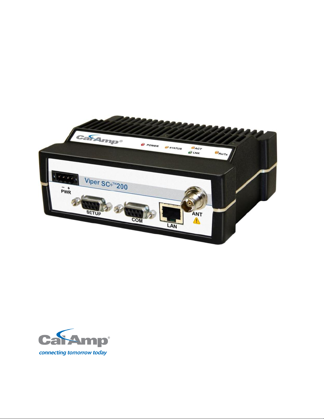
VIPER SC+™
INTELLIGENT IP ROUTERS FOR LICENSED SPECTRUM
User Manual
Viper SC+™ Intelligent IP Routers for Licensed Spectrum
PN 001-5008-000 Rev. C
Revised February 2016
Page 2

REVISION HISTORY
REV
DATE
REVISION DETAILS
0
January 2008
Initial release as 001-5008-000.
1-12
2008-2012
Numerous updates driven by model additions and software changes.
A
December 2013
Added new models, Viper SC™+; all Viper SC™ models become Viper SC+ when upgraded
with new Viper SC+ firmware.
B
February 2015
Added UL warnings. Corrected voltage requirements. Numerous additions and changes
driven by changes/additions to configuration changes.
C
February 2016
Updated Remote Diagnostics page to add PER mode support.
Page 3
Important Notice
When operating at elevated temperature extremes, the surface may exceed +70 Celsius. For user safety, the
Viper should be installed in a restricted access location.
WARNING — EXPLOSION HAZARD, do not connect while circuit is live unless area is known to be nonhazardous.
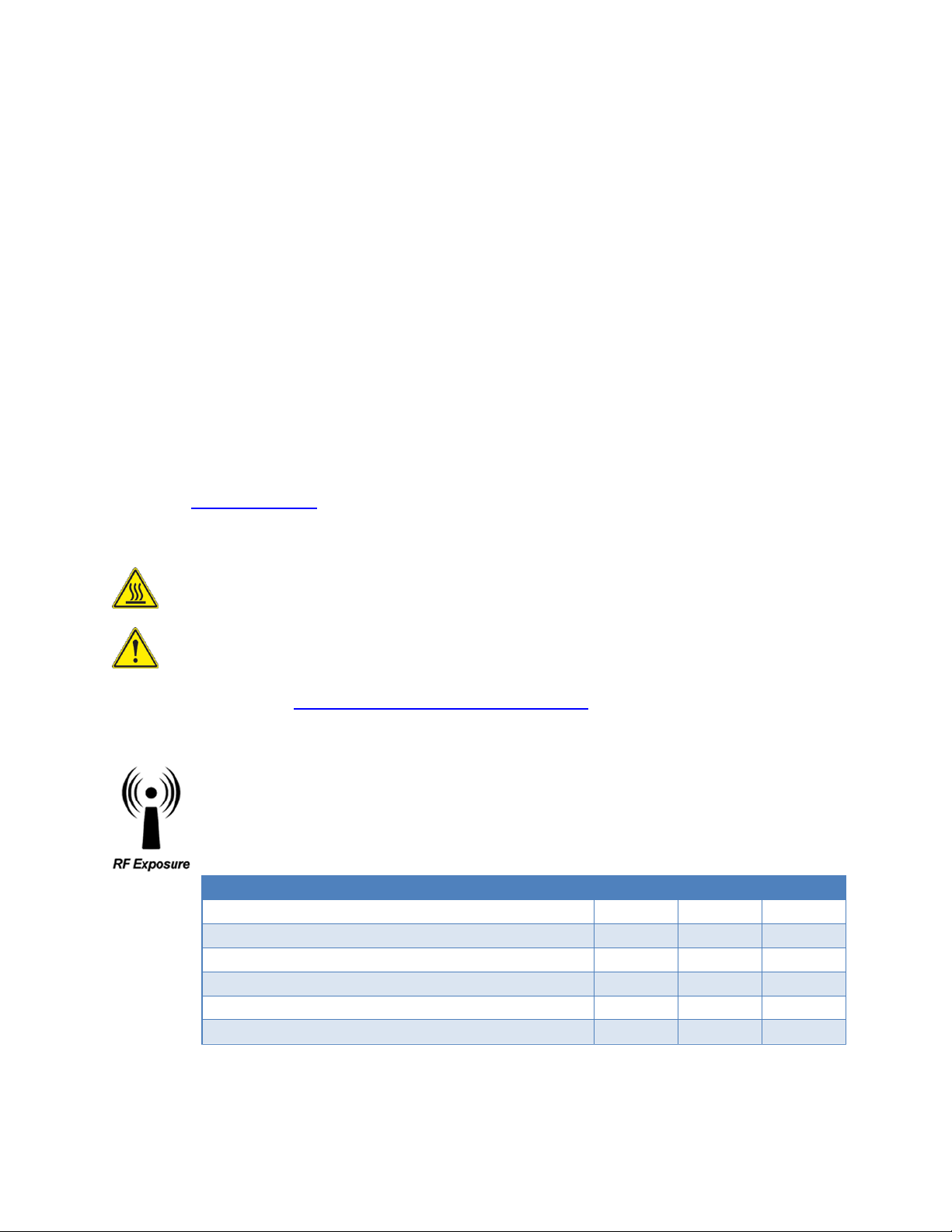
Minimum Safety Distance
Antenna Gain
(cm @max power)
5 dBi
10 dBi
15 dBi
132 MHz (VHF)
123 cm
219 cm
389 cm
215 MHz (UHF)
123 cm
219 cm
389 cm
406.1 MHz
106 cm
188 cm
334 cm
900 MHz (Model/PN 140-5098-304)
66 cm
117 cm
208 cm
900 MHz (Model/PN 140-5098-504)
64 cm
115 cm
202 cm
Because of the nature of wireless communication, transmission and reception of data can never be
guaranteed, Data may be delayed, corrupted (i.e., have errors), or be totally lost. Significant delays or losses
of data are rare when wireless devices such as the Viper SC+™ are used in a normal manner with a wellconstructed network. Viper SC+ should not be used in situations where failure to transmit or receive data
could result in damage of any kind to the user or any other party, including but not limited to personal injury
or death, or loss of property. CalAmp accepts no responsibility for damages of any kind resulting from delays
or errors in data transmitted or received using Viper SC+, or for the failure of Viper SC+ to transmit or
receive such data.
Copyright Notice
© 2010-2016 CalAmp. All rights reserved.
Products offered may contain software which is proprietary to CalAmp. The offer or supply of these
products and services does not include or infer any transfer of ownership. No part of this documentation or
information supplied may be divulged to any third party without the express written consent of CalAmp.
CalAmp reserves the right to update its products, software, or documentation without obligation to notify
any individual or entity. Product updates may result in differences between the information provided in this
manual and the product shipped. For access to the most current product documentation and application
notes, visit www.calamp.com.
UL Listed models only
For more information see APPENDIX D — UL Installation Instructions
RF Exposure Compliance Requirements
Viper SC+ radios are intended for use in the Industrial Monitoring and Control and SCADA
markets. Each Viper SC+ unit must be professionally installed and must ensure a minimum
separation distance listed in the table below between the radiating structure and any person.
An antenna mounted on a pole or tower is the typical installation and in rare instances, a 1/2wave whip antenna is used.
Note: It is the responsibility of the user to guarantee compliance with the FCC MPE regulations when
operating this device in a way other than described above. The installer of this equipment must ensure the
antenna is located or pointed such that it does not emit an RF field in excess of Health Canada limits for the
general population.
Viper SC +™ IP Router for Licensed Spectrum PN 001-5008-000 Rev. C | Page i
Page 4
Viper SC+ uses a low-power radio-frequency transmitter. The concentrated energy from an antenna may
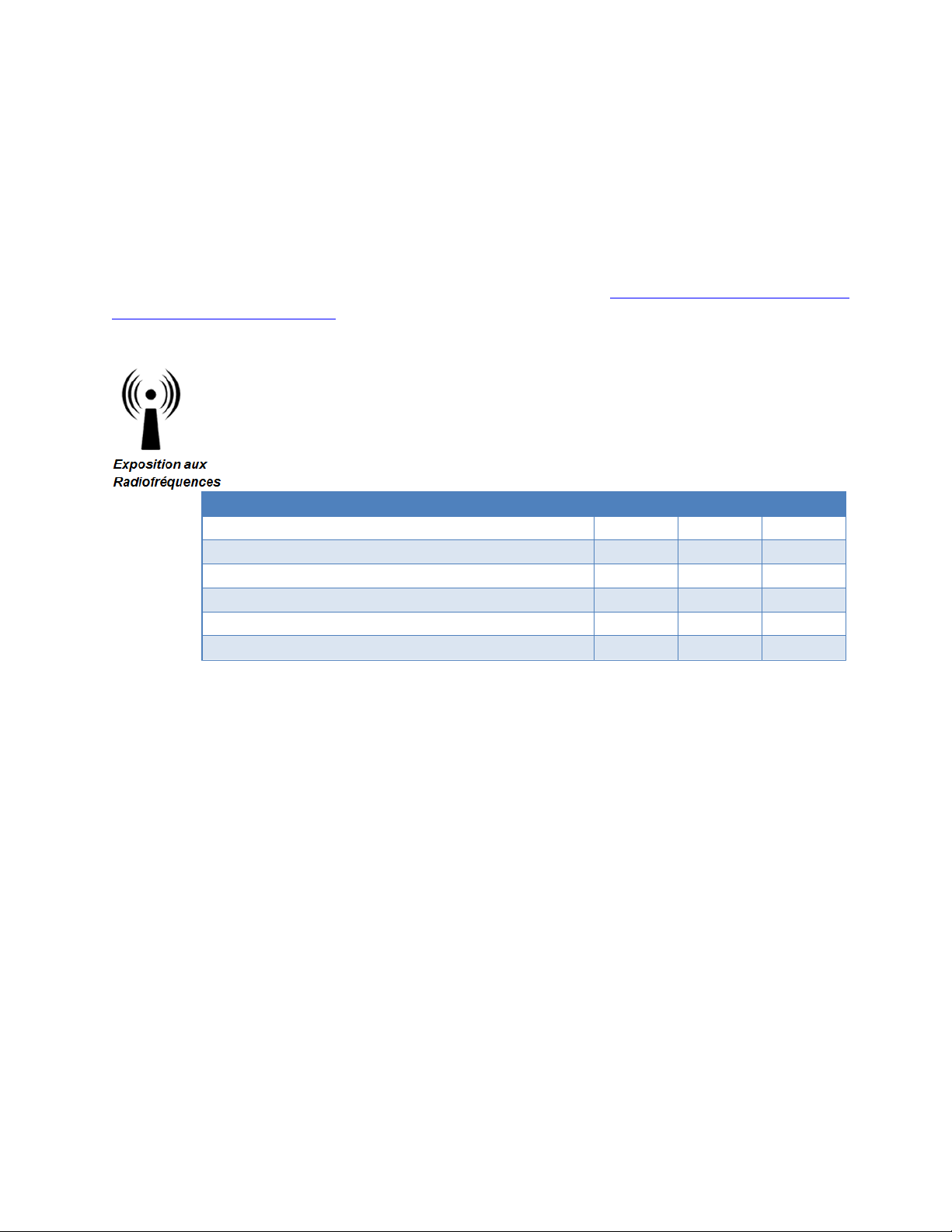
Distance de sécurité minimum
Gain de Antenne
(puissance cm @ max)
5 dBi
10 dBi
15 dBi
132 MHz (VHF)
123 cm
219 cm
389 cm
215 MHz (UHF)
123 cm
219 cm
389 cm
406.1 MHz
106 cm
188 cm
334 cm
900 MHz (Modèle # 140-5098-304)
66 cm
117 cm
208 cm
900 MHz (Modèle # 140-5098-504)
64 cm
115 cm
202 cm
pose a health hazard. People should not be in front of the antenna when the transmitter is operating.
The installer of this equipment must ensure the antenna is located or pointed such that it does not emit an
RF field in excess of Health Canada limits for the general population. Recommended safety guidelines for the
human exposure to radio-frequency electromagnetic energy are contained in the Canadian Safety Code 6
(available from Health Canada), the Federal Communications Commission (FCC) Bulletin 65, and the Council
of the European Union’s Recommendation of 12 July 1999 on the limitation of exposure of the general
public to electromagnetic fields (0 Hz to 300 GHz) (1999/519/EC).
Caution: Before deploying your system, you must read and understand Section 2.5 Selecting Antenna and
Lightning Arrestor combinations.
Exigences de conformité d'exposition aux Radiofréquences
La radio Viper SC+ est destinée à être utilisé dans les marchés contrôles industriels et
SCADA. L'unité Viper SC doit être installée par un professionnel et doit assurer une distance
minimale de séparation entre les sources radiantes et toute personne. Les distances sont
indiquées dans le tableau ci-dessous. L’installation typique est une antenne de type fouet
1/2-longueur d’onde installée sur un poteau ou pylône.
Note: Il est de la responsabilité de l'utilisateur de garantir le respect des règlements MPE de la FCC lorsque
vous utilisez cet appareil d'une façon autre que celle décrite ci-dessus. L’installateur doit s'assurer que
l'antenne est située ou orientée de façon à ne pas émettre un champ RF dépassant les limites de radiations
pour la population générale établies par Santé Canada.
La radio Viper SC+ utilise un émetteur à radiofréquence à faible puissance. L’énergie concentrée d'une
antenne peut poser un risque pour la santé. On ne devrait pas être en face de l'antenne lorsque l'émetteur
est en marche.
Les consignes de sécurité recommandées pour l'exposition humaine à l'énergie électromagnétiques de
radiofréquences sont contenues dans le Code 6 canadien de la sécurité (disponible auprès de Santé Canada),
la Commission Communications Fédéral (FCC) Bulletin 65 et la recommandation du 12 Juillet 1999 sur la
limitation de l'exposition du public aux champs électromagnétiques (de 0 Hz à 300 GHz) (1999/519/CE) du
Conseil de l'Union européenne.
Viper SC +™ IP Router for Licensed Spectrum PN 001-5008-000 Rev. C | Page ii
Page 5

Class A Digital Device Compliance
Note: This equipment has been tested and found to comply with the limits for a Class A digital device,
pursuant to part 15 of the FCC Rules. These limits are designed to provide reasonable protection against
harmful interference when the equipment is operated in a commercial environment. This equipment
generates, uses, and can radiate radio-frequency energy and, if not installed and used in accordance with
the instruction manual, may cause harmful interference to radio communications. Operation of this
equipment in a residential area is likely to cause harmful interference in which case the user will be required
to correct the interference at his or her own expense.
Any changes or modifications not expressly approved by the party responsible for compliance (in the
country where used) could void the user’s authority to operate the equipment.
Viper SC +™ IP Router for Licensed Spectrum PN 001-5008-000 Rev. C | Page iii
Page 6

TA BLE O F CONTENTS
1 Viper SC + Overview ............................................................................................................................. 1
1.1. General Description ............................................................................................................................................... 1
1.2. Operational Characteristics .................................................................................................................................... 1
1.3. Physical Description ............................................................................................................................................... 2
1.3.1. Chassis Dimensions ....................................................................................................................................... 2
1.3.2. LED Panel ...................................................................................................................................................... 2
1.3.3. Front Panel.................................................................................................................................................... 3
1.4. Part Numbers and Availability................................................................................................................................ 6
1.4.1. Viper SC+ Radio ............................................................................................................................................. 6
1.4.2. Fan Kits and Cables ....................................................................................................................................... 8
1.5. Components ........................................................................................................................................................... 9
1.5.1. Basic Unit ...................................................................................................................................................... 9
1.5.2. Two- and Three-Piece Kit Additional Items ................................................................................................ 10
2. Network Architecture And System Planning .................................................................................... 11
2.1. Network Architecture .......................................................................................................................................... 11
2.1.1. Point-to-Point Network .............................................................................................................................. 12
2.1.2. Point-to-Multipoint Network ...................................................................................................................... 12
2.1.3. Report by Exception Configuration ............................................................................................................. 13
2.1.4. Extending the Coverage Area with a Relay Point........................................................................................ 13
2.2. IP Forwarding Modes ........................................................................................................................................... 14
2.2.1. Bridge Mode ............................................................................................................................................... 14
2.2.2. Router Mode ............................................................................................................................................... 16
2.2.3. Viper Router Generator (VRG) Program ..................................................................................................... 19
2.2.4. Multispeed Networking .............................................................................................................................. 19
2.3. Understanding RF Path Requirements ................................................................................................................. 20
2.4. Site Selection and Site Survey .............................................................................................................................. 21
2.4.1. Site Selection .............................................................................................................................................. 21
2.4.2. Site Survey .................................................................................................................................................. 21
2.5. Selecting Antenna and Lightning Arrestor combinations .................................................................................... 21
2.5.1. Lightning Arrestor Overview ....................................................................................................................... 21
2.5.2. Antenna Overview ...................................................................................................................................... 22
2.5.3. The Wrong Combination............................................................................................................................. 22
2.5.4. Good Design Practices ................................................................................................................................ 23
2.6. Selecting Antenna and Feedline........................................................................................................................... 24
2.6.1. Antenna Gain .............................................................................................................................................. 24
2.6.2. Types of Antennas ...................................................................................................................................... 24
2.6.3. Feedline ...................................................................................................................................................... 25
2.6.4. RF Exposure Compliance Requirements ..................................................................................................... 25
Viper SC+™ IP Router for Licensed Spectrum PN 001-5008-000 Rev. C | Page iv
Page 7

2.7. Terrain and Signal Strength .................................................................................................................................. 27
2.8. Radio Interference ............................................................................................................................................... 27
3. Getting Started: Quick Setup and Initial Configuration ................................................................... 28
3.1. Install the Antenna ............................................................................................................................................... 28
3.2. Measure Primary Power ...................................................................................................................................... 28
3.3. Connect the Viper SC+ to Programming PC ......................................................................................................... 29
3.4. LAN Configuration ................................................................................................................................................ 29
3.5. Log In .................................................................................................................................................................... 29
3.6. Introduction to the Viper SC+ Web Interface ...................................................................................................... 30
3.7. Initial Configuration Using the Setup Wizard ....................................................................................................... 31
3.7.1. Setup Wizard Step 1: Station Name and Mode Settings ............................................................................ 32
3.7.2. Setup Wizard Step 2: Network IP Settings .................................................................................................. 33
3.7.3. Setup Wizard Step 3: Radio Setup .............................................................................................................. 34
3.7.4. Setup Wizard Step 4: Encryption ................................................................................................................ 35
3.7.5. Setup Wizard Step 5: Completion and Reset .............................................................................................. 35
4. Viper SC+ Web Interface .................................................................................................................... 36
4.1. Home .................................................................................................................................................................... 37
4.1.1. Unit Status .................................................................................................................................................. 37
4.1.2. RF Status ..................................................................................................................................................... 39
4.1.3. Basic Settings .............................................................................................................................................. 40
4.2. Radio Settings....................................................................................................................................................... 41
4.2.1. RF Settings .................................................................................................................................................. 41
4.2.2. CWID ........................................................................................................................................................... 44
4.2.3. RF Tests ....................................................................................................................................................... 46
4.3. RF Network Settings ............................................................................................................................................. 48
4.3.1. RF Network ................................................................................................................................................. 48
4.3.2. RF Bandwidth Management ....................................................................................................................... 50
4.3.3. Neighbor Table ........................................................................................................................................... 54
4.3.4. Global Settings ............................................................................................................................................ 60
4.3.5. VLAN ........................................................................................................................................................... 61
4.3.6. QoS.............................................................................................................................................................. 65
4.3.7. QoS Statistics .............................................................................................................................................. 69
4.4. LAN Settings ......................................................................................................................................................... 70
4.4.1. LAN Settings ................................................................................................................................................ 70
4.4.2. DHCP ........................................................................................................................................................... 72
4.4.3. SNTP ............................................................................................................................................................ 73
4.4.4. Broadcast Multicast .................................................................................................................................... 75
4.4.5. VLAN ........................................................................................................................................................... 76
4.4.6. Ethernet (PHY) ............................................................................................................................................ 83
4.5. Router .................................................................................................................................................................. 83
4.5.1. Routing Table .............................................................................................................................................. 84
4.5.2. NAT ............................................................................................................................................................. 86
Viper SC +™ IP Router for Licensed Spectrum PN 001-5008-000 Rev. C | Page v
Page 8

4.5.3. VTS .............................................................................................................................................................. 87
4.6. Serial..................................................................................................................................................................... 90
4.6.1. COM Port and Setup Port ........................................................................................................................... 90
4.6.2. VLAN ........................................................................................................................................................... 97
4.6.3. Advanced .................................................................................................................................................. 100
4.7. Security .............................................................................................................................................................. 101
4.7.1. Password ................................................................................................................................................... 101
4.7.2. AES Encryption .......................................................................................................................................... 102
4.7.3. RADIUS ...................................................................................................................................................... 103
4.7.4. VPN ........................................................................................................................................................... 105
4.8. Diagnostics ......................................................................................................................................................... 113
4.8.1. Interface Statistics .................................................................................................................................... 113
4.8.2. Remote Statistics ...................................................................................................................................... 115
4.8.3. SNMP ........................................................................................................................................................ 117
4.8.4. Online Diagnostics .................................................................................................................................... 119
4.8.5. Radio Log .................................................................................................................................................. 123
4.9. Device Maintenance .......................................................................................................................................... 124
4.9.1. Config Control ........................................................................................................................................... 124
4.9.2. Package Control ........................................................................................................................................ 126
4.9.3. Wing Commander ..................................................................................................................................... 126
5. Network Optimization ...................................................................................................................... 130
5.1. Maximizing TCP/IP Throughput ......................................................................................................................... 130
5.2. Maximizing Throughput with a Weak RF Link .................................................................................................... 130
5.2.1. Use Router Mode with RF Acknowledgements Enabled .......................................................................... 130
5.2.2. Reduce RF Network Bit Rate ..................................................................................................................... 130
5.2.3. Use Data Retries ....................................................................................................................................... 131
5.2.4. Use Collision Avoidance ............................................................................................................................ 131
6. Using CalAmp-Provided and Cloned Viper Configurations ............................................................ 132
6.1. Using CalAmp Pre-Provided (“Canned”) Configurations .................................................................................... 132
6.2. Cloning a Viper ................................................................................................................................................... 133
7. Upgrading Firmware ......................................................................................................................... 134
7.1. Firmware Introduction ....................................................................................................................................... 134
7.2. How The Viper Firmware is Upgraded ............................................................................................................... 134
7.2.1. Upgrade the Modem Firmware ................................................................................................................ 134
7.2.2. Upgrade the Radio Firmware .................................................................................................................... 135
APPENDIX A – Abbreviations and Definitions ................................................................................. 136
APPENDIX B – Viper SC+™ Specifications ........................................................................................... 139
General Specifications................................................................................................................................................... 139
Viper SC +™ IP Router for Licensed Spectrum PN 001-5008-000 Rev. C | Page vi
Page 9

Viper SC+™ Overall Dimensions and Mounting Hole Locations .................................................................................... 144
APPENDIX C – Viper SC+™ Regulatory Certifications ........................................................................ 145
DECLARATION OF CONFORMITY FOR MODELS # 140-5018-60x, 140-5048-40x, and 140-5048-60x ..................... 146
EU and EFTA Member States’ Acceptable Frequency Table ................................................................................... 147
APPENDIX D – UL Installation Instructions...................................................................................... 153
APPENDIX E – Viper SC+™ Site Installation and Setup General Guidelines ..................................... 154
Physical Installation....................................................................................................................................................... 154
Viper Configuration (Radio and Controller Board for Base Station) ............................................................................. 156
RF Connectivity and Protocol Testing ........................................................................................................................... 156
APPENDIX F – Viper SC+™ Power-Save Mode ................................................................................... 157
Power Save Mode FAQs ................................................................................................................................................ 159
APPENDIX G – NAT Overview ........................................................................................................... 160
NAT on Viper ................................................................................................................................................................. 161
Ethernet Interface Private ........................................................................................................................................ 161
RF Interface Private .................................................................................................................................................. 163
User NAT Entries ....................................................................................................................................................... 166
NAT Port Forwarding ................................................................................................................................................ 167
APPENDIX H – MIB File Overview .................................................................................................... 169
APPENDIX I – VLAN Introduction ....................................................................................................... 172
VLAN Tagging and Untagging ........................................................................................................................................ 172
VLAN Tagging ............................................................................................................................................................ 172
VLAN Untagging ........................................................................................................................................................ 173
Interface Modes ............................................................................................................................................................ 173
Untagged Mode ........................................................................................................................................................ 173
Tagged Mode ............................................................................................................................................................ 174
VLAN Member Table ..................................................................................................................................................... 175
Examples ....................................................................................................................................................................... 175
Bridge Mode (VLAN Disabled) .................................................................................................................................. 176
Bridge Mode (VLAN Enabled) ................................................................................................................................... 178
APPENDIX J – Viper PLC Setup ........................................................................................................... 180
PLC and Ladder Logic Setup .......................................................................................................................................... 180
Polling Remote PLCs Without Unsolicited Messages .................................................................................................... 180
Polling Remote PLCs with Unsolicited Messages and Remote-to-Remote PLC Messages ........................................... 180
Polling Remote PLCs Non sequentially.......................................................................................................................... 181
Viper SC +™ IP Router for Licensed Spectrum PN 001-5008-000 Rev. C | Page vii
Page 10

Messaging with TCP and TCP Connection Timeout ...................................................................................................... 181
Opening a new connection while previous TCP Connection Is Still In Progress ........................................................... 181
Closing Old TCP Connection .......................................................................................................................................... 182
Sending Fragmented Messages .................................................................................................................................... 182
Heartbeat Messages ..................................................................................................................................................... 182
Avoid Unnecessary Traffic Over The Air Network......................................................................................................... 183
Monitoring Remote PLCs with Monitoring Application Tools ................................................................................ 183
Remote Alive Check ................................................................................................................................................. 183
Messaging with TCP – Opening and Closing TCP Connection for Each Poll .................................................................. 183
Safe Ladder Logic – Suggestion ..................................................................................................................................... 183
PLC Ladder Logic On Restart Opens All Connections At Once Instead Of Sequentially ................................................ 184
Viper General Setup With PLCs ..................................................................................................................................... 184
Set Up Viper In Router Mode Instead of Bridge Mode ................................................................................................. 184
Filtering TCP Keep-Alive With Viper TCP Proxy Mode .................................................................................................. 184
Replacing Or Resetting A Viper Using Proxy Mode Without Restarting Polling ........................................................... 184
Allen-Bradley PLC for Viper System .............................................................................................................................. 184
Allen-Bradley Micrologix 1100 or 1400 (may also apply to SLC 5) ................................................................................ 185
PLC Ladder Logic On Restart Opens All Connections At Once Instead Of Sequentially ......................................... 185
PLC Sends Too Many “CIP Forward Open” and “CIP Forward Close” Messages .................................................... 185
More about Message Reply Timeout ...................................................................................................................... 186
PLC Sends Many TCP/IP Keep-Alive Messages........................................................................................................ 186
PLC Reopens TCP/IP Connection With the Same Source Port ................................................................................ 187
PLC Detecting Communication Failure While Viper TCP/IP Filters Keep-Alives..................................................... 187
Allen-Bradley MicroLogix firmware overview at the time of writing this document ............................................ 187
Allen-Bradley ControlLogix and CompactLogics PLC for Viper System ......................................................................... 188
Allen Bradley CompactLogix and ControlLogix PLCs ..................................................................................................... 188
PLC Ladder Logic On Restart Opens All Connections At Once Instead Of Sequentially ......................................... 188
Allen-Bradley CompactLogix and ControlLogix Series PLCs Ethernet IP Connection Timeout (Setting Timeout Too
Short Can Cause Problems!) .................................................................................................................................... 188
Overriding the Default Inactivity Timeout —Not Recommended Unless Required .............................................. 189
Summary On TCP Connection Timeout (Inactivity Setting) .................................................................................... 190
Allen-Bradley CompactLogix or ControlLogix Series PLCs Sends Too Many CIP Forward Open and CIP Forward Close
........................................................................................................................................................................... 190
Connected or Unconnected operation description for CIP ..................................................................................... 190
When Communication Is Between ControlLogix or CompactLogix And Other –Logix Series PLCs ....................... 191
When Communication Is Between ControlLogix or CompactLogix and other –Logix Series PLCs. ....................... 192
Summary of Connected or Unconnected Operation............................................................................................... 193
Allen-Bradley CompactLogix or ControlLogix series PLCs Send Many TCP/IP Keep-Alive Messages ............................ 193
APPENDIX K – Service And Support And Warranty Statement......................................................... 194
Warranty Statement ..................................................................................................................................................... 195
Viper SC +™ IP Router for Licensed Spectrum PN 001-5008-000 Rev. C | Page viii
Page 11

1 VIPER SC + OVERVIEW
The Viper SC+ provides any IP-enabled device with connectivity to transmit data. This DSP-based radio was designed for
industrial applications utilizing 136-174 MHz, 215-240 MHz, 406.1125-511.975 MHz, 880-902 MHz, and 928-960 MHz
frequencies. Operational as a wideband IP modem or router, Viper SC + is optimized for use in SmartGrid distribution
automation, and SCADA applications. SCADA applications are defined as those with one or more centralized control
sites used to monitor and control remote field devices over wide areas. For example, a regional utility may monitor and
control networks over an entire metropolitan area. Industry sectors with SCADA systems include energy utilities, water
and wastewater utilities, and environmental groups.
1.1. GENERAL DESCRIPTION
Designed to replace wire lines, the Ethernet and RS-232 serial ports allow direct connection to Programmable Logic
Controllers (PLCs) or Remote Terminal Units (RTUs). Viper (Viper SC and Viper SC+) supports serial and Ethernet/IP
RTUs and PLCs. It is Standard IEEE 802.3-compliant. Viper supports any protocol running over IPv4 (including ICMP,
IPinIP, IPsec, RSVP, TCP, and UDP protocols). It provides MAC layer bridging and HTTP, ARP, and static routing packet
forwarding.
1.2. OPERATIONAL CHARACTE RISTICS
Viper has the following operational characteristics:
Frequency range of 136-174 MHz, 215-240 MHz, 406.1125-470 MHz, 450-511.975 MHz, 880-902 or 928-960 MHz
142-174 MHz, 406.1125-470 MHz, and 450-511.975 MHz frequency ranges certified for European Union (ETSI
EN300 113)
142-174 MHz, 406.1125-470 MHz, and 450-511.975 MHz frequency ranges certified for Australia/New Zealand
(ACMA AS/NZS 4925-2004 Spectrum Impact Assessment)
User-selectable data rates – up to 256 kbps @ 100 kHz
Wide input power range of 10 to 30 V DC
Built-in transceiver adjustable from 1 to 10 W (8 W max for 900MHz)
Used as an access point or an end point with each configurable in the following:
(a) Bridge mode for quick setup of units on same network or
(b) Router mode for advanced networks
Embedded web server to access status and/or setup information
Remote access for over-the-air system firmware upgrades
Advanced AES 128-bit data encryption and security designed to meet FIPS 140-2 requirements
Superior data compression (zlib compression algorithm applies to Serial and IP connections)
Native UDP and TCP/IP support
Online and Offline Diagnostics
Supports up to 32 different frequency channel pairs
Rugged die-cast aluminum and steel case
UL Certified when powered by a listed Class 2 source
Viper SC+™ IP Router for Licensed Spectrum PN 001-5008-000 Rev. C | Page 1
Page 12
1.3. PHYSICAL DESCRIPTION
Viper consists of two logic PCBs, one that includes the modem circuitry and the other the radio module. Both are
installed in a cast aluminum case. The unit is not hermetically sealed and should be mounted in a suitable enclosure
when dust, moisture, and/or a corrosive atmosphere are anticipated.
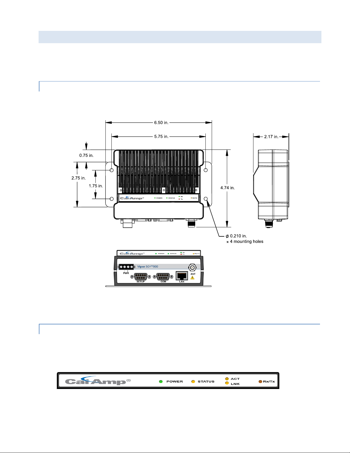
1.3.1. CHASSIS DIMENSIONS
The following figure shows the dimensions of the Viper chassis and attached mounting plate.
Figure 1 – Viper SC+ Chassis and Mounting Plate O verall Dimensions and Mounting Hole Locations
The equipment is intended for installation only in a RESTRICTED ACCESS LOCATION per EN60950-1:2006.
1.3.2. LED PANEL
There are five (5) Tri-Color LEDs in the LED panel of the Viper as shown in the following figure. Their functionality is
described in the following table.
Figure 2 – Viper LED panel
Viper SC+™ IP Router for Licensed Spectrum PN 001-5008-000 Rev. C | Page 2
Page 13
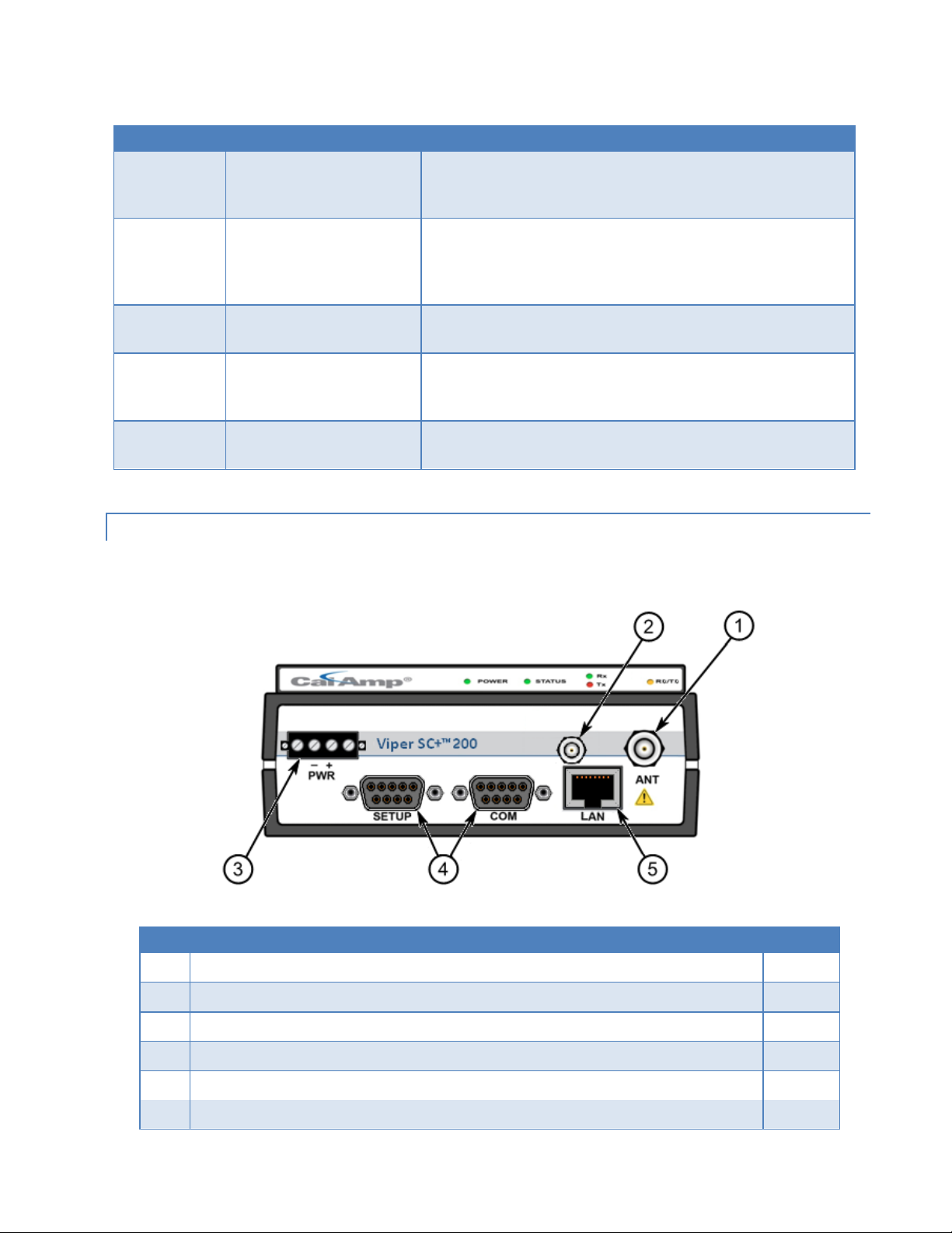
Table 1 – LED Functionality
LED
Color
Definition
POWER
Green (Solid)
Green (Blinking)
Red
Viper SC+ ready, normal operations
Upgrade in progress
Viper SC+ hardware fault
STATUS
Green
Blinking Green
Red
Amber (Solid or Blinking)
Viper SC+ no faults, normal operations
Viper SC+ scanning for neighbors
Viper SC+ has a fault condition; check unit status
Viper SC+ detects high background noise
ACT
Blinking Green
Off
Ethernet activity detected on PHY link (RJ45 / LAN)
No Ethernet activity on PHY link (RJ45 / LAN)
LNK
Amber
Green
Off
Ethernet connection Established, 100 Mbps (RJ45 / LAN)
Ethernet connection Established, 10 Mbps (RJ45 / LAN)
No Ethernet connection (RJ45 / LAN)
Rx/Tx
Green
Red
Receiving data
Transmitting data
Item
Description
Quantity
1
50 Ohm TNC Female Antenna connector
1
2
50 Ohm SMA Female Receive Antenna connector — Dual-Port models only.
1
3
Right-angle Power Connector (10-30 V DC)
1
4
DE-9F RS-232 ports: one (1) labeled Setup; one (1) labeled COM
2
5
10 Base T Auto-MDIX RJ-45 Ethernet LAN connection — VHF/UHF models, or
1
10/100 Base T/Tx Auto-MDIX RJ-45 Ethernet LAN connection — 220/900 MHz models.
1
1.3.3. FRONT PANEL
The front panel, shown in the following figure, has connections described in the following table.
Figure 3 – Front Panel (Dual Port Viper SC+ 200 Shown)
Table 2 – Front Panel Connections
Viper SC+™ IP Router for Licensed Spectrum PN 001-5008-000 Rev. C | Page 3
Page 14
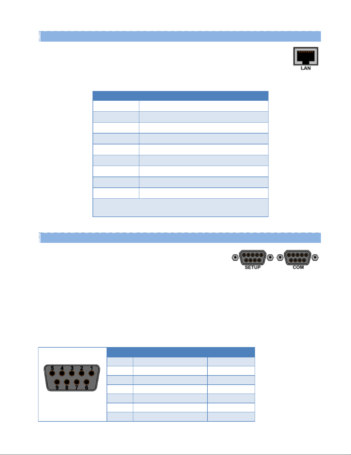
1.3.3.1. Ethernet LAN Port
The Ethernet LAN port is an RJ-45 receptacle with a 10 Base T (or 100 Base T/Tx for 220 MHz and 290
MHz models) Ethernet connection and Auto-MDIX. Refer to the following table for pin-out descriptions
and Section 4.4.6 to configure the LAN settings for this port.
Contact
10BaseT Signal
1
TXP
(1)
2
TXN
(1)
3
RXP
(1)
4
SPARE
5
SPARE
6
RXN
(1)
7
SPARE
8
SPARE
SHELL
Shield
(1)
The name shows the default function. Given the Auto-MDIX capability
of the Ethernet transceiver, Tx and Rx functions could be swapped.
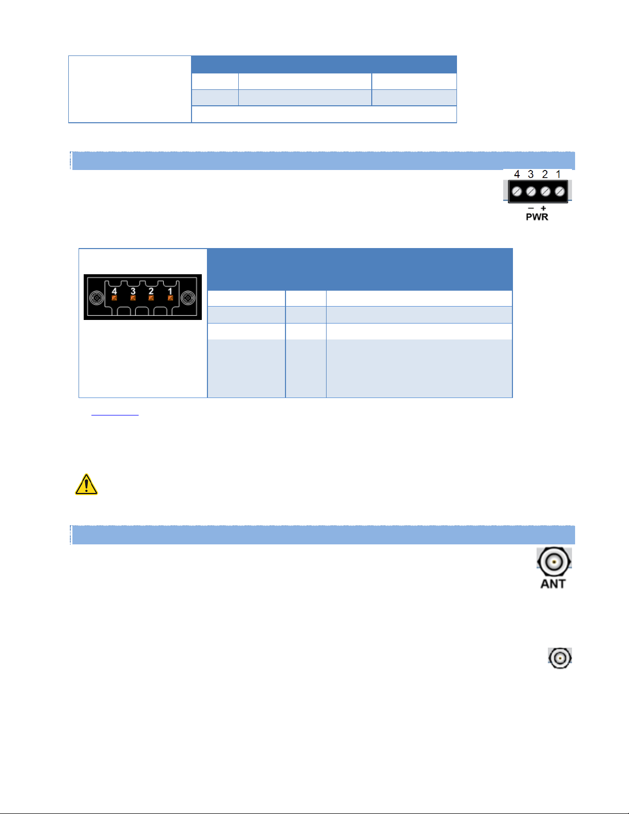
The SETUP and COM serial connections are DE-9F RS-232 ports. Refer to the
following table for pin-out descriptions and Section 4.3.4 for control line
configurations of DCD, DTR, RTS, and CTS control lines.
SETUP / COM port
Pin-Out
Contact Numbering
Contact
Signal Name
Signal Direction
1
Data Carrier Detect (DCD)
(1)
DTE ← DCE
2
Receive Data (RxD)
DTE ← DCE
3
Transmit Data (TxD)
DTE → DCE
4
Data Terminal Ready (DTR)
DTE → DCE
5
Signal Ground (GND)
DTE ― DCE
6
Data Set Ready (DSR)
(2)
DTE ← DCE
7
Ready To Send (RTS)
(1)
DTE → DCE
Table 3 – Pin-out for IEEE-802.3 RJ-45 Receptacle Contacts
1.3.3.2. SETUP and COM Port s
Serial port considerations:
Viper SETUP and COM ports are Data Communication Equipment (DCE) devices.
In general, equipment connected to the Viper serial ports is Data Terminal Equipment (DTE) and a straight-through
Note: If a DCE device is connected to the Viper serial ports, a null-modem cable or adapter is required.
Table 4 – Pin-Out for DCE SETUP and COM Port, 9 Contact DE -9 Connector
cable is recommended.
Viper SC+™ IP Router for Licensed Spectrum PN 001-5008-000 Rev. C | Page 4
Page 15
SETUP / COM port
Contact
Signal Name
Signal Direction
8
Clear To Send (CTS)
(1)
DTE ← DCE
9
Ring Indicator (RI)
(3)
DTE ― DCE
(1)
Programmable
(2)
Always asserted
(3)
Future use
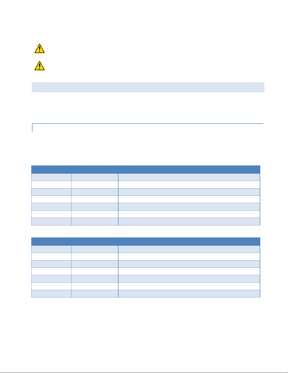
Viper is supplied with a right-angle power connector (10-30 V DC). The following table shows the
pin-out of the power connector.
Power Connector
Pin-Out
Contact
number
(Left to Right)
Color
Description
4
Fan Power Output (5V)
3
Black
Ground
2
Red
Positive (10-30) VDC
1
White
Enable to Power Management — See
Note
Power – Viper is awake.
No Power – Viper is asleep.
WARNING – EXPLOSION HAZARD - Do not disconnect unless power has been removed or the area is
known to be non-hazardous.
Standard Viper SC+ models have a 50 ohm TNC female antenna connector. This connection functions for
both transmit and receive.
Dual port models feature a 50 ohm TNC female antenna connector functioning for transmit (only) and a 50
ohm SMA female antenna connector functioning for receive (only). The separate receive antenna connector is
ideal for applications that require additional receive filtering, external PA(s) and other options.
1.3.3.3. Power Connector
Table 5 – Pin-Out of the Power Connector
See Appendix B for detailed voltage and current requirements.
Note: The white Enable line must be tied to the red positive lead of the connector for the Viper to power up and
function.
1.3.3.4. Antenna Connector
Warning: See Selecting Antenna and Lightning Arrestor combinations for information about types of lightning
arrestors to not use and good design practices to use when selecting a lightning arrestor for use with an antenna.
Warning: The transmit antenna port must not be connected directly to the receive antenna port of the Dual Port
Viper SC+. Excessive power into the receive antenna port will damage the radio. Input power to the receiver should
not exceed 17 dBm (50 mW).
Viper SC+™ IP Router for Licensed Spectrum PN 001-5008-000 Rev. C | Page 5
Page 16
To reduce potential interference, the antenna type and its gain should be chosen to ensure the effective isotropic
WARNING – EXPLOSION HAZARD - Do not disconnect unless power has been removed or the area is
known to be non-hazardous.
WARNING – EXPLOSION HAZARD – Substitution of components may impair suitability for Class I,
Division 2. The unit must be powered with a Listed Class 2 or LPS power supply or equivalent.
Model Number
Frequency Range
Description
140-5018-502
136 - 174 MHz
Viper SC+ 136-174 MHz 6.25-50 kHz BW
140-5018-503
136 - 174 MHz
Viper SC+ 136-174 MHz 6.25-50 kHz BW 2RFP
140-5118-502
136 - 174 MHz
Viper SC+ Std. BS 136-174 MHz 6.25-50 kHz BW
140-5318-502
136 - 174 MHz
Viper SC+ Rdnt. BS 136-174 MHz 6.25-50 kHz BW
140-5318-503
136 - 174 MHz
Viper SC+ Rdnt. BS 136-174 MHz 6.25-50 kHz BW 2RFP
250-5018-500
136 - 174 MHz
Viper SC+ 136-174 MHz Developer’s Kit (2 Vipers)
250-5018-510
136 - 174 MHz
Viper SC+ 136-174 MHz Developer’s Kit (3 Vipers)
Model Number
Frequency Range
Description
140-5028-504
215 - 240 MHz
Viper SC+ 215-240 MHz 6.25-100 kHz BW
140-5028-505
215 - 240 MHz
Viper SC+ 215-240 MHz 6.25-100 kHz BW 2RFP
140-5128-504
215 - 240 MHz
Viper SC+ Std. BS 215-240 MHz 6.25-100 kHz BW
140-5328-504
215 - 240 MHz
Viper SC+ Rdnt. BS 215-240 MHz 6.25-100 kHz BW
140-5328-505
215 - 240 MHz
Viper SC+ Rdnt. BS 215-240 MHz 6.25-100 kHz BW 2RFP
250-5028-502
215 - 240 MHz
Viper SC+ 215-240 MHz Developer’s Kit (2 Vipers)
250-5028-512
215 - 240 MHz
Viper SC+ 215-240 MHz Developer’s Kit (3 Vipers)
radiated power (EIRP) is not more than required for successful communication.
1.4. PART NUM BERS AND AVA ILABILITY
Viper SC+™ is available in various models. Each is available with a range of features, kits, and accessories. Refer to the
following table for product availability and part numbers for ordering. Refer to tables that follow for Viper SC+
accessories and for antenna options and kits.
1.4.1. VIPER SC+ RADIO
The following tables list Viper SC+ radios and kit part numbers.
Table 6 – Viper SC+ Radio and Kit Part Numbers
Viper SC+ 100 Series, 136 - 174 MHz
Viper SC+ 200 Series, 215 - 240 MHz
Key to abbreviations: BW = bandwidth, BS = Base Station, Std. = standard, Rdnt. = redundant, 2RFP = Dual RF Port.
Viper SC+™ IP Router for Licensed Spectrum PN 001-5008-000 Rev. C | Page 6
Page 17
Viper SC+ 400 Series, Range 3
Model Number
Frequency Range
Description
140-5048-302
406.1 - 470 MHz
Viper SC+ 406.1-470 MHz 6.25-50 kHz BW
140-5048-303
406.1 - 470 MHz
Viper SC+ 406.1-470 MHz 6.25-50 kHz BW 2RFP
140-5148-302
406.1 - 470 MHz
Viper SC+ Std. BS 406.1-470 MHz 6.25-50 kHz BW
140-5348-302
406.1 - 470 MHz
Viper SC+ Rdnt. BS 406.1-470 MHz 6.25-50 kHz BW
140-5348-303
406.1 - 470 MHz
Viper SC+ Rdnt. BS 406.1-470 MHz 6.25-50 kHz BW 2RFP
250-5048-300
406.1 - 470 MHz
Viper SC+ 406.1-470 MHz Developer’s Kit (2 Vipers)
250-5048-310
406.1 - 470 MHz
Viper SC+ 406.1-470 MHz Developer’s Kit (3 Vipers)
Model Number
Frequency Range
Description
140-5048-502
450 - 512 MHz
Viper SC+ 450-512 MHz 6.25-50 kHz BW
140-5048-503
450 - 512 MHz
Viper SC+ 450-512 MHz 6.25-50 kHz BW 2RFP
140-5148-502
450 - 512 MHz
Viper SC+ Std. BS 450-512 MHz 6.25-50 kHz BW
140-5348-502
450 - 512 MHz
Viper SC+ Rdnt. BS 450-512 MHz 6.25-50 kHz BW
140-5348-505
450 - 512 MHz
Viper SC+ Rdnt. BS 450-512 MHz 6.25-50 kHz BW 2RFP
250-5048-500
450 - 512 MHz
Viper SC+ 450-512 MHz Developer’s Kit (2 Vipers)
250-5048-510
450 - 512 MHz
Viper SC+ 450-512 MHz Developer’s Kit (3 Vipers)
Model Number
Frequency Range
Description
140-5098-304
880 - 902 MHz
Viper SC+ 880-902 MHz 6.25-100 kHz BW
140-5098-305
880 - 902 MHz
Viper SC+ 880-902 MHz 6.25-100 kHz BW 2RFP
140-5198-304
880 - 902 MHz
Viper SC+ Std. BS 880-902 MHz 6.25-100 kHz BW
140-5398-304
880 - 902 MHz
Viper SC+ Rdnt. BS 880-902 MHz 6.25-5100 kHz BW
140-5398-305
880 - 902 MHz
Viper SC+ Rdnt. BS 880-902 MHz 6.25-100 kHz BW 2RFP
250-5098-300
880 - 902 MHz
Viper SC+ 880-902 MHz Developer’s Kit (2 Vipers)
250-5098-310
880 - 902 MHz
Viper SC+ 880-902 MHz Developer’s Kit (3 Vipers)
Model Number
Frequency Range
Description
140-5098-504
928 - 960 MHz
Viper SC+ 928-960 MHz 6.25-100 kHz BW
140-5098-505
928 - 960 MHz
Viper SC+ 928-960 MHz 6.25-100 kHz BW 2RFP
140-5198-504
928 - 960 MHz
Viper SC+ Std. BS 928-960 MHz 6.25-100 kHz BW
140-5398-504
928 - 960 MHz
Viper SC+ Rdnt. BS 928-960 MHz 6.25-100 kHz BW
140-5398-505
928 - 960 MHz
Viper SC+ Rdnt. BS 928-960 MHz 6.25-100 kHz BW 2RFP
250-5098-500
928 - 960 MHz
Viper SC+ 928-960 MHz Developer’s Kit (2 Vipers)
250-5098-510
928 - 960 MHz
Viper SC+ 928-960 MHz Developer’s Kit (3 Vipers)
Viper SC+ 400 Series, Range 5
Viper SC+ 900 Series, Range 3
Viper SC+ 900 Series, Range 5
Key to abbreviations: BW = bandwidth, BS = Base Station, Std. = standard, Rdnt. = redundant, 2RFP = Dual RF Port.
Viper SC+™ IP Router for Licensed Spectrum PN 001-5008-000 Rev. C | Page 7
Page 18
EN 300 113 ETSI Compliant and AS/NZ Compliant Models
Model Number
Frequency Range
Description
140-5018-600
142 - 174 MHz
Viper SC+ 142-174 MHz 12.5-25 kHz BW ETSI AS/NZ
140-5018-601
142 - 174 MHz
Viper SC+ 142-174 MHz 12.5-25 kHz BW ETSI AS/NZ 2RFP
140-5118-600
142 - 174 MHz
Viper SC+ Std. BS 136-174 MHz 12.5-25 kHz BW ETSI AS/NZ
140-5118-601
142 - 174 MHz
Viper SC+ Std. BS 136-174 MHz 12.5-25 kHz BW ETSI AS/NZ 2RFP
140-5318-600
142 - 174 MHz
Viper SC+ Rdnt. BS 142-174 MHz 12.5-25 kHz BW ETSI AS/NZ
140-5318-601
142 - 174 MHz
Viper SC+ Rdnt. BS 142-174 MHz 12.5-25 kHz BW ETSI AS/NZ 2RFP
Model Number
Frequency Range
Description
140-5048-400
406.1 - 470 MHz
Viper SC+ 406.1-470 MHz 12.5-25 kHz BW ETSI AS/NZ
140-5048-401
406.1 - 470 MHz
Viper SC+ 406.1-470 MHz 12.5-25 kHz BW ETSI AS/NZ 2RFP
140-5148-400
406.1 - 470 MHz
Viper SC+ Std. BS 406.1-470 MHz 12.5-25 kHz BW ETSI AS/NZ
140-5148-401
406.1 - 470 MHz
Viper SC+ Std. BS 406.1-470 MHz 12.5-25 kHz BW ETSI AS/NZ 2RFP
140-5348-400
406.1 - 470 MHz
Viper SC+ Rdnt. BS 406.1-470 MHz 12.5-25 kHz BW ETSI AS/NZ
140-5348-401
406.1 - 470 MHz
Viper SC+ Rdnt. BS 406.1-470 MHz 12.5-25 kHz BW ETSI AS/NZ 2RFP
Model Number
Frequency Range
Description
140-5048-600
450 - 512 MHz
Viper SC+ 450-512 MHz 12.5-25 kHz BW ETSI AS/NZ
140-5048-601
450 - 512 MHz
Viper SC+ 450-512 MHz 12.5-25 kHz BW ETSI AS/NZ 2RFP
140-5148-600
450 - 512 MHz
Viper SC+ Std. BS 450-512 MHz 12.5-25 kHz BW ETSI AS/NZ
140-5148-601
450 - 512 MHz
Viper SC+ Std. BS 450-512 MHz 12.5-25 kHz BW ETSI AS/NZ 2RFP
140-5348-600
450 - 512 MHz
Viper SC+ Rdnt. BS 450-512 MHz 12.5-25 kHz BW ETSI AS/NZ
140-5348-601
450 - 512 MHz
Viper SC+ Rdnt. BS 450-512 MHz 12.5-25 kHz BW ETSI AS/NZ 2RFP
Description
Part Number
Fan Kit, Viper SC+, Factory Installed
150-5008-001
Fan Kit, Viper SC+, Field Installed
150-5008-002
Table 7 – Viper SC+ EN 300 113 ETSI Compliant and AS/NZ Compliant Radio and Kit Part Numbers
Viper SC+ 100 Series, 142 – 174 MHz
Viper SC+ 400 Series, Range 3
Viper SC+ 400 Series, Range 5
Key to abbreviations: BW = bandwidth, BS = Base Station, Std. = Standard, Rdnt. = Redundant, 2RFP = Dual RF Port.
1.4.2. FAN KITS AND CABLES
The following tables list standard fan kits and cables available for use with the Viper SC+™.
Table 8 – Viper SC+ Fan Kits
Viper SC+™ IP Router for Licensed Spectrum PN 001-5008-000 Rev. C | Page 8
Page 19
Table 9 – Viper SC+™ Power Cable
Description
Part Number
Power Cable, Viper SC+
897-5008-010
Length
Connectors
Type
Part Number
18 inches
TNC-Male to N-Male
RG-400
140-5018-502
48 inches
TNC-Male to N-Male
RG-400
140-5018-503
72 inches
TNC-Male to N-Male
RG-400
250-5018-502
18 inches
TNC-Male to N-Female
RG-400
140-5118-502
Description
Item
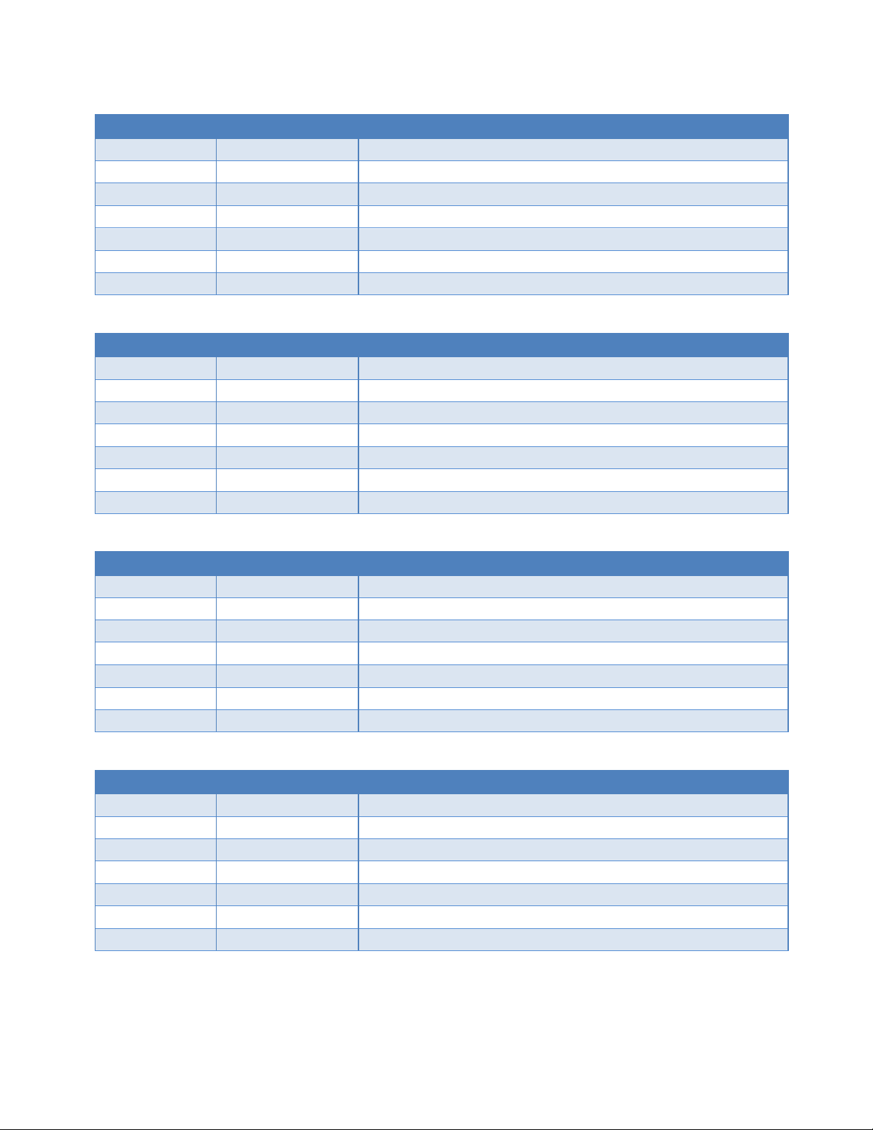
Viper SC+ IP Router
60 in. Cat 5 Ethernet Cable
Power Cable
Table 10 – Coaxial Adapter Cables
1.5. COMPO NENTS
1.5.1. BASIC UNIT
The following items are included with the Viper SC+ basic unit.
Viper SC+™ IP Router for Licensed Spectrum PN 001-5008-000 Rev. C | Page 9
Page 20
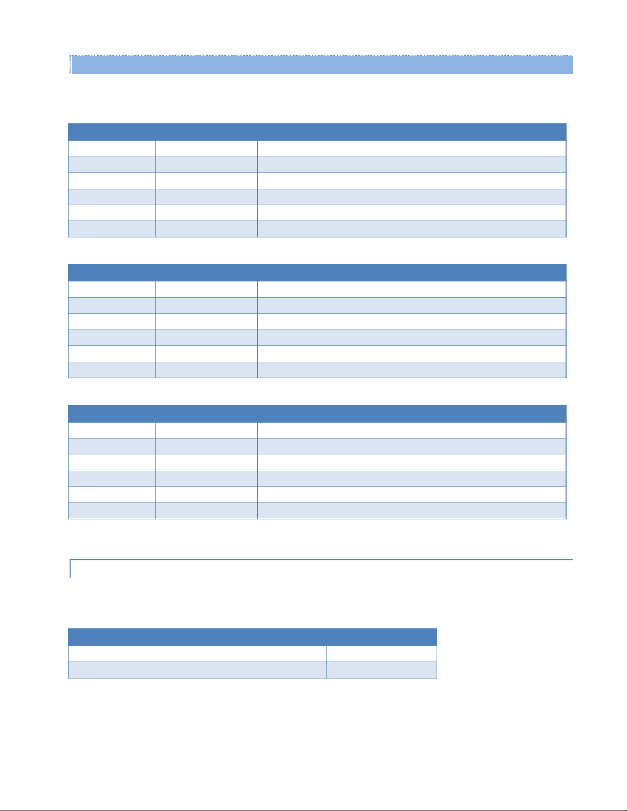
1.5.2. TWO- AND THREE-PIEC E KIT ADDITIONAL ITEMS
Description
Item
SMA Male to BNC Female
Connector
SMA Female to BNC Male
Connector
TNC Male to BNC Female
Connector
Mini Circuits 5 W 20 dB
Attenuator
Flex Rubber Duck Antenna
(VHF, UHF, or 900 MHz)
120 VAC to 13.8 VDC
4 A Power Supply
The following items are included with two- and three-piece Viper SC+™ Developer Kits.
Viper SC+™ IP Router for Licensed Spectrum PN 001-5008-000 Rev. C | Page 10
Page 21

2. NETWORK ARCHITECTURE AND SYS TE M PLA NNING
This section discusses network architecture, basic network types, interfacing modems and DTE, data protocols for
efficient channel operation, as well as providing tips for selecting an appropriate site, antenna selection, and reducing
the chance of harmful interference.
2.1. NETWORK ARCHITECTURE
In a radio system, only one radio should transmit at a time. If two radios transmit at the same time to another radio, RF
collisions occur. Collisions will slow data traffic and may corrupt data. Most SCADA networks have a device that is
configured to be the ‘polling master’. It is the responsibility of this polling master to control RF traffic so RF collisions do
not occur.
Viper has RF collision avoidance technology (checks the air wave for a carrier before transmitting) and Ethernet CSMA
(Carrier Sense Multiple Access). CSMA is an Ethernet collision avoidance mechanism technology built into to all
Ethernet connections. However, these technologies must still be supplemented by the HMI/PLC polling master to
optimize RF data traffic.
Some HMI/PLC Ethernet applications may depend solely on Ethernet CSMA to control the flow of messages to avoid RF
collisions in a Viper data network. This may flood the network with multiple polling messages, making it difficult for the
RTUs to acquire the airwave to transmit their reply messages. This will cause the RTUs to compete for airtime and a
dominant RTU may be created.
While the dominant RTU/radio is transmitting, the other RTUs will send their reply messages to their connected Viper
SC. Viper SCs will buffer reply messages because the dominant RTU/radio is transmitting (carrier is present). A Viper SC
will buffer (while a carrier is present) a reply message until it can capture the airwave (carrier absent) to transmit.
There could be five or six RTU/radios in a small system (or 10 or 20 in a large system), which could be trying to capture
the airwaves to transmit. The RTUs will not respond in the order they were polled but will respond when they are ready
and have captured the airwaves. The dominant RTU is created because it happens to reply at just the right time and be
in the right order in the polling sequence.
A common method for a polling master to manage RF traffic is for the HMI/PLC polling master to poll one remote at a
time. The next polling message is not sent until the current message has been completed (“Done”) or has timed out.
This prevents more than one outstanding polling message. Ladder logic programs typically refer to these parameters as
the message “Done” and “Error” bits. The “Done” and “Error” bits parameter values can be adjusted for longer timeout
values, if required.
Because the Viper SC has the ability to use two completely different and separate SCADA polling protocols, it is
important to have interaction between the two protocols. The Viper SC can send out an Ethernet TCP/IP polling
message and also an RS232 polling message, which may or may not be generated by the same HMI/PLC. CalAmp
recommends the user program the polling sequence in each protocol with logic that interacts with the other’s protocol
“Done” and “Error” bits. The Ethernet polling protocol would not be allowed to send a message until the current
Ethernet message is either “Done” or “Error” and the previous RS232 message are either “Done” or “Error” bits are set.
The RS232 polling protocol would also have a similar logic.
Viper SC+™ IP Router for Licensed Spectrum PN 001-5008-000 Rev. C | Page 11
Page 22
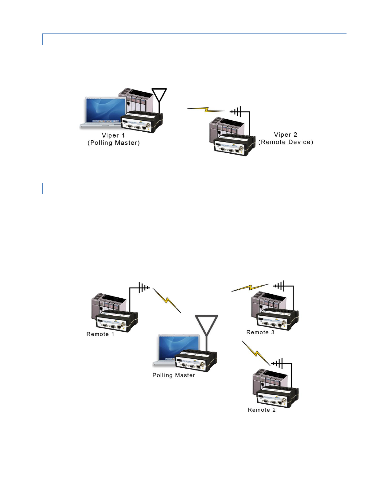
2.1.1. POINT-TO-POINT NETWORK
A point-to-point network is the simplest type of network, and may be used for connecting a pair of PCs, a host
computer and a terminal, a SCADA polling master and one remote, or a wide variety of other networking applications.
Figure 4 – Point-to-Point Network
2.1.2. POINT-TO-MULTIPOINT NETWORK
A Point-to-Multipoint network is a common network type used in SCADA and other polling systems. The Master Polling
station communicates with any number of remotes and controls the network by issuing polls and waiting for remote
responses. Individual PLC/RTU remotes manage addressing and respond when their individual addresses are queried.
PLC/RTU unit addresses are maintained in a scanning list stored in the host program or master terminal device at the
SCADA host site. Communications equipment is transparent and does not interact with specific remotes; all data is
coupled to the host on a single data line (such a network is commonly used with synchronous radio modems and
asynchronous radio modems).
Figure 5 – Point-to-Multipoint Network
Viper SC+™ IP Router for Licensed Spectrum PN 001-5008-000 Rev. C | Page 12
Page 23
2.1.3. REPORT BY EXCEPTION CO NFIGURATION
In a true Report by Exception configuration, the remotes send data to the master only when an event or exception has
occurred in the remote. However, most Report by Exception systems have a master/remote polling component. The
master polls the remotes once every hour or half-hour to ensure there is still a valid communication path. In a Report
by Exception configuration, there will not be a master controlling RF traffic and RF collisions will often occur.
Viper has several collision avoidance features to help minimize collisions. Viper is a “polite radio”. This means Viper will
check the RF traffic on the receive channel before transmitting. If there is no RF traffic present (no carrier present) it
will transmit. If there is RF traffic (carrier present) the Viper SC will buffer the data. Viper will transmit the buffered
data when there is no RF traffic present.
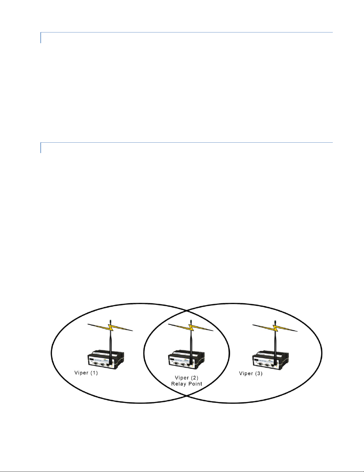
2.1.4. EXTENDING THE COVERAGE AREA WITH A RELAY POINT
A Viper can be configured as a Relay Point (see the following figure). Relay Points provide store and forward repeating
of necessary information from one coverage area to the next. In Bridge mode all traffic is forwarded. In Router mode,
only Broadcast Packets and address specific packets are forwarded. There may be multiple Relay Points to extend
coverage over several hops.
Note: Multiple relay points in a single network may slow the flow of data traffic.
Serial data is always sent out as a broadcast message. A broadcast message cannot take advantage of IP routing mode
so it must use relay points to move from one RF coverage area to another. However, it may be possible to configure
the Viper SC+ so that it may be able to take advantage of the router mode feature and collision avoidance features of
the router mode.
An option to configure the Viper SC+ as a relay point is in the first step of the Viper Setup Wizard or later in the RF
Network tab of the RF Network Settings page. Instructions for completing the Viper Setup Wizard and for configuration
options in the Viper Web Interface tabbed pages are provided later in this User Manual.
Figure 6 – Extending coverage areas by configuring the Viper SC+ as a relay point
Viper SC+™ IP Router for Licensed Spectrum PN 001-5008-000 Rev. C | Page 13
Page 24

2.2. IP FORWARDING MO DES
Ethernet Subnet Mask 255.255.255.0
Network ID 192.168.205.0
Broadcast Address 192.168.205.255
Viper #1 192.168.205.1/24
PLC/RTU #1 192.168.205.10/24
Computer #1 192.168.205.100/24
Viper #2 192.168.205.2/24
PLC/RTU #2 192.168.205.20/24
Viper #3 192.168.205.3/24
PLC/RTU #3 192.168.205.30/24
Viper #4 192.168.205.4/24
PLC/RTU #4 192.168.205.40/24
…
Viper #100: 192.168.205.253/24
PLC/RTU #100: 192.168.205.254/24
All Ethernet capable devices, or hosts, have at least one IP address and a subnet mask assigned to it. The IP address
identifies a specific device and the subnet mask tells the device which other IP addresses it can directly communicate
with. When any host needs to communicate with another device that is not within the same local area network it will
first send the data packet to the gateway or router. The gateway or router will forward the packet to the desired
location. Often times a packet will pass through several gateways or routers to get to its final destination.
The Viper SC+ has two different modes of operation:
Bridge Mode – Bridge mode is for quick setup of units all on the same network.
Router Mode — Router mode is for advanced networks.
Both of these modes are explained in the sections that follow.
2.2.1. BRIDGE MODE
Bridge mode is the simplest configuration for all Viper networks. Viper may be configured for bridge mode only when
all devices are located on the same Local Area Network (LAN). Thus, all units in the network can communicate directly
with all other units in the network.
Each Viper has only one IP address assigned to it and the subnet mask is the same for every Viper in the network.
Bridge communications does not require each Viper to have a unique IP address, but it is highly recommended and
necessary for remote programming of the radio.
Every Viper ships from the factory with the default Ethernet IP address of 192.168.205.1 and a subnet mask of
255.255.255.0. The default subnet of the Viper consists of addresses from 192.168.205.0 to 192.168.205.255. The first
and last IP address of each subnet is reserved, no matter what the subnet size is. The first IP address in the subnet is
the Network ID. The last IP address in the subnet is the Broadcast Address.
Bridge Mode Example 1
This example illustrates a sample Viper network. The subnet consists of IP addresses ranging from 192.168.205.0 to
192.168.205.255. The subnet mask is 255.255.255.0. This subnet is sometimes indicated as 192.168.205.1/24 since the
subnet mask 255.255.255.0 contains 24 ones (followed by 8 zeros) when converted to binary.
The first address 192.168.205.0 is reserved for the Network ID.
The last address 192.168.205.255 is reserved for the broadcast address.
There are 254 valid IP addresses that may be assigned to hosts on the network.
Viper SC+™ IP Router for Licensed Spectrum PN 001-5008-000 Rev. C | Page 14
Page 25
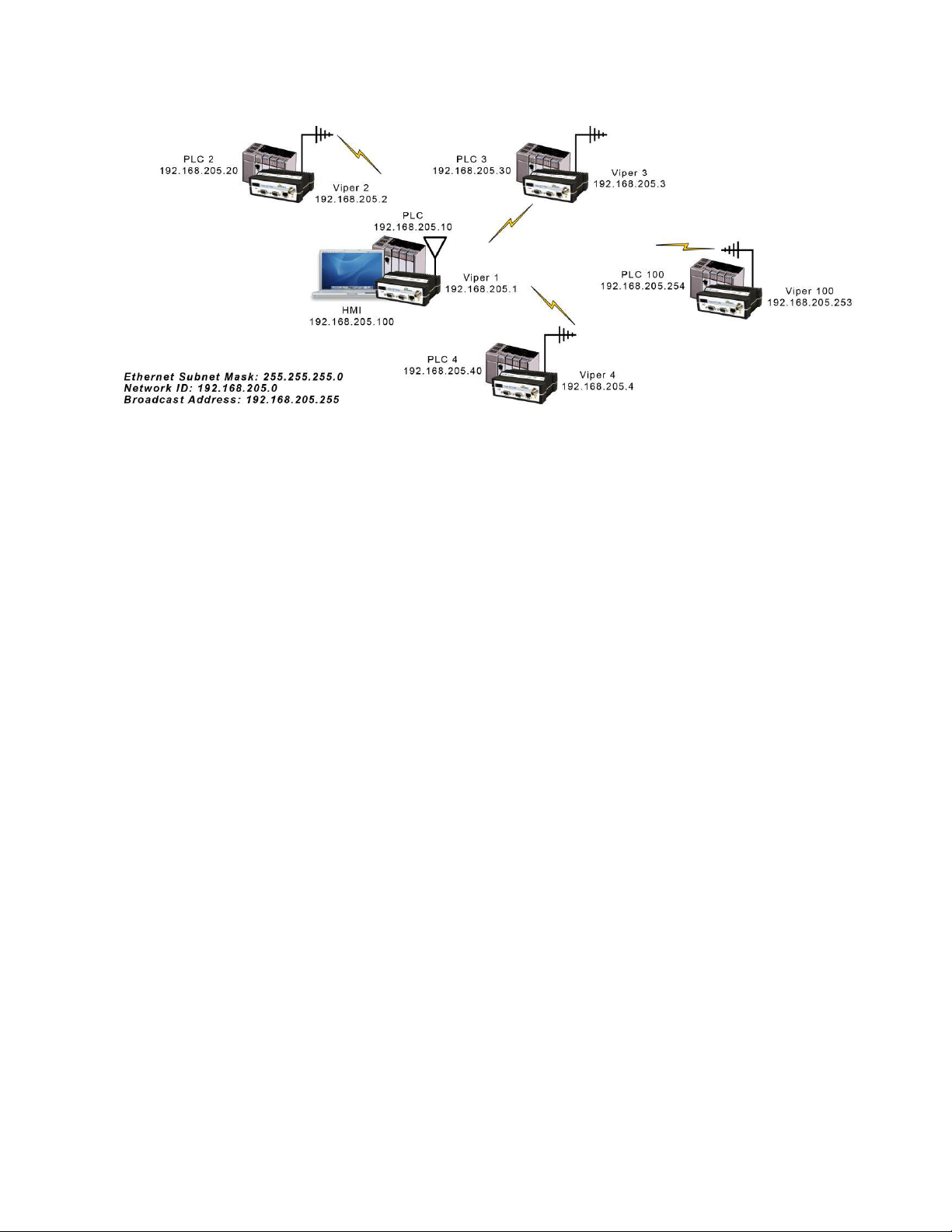
Figure 7 – Bridge Mode Example 1
Ethernet Subnet Mask 255.255.255.0
Network ID 172.20.0.0
Broadcast Address 172.20.255.255
Viper #1 172.20.0.1/16
Viper #2 172.20.0.2/16
Viper #3 172.20.0.3/16
…
Viper #105 172.20.0.015/16
PLC/RTU #1 172.20.255.1/16
PLC/RTU #2 172.20.255.2/16
PLC/RTU #3 172.20.255.3/16
…
PLC/RTU #250 172.20.255.250/16
Computer #1 172.20.138.1/16
…
Computer #500 172.20.255.254/ 16
Bridge Mode Example 2
The subnet for this Viper network is comprised of devices with IP addresses ranging from 172.20.0.0 to 172.20.255.255.
The subnet mask is 255.255.0.0. The shorthand notation is: 172.20.0.1/16 since the subnet mask 255.255.0.0 contains
16 ones (followed by 16 zeros) when converted to binary.
The first address 172.20.0.0 is reserved for the Network ID.
The last address 172.20.255.255 is reserved for the broadcast address.
There are 65534 valid IP addresses available to be assigned to hosts on the network.
Viper SC+™ IP Router for Licensed Spectrum PN 001-5008-000 Rev. C | Page 15
Page 26
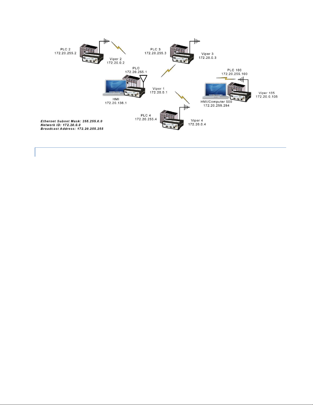
Figure 8 – Bridge Mode Example 2
2.2.2. ROUTER MODE
Router mode allows greater network configuration flexibility, allows the use of a variety of protocols, and also adds RF
diagnostics capability to Viper networks. Diagnostics can be retrieved through the Ethernet port of the Viper. More
information about Viper RF diagnostics is provided in section 4.8 Diagnostics.
Router mode requires the setup of Ethernet IP and Serial IP addresses and is recommended only for users who have
IT/Network support readily available to them and/or the authorization required to make changes in to the network.
In Router mode, each Viper uses two IP addresses:
An Ethernet IP Address
An RF IP Address
Every Viper is factory configured with a default Ethernet IP Address 192.168.205.1 and a unique RF IP address. This RF
IP address will have the form 10.x.y.z where x, y, and z is based on the last 6 digits of the unit’s Ethernet MAC address.
The default network is 10.0.0.0/8.
In Router mode, each Viper must have its Ethernet IP Address on a unique network and all Vipers must have their RF IP
addresses on the same network. For consistent and reliable communication, the RF network addresses should not
overlap or contain any of the IP Addresses in the Ethernet network.
Router Mode Example 1
In this example, each Viper has an Ethernet IP address on a unique network. For Vipers #1, #2, and #3, each network
connected to their local Ethernet ports has 254 valid IP addresses that may be assigned to other hosts. The network
connected to Viper #4’s local Ethernet port has 65534 valid IP addresses.
Note 1 All Vipers’ RF IP addresses are on the same network. Because they are using the 10.0.0.0/8 network, all Vipers
may use the default RF IP address programmed by the factory.
Note 2 All the Viper Ethernet IP addresses are on different networks.
Note 3 Computers, PLCs, RTUs, or other Ethernet capable devices can be connected up to each Viper’s local Ethernet
interface. That device must be set with an IP address on the same network as the Ethernet interface of the
Viper it is connected with.
Viper SC+™ IP Router for Licensed Spectrum PN 001-5008-000 Rev. C | Page 16
Page 27
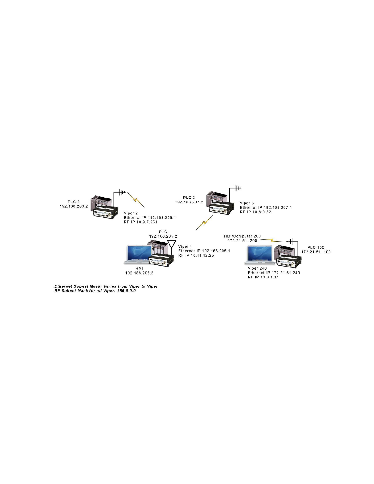
Ethernet Subnet Mask Varies from Viper to Viper.
RF Subnet Mask is the same for all units: 255.0.0.0 (hence /8 shown for all RF IP Addresses; 8 ones (24 zeros) binary.)
HMI/PLC/RTU Default Gateway points to the Viper that the HMI/PLC/RTU is connected to.
Viper #1: Ethernet IP Address: 192.168.205.1/24 RF IP Address: 10.11.12.25/8
PLC #1: 192.168.205.2/24 Default Gateway: 192.168.205.1
Computer/HMI #1: 192.168.205.3/24 Default Gateway: 192.168.205.1
Viper #2: Ethernet IP Address: 192.168.206.1/24 RF IP Address: 10.9.7.251/8
PLC #2: 192.168.206.2/24 Default Gateway 192.168.206.1
Viper #3: Ethernet IP Address: 192.168.207.1/24 RF IP Address: 10.8.0.52/8
PLC #3: 192.168.207.2/24 Default Gateway: 192.168.207.1
Computer #3: 192.168.207.3/24 Default Gateway: 192.168.207.1
Viper #4: Ethernet IP Address: 172.21.51.105/16 RF IP Address: 10.0.1. 11/8
PLC #4: 172.21.51.106/16 Default Gateway 172.21.51.106
Figure 9 – Router Mode Example 1
Router Mode Example 2
Each Viper has an Ethernet IP address on a unique network.
In this example, each network connected to the Viper’s local Ethernet port has 14 valid IP addresses that may be used
for the Viper, PLCs, RTUs, computers, or other Ethernet equipment that may be connected.
The subnet mask of the RF IP addresses has been changed to ensure that the RF IP network does not overlap any of the
Ethernet networks. In this scenario, the RF IP addresses must be manually programmed to ensure that every Viper has
an RF IP address in the network and that no RF IP address is used twice.
Viper SC+™ IP Router for Licensed Spectrum PN 001-5008-000 Rev. C | Page 17
Page 28
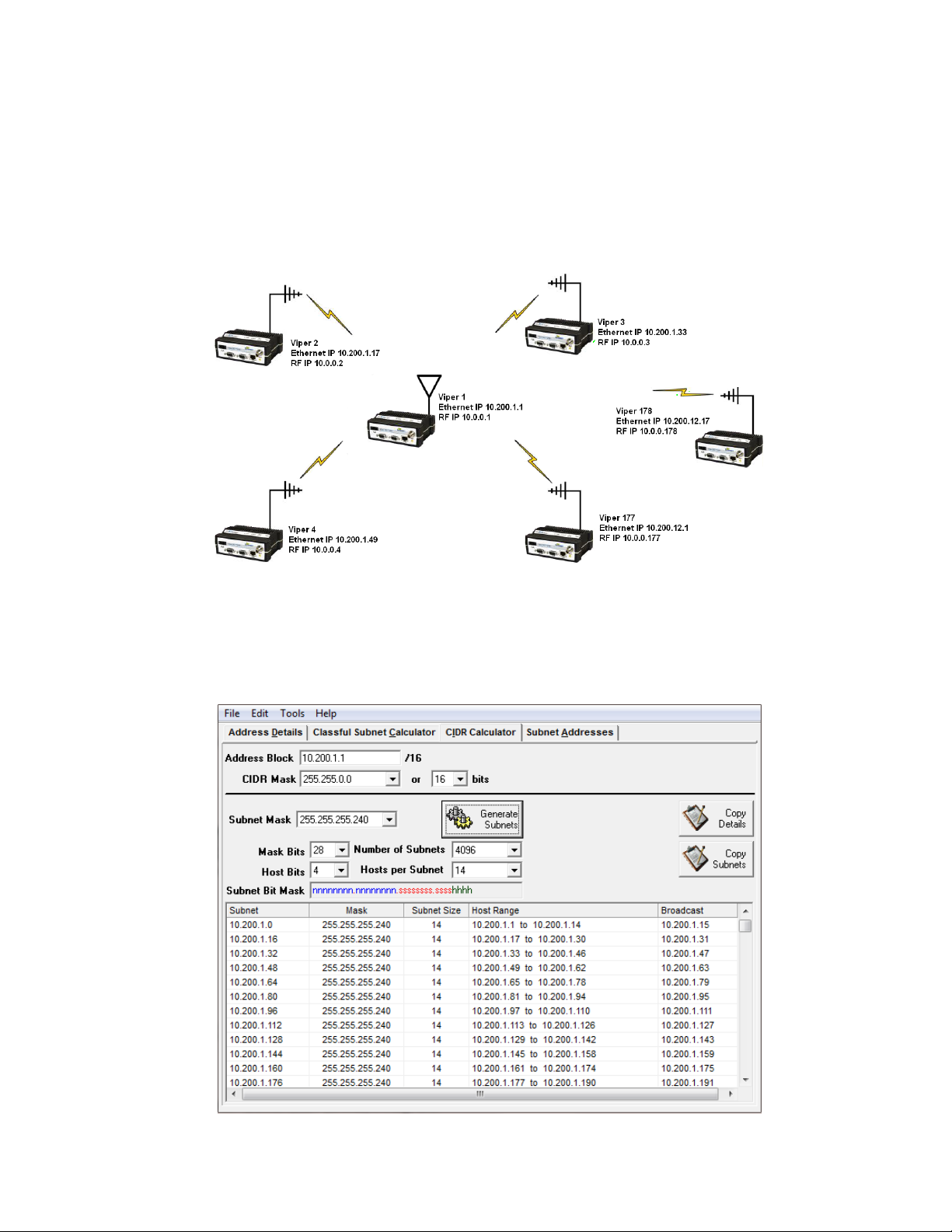
Viper #1: Ethernet IP Address: 10.200.1.1/28 RF IP Address: 10.0.0.1/16
Viper #2: Ethernet IP Address: 10.200.1.17/28 RF IP Address: 10.0.0.2/16
Viper #3: Ethernet IP Address: 10.200.1.33/28 RF IP Address: 10.0.0.3/16
Viper #4: Ethernet IP Address: 10.200.1.49/28 RF IP Address: 10.0.0. 4/16
…
Viper #177: Ethernet IP Address: 10.200.12.1/28 RF IP Address: 10.0.0.177/16
Viper #178: Ethernet IP Address: 10.200.12.17/28 RF IP Address: 10.0.0. 178/16
Figure 10 – Router Mode Example 2
Solarwinds™ Advanced Subnet Calculator (available as a free download from the Solarwinds website at
www.solarwinds.com) can be used to help calculate subnets as used in this example. The Advanced Subnet Calculator
will calculate and display the range of host IP addresses that can be used, as shown in the following figure.
Figure 11 – Router Mode Example 2 Subnet Calculations
Viper SC+™ IP Router for Licensed Spectrum PN 001-5008-000 Rev. C | Page 18
Page 29
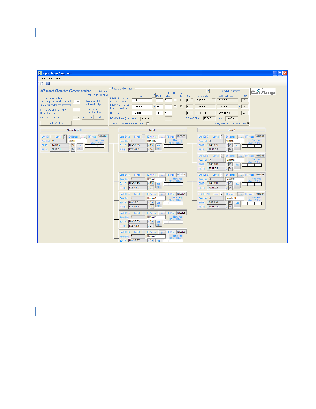
2.2.3. VIPER ROUTER GENERATOR (VRG) PROGRAM
CalAmp has developed a Viper Route Generator (VRG) application that assists in generating the Viper’s neighbor or
router tables and also generates the configuration files for all the radios in your project within minutes.
Figure 12 – Viper Route Generator tool
You should try to choose an IP addressing scheme so that the master Viper’s address is always first in a sequence and
then the remote IP addresses to follow in that sequence.
The VRG application can be downloaded from CalAmp. Contact CalAmp Technical Support to obtain the VRG
application and instructions for its use.
2.2.4. MULTISPEED NETWORKING
When using the Viper SC+ with a Viper SC+ multi-speed base station, it is possible to configure the network for
multispeed operation. With the base station enabled as the rate controller, the remote device becomes a rate follower.
The rate controller (base station) can be configured to talk at different over-the-air data rates for each remote Viper.
This allows the user to uniquely control the data rate for each RF link in the system using the Base Station configuration
interface web pages. The user can program RF links with strong signal strength to communicate at fast data rates and
RF links with low signal strength can be programmed to communicate at more-robust, slower data rates. Even if data
rates vary from Viper to Viper, every Viper in the network must be programmed for the same bandwidth.
Viper SC+™ IP Router for Licensed Spectrum PN 001-5008-000 Rev. C | Page 19
Page 30

An option to configure the Viper SC+ for multispeed networking is in the first step of the Viper Setup Wizard or later in
the RF Network tab of the RF Network Settings page. Instructions for completing the Viper Setup Wizard and for
configuration options in the Viper Web Interface tabbed pages are provided later in this User Manual.
Figure 13 – Viper SC+ Base Station with remote Vipers configured with different OTA data rates
2.3. UNDERSTANDING RF PATH REQUIREM ENTS
Radio waves are propagated when electrical energy produced by a radio transmitter is converted into magnetic energy
by an antenna. Magnetic waves travel through space. The receiving antenna intercepts a very small amount of this
magnetic energy and converts it back into electrical energy that is amplified by the radio receiver. The indicator of
strength of signal energy received by the receiver is called the Received Signal Strength Indication (RSSI) and is
expressed in dBm.
A radio modem requires minimum amount of received RF signal to operate reliably and provide adequate data
throughput. This is the radio receiver’s sensitivity. In most cases, spectrum regulators will define or limit the amount of
signal that can be transmitted and it will be noted in the FCC license. This is the effective isotropic radiated power
(EIRP). Transmitted power decays with distance and other factors as it moves away from the transmitting antenna.
Viper SC+™ IP Router for Licensed Spectrum PN 001-5008-000 Rev. C | Page 20
Page 31

2.4. SITE SELECTIO N AND SITE SURVEY
2.4.1. SITE SELECTION
For a successful installation, careful thought must be given to selecting the site for each radio. These requirements can
be quickly determined in most cases. Suitable sites should provide the following.
Protection from direct weather exposure.
A source of adequate and stable primary power.
Suitable entrances for antenna, interface, or other cabling.
Antenna location with an unobstructed transmission path to all remote radios in the system.
2.4.2. SITE SURVEY
A Site Survey is an RF propagation study of the RF path between two points or between one point and multiple points.
UHF radio signals travel primarily by line of sight and obstructions between the sending and receiving stations will
affect system performance. Signal propagation is also affected by attenuation from obstructions such as terrain,
foliage, or buildings in the transmission path. A Site Survey is recommended for most projects to determine the optimal
RF paths for each link. This is especially true when more than one RF coverage area is required. A Site Survey will
determine the best unit location for the Relay Points.
2.5. SELECTING ANTENNA AND LIGHTNING ARRESTOR COMBINATIONS
Very Important! Before you deploy your system you must read and understand this section.
RF engineers and installers have seen many types of radio installations over the years, and they know there are certain
details that must not be overlooked at any installation. Most radio installations contain some form of lightning
protection. However, the wrong combination of antenna and lightning arrestor can create high voltage transients on
the radio’s antenna port having devastating impacts on the life and reliability of modern day radio equipment.
2.5.1. LIGHTNING ARRESTOR OVERVIEW
Lightning arrestors can take many forms. But some of the most common lightning arrestors use gas discharge tubes
that turn on when the voltage across their terminals exceeds the specified threshold. Under normal conditions, these
devices have very high impedance and no current flows through the device. When the turn on voltage threshold is
exceeded, the gas discharge tube turns on instantaneously and becomes a short.
This functionality works well to limit the magnitude of a transient from a nearby lightning discharge. However, it can
have very negative consequences if a gas discharge lightning arrestor is used with the wrong antenna.
Viper SC+™ IP Router for Licensed Spectrum PN 001-5008-000 Rev. C | Page 21
Page 32

2.5.2. ANTENNA OVERVIEW
Antennas can come in just about any shape or size. However, there is one parameter, in particular, that the system
designer should not overlook, especially if the radio installation uses gas discharge tube lightning arrestors. The
parameter is the DC grounding of the active element in the antenna.
A DC grounded antenna will measure 0 ohms from the active element to ground when tested with an ohm-meter. One
way to test this is to connect the ohm-meter from the center conductor to ground of the RF cable that is attached
directly to the antenna. This will read as a short for a DC grounded antenna, and as an open for a non DC grounded
antenna. Note: Some antenna datasheets are misleading and will indicate the antenna is DC grounded. However, the
datasheet may be referring to the body of the antenna and not necessarily the active element. For this reason, it is best
to measure the antenna you plan to use to verify the active element is DC grounded.
2.5.3. THE WRONG COMBINATIO N
The combination of a DC open antenna and a DC blocked gas discharge tube lightning arrestor creates a situation
where static charge can build up slowly on the active element of the antenna. Static charge can be created by wind
blowing across the antenna, precipitation hitting the active element, or other environmental causes. As static charge
builds up on the antenna’s active element, over a period of minutes or even hours, the DC blocking capacitor inside the
lightning arrestor is charged.
Figure 14 – Voltage buildup due to static
When the voltage exceeds 600V (the breakdown voltage for IS-B50LN series PolyPhasers), the gas discharge tube turns
on and the antenna side of the DC blocking capacitor is immediately pulled from 600V to 0V. Since the lighting
arrestor’s capacitor was charged to 600V, that charge must dissipate through the radio. As the capacitor discharges, a
large negative transient is created on the antenna port of the radio. Positive transients can also be created if the static
charge buildup on the antenna has a negative polarity.
Viper SC+™ IP Router for Licensed Spectrum PN 001-5008-000 Rev. C | Page 22
Page 33

Figure 15 – Voltage transient immediately after the gas tube turns on
During testing, transients were measured on the antenna port of CalAmp’s Viper at voltage levels up to +/-280V. These
voltage transients often have high frequency content that can easily pass through any filtering in the radio and damage
components in the transmitter and receiver circuitry.
2.5.4. GOOD DESIGN PRACTICE S
There are two relatively easy ways to avoid creating large transients due to static buildup on an antenna and the
subsequent firing of the gas discharge tube in the lightning arrestor. Following either or both of the recommendations
below will eliminate this potential problem.
1. Use antennas with a DC grounded active element. Antennas can easily be tested, by using an ohm meter, to
measure the resistance from the center conductor to the ground of the RF cable that is directly attached to the
antenna. The ohm-meter should indicate a short. (Some antenna designs, such as folded dipole or folded dipole Yagi
antennas, inherently have a DC ground on the active element due to the nature of the antenna design.)
2. Use a lightning arrestor that does not have a gas discharge tube. PolyPhaser® makes several DC-blocked lightning
arrestors that have an inductor to ground instead of a gas tube. These lightning arrestors will not allow the static to
build up on the antenna, and there is no gas tube that can trigger causing a transient into the antenna port of the
radio. The following lightning arrestors, manufactured by PolyPhaser, have inductors to ground instead of gas tubes:
a. PolyPhaser® Part Number: VHF50HN Frequency Range: 100MHz - 512MHz, 750W
b. PolyPhaser® Part Number: TSX-NFF Frequency Range: 700MHz - 2.7GHz, 750W
Tip: Lightning arrestors that use gas tubes will normally specify a “Turn-On Voltage” in the data sheet. If you see this
specification in the datasheet, it is very likely that the lightning arrestor has a gas discharge tube. If you are still unsure,
contact the manufacturer.
Viper SC+™ IP Router for Licensed Spectrum PN 001-5008-000 Rev. C | Page 23
Page 34

2.6. SELEC TING ANTENNA AND FEEDLINE
Omni (Vertical Collinear)
Yagi
Vertical Dipole
Viper can be used with a variety of antenna types. The exact style used depends on the physical size and layout. Viper
has been tested and approved with antennas having a maximum gain of 10 dBi.
2.6.1. ANTENNA GAIN
Antenna gain is usually measured in comparison to a dipole. A dipole acts much like the filament of a flashlight bulb: it
radiates energy in almost all directions. One bulb like this would provide very dim room lighting. Add a reflector
capable of concentrating all the energy into a narrow angle of radiation and you have a flashlight. Within that bright
spot on the wall, the light might be a thousand times greater than it would be without the reflector. The resulting bulbreflector combination has a gain of 1000, or 30 dB, compared to the bulb alone. Gain can be achieved by concentrating
the energy both vertically and horizontally, as in the case of the flashlight and Yagi antenna. Gain can be also be
achieved by reducing the vertical angle of radiation, leaving the horizontal alone. In this case, the antenna will radiate
equally in all horizontal directions, but will take energy that otherwise would have gone skywards and use it to increase
the horizontal radiation.
The required antenna impedance is 50 ohms. To reduce potential radio interference, the antenna type and its gain
should be chosen to ensure the effective isotropic radiated power (EIRP) is not more than required for successful
communication.
2.6.2. TYPES OF ANTENNAS
A number of FCC-approved antennas have been tested for use with the Viper. Similar antenna types from other
manufacturers may be equally acceptable. It is important to follow the manufacturer’s recommended installation
procedures and instructions when mounting any antenna.
Table 11 Antenna Types
Omni-Directional Antenna
In general, an omni-directional antenna should be used at a master station and Relay Points. This allows equal coverage
to all of the remote locations. Omni-directional antennas are designed to radiate the RF signal in a 360-degree pattern
around the antenna. Short range antennas such as folded dipoles and ground independent whips are used to radiate
the signal in a ball shaped pattern while high gain Omni antennas, such as a collinear antenna, compress the RF
radiation sphere into the horizontal plane to provide a relatively flat disc-shaped pattern that travels further because
more of the energy is radiated in the horizontal plane.
Viper SC+™ IP Router for Licensed Spectrum PN 001-5008-000 Rev. C | Page 24
Page 35

Yagi Antenna
Frequency Range
Cable Type
VHF
UHF
900 MHz
LMR-400
1.5 dB
2.7 dB
3.9 dB
1/2” Heliax
0.68 dB
1.51 dB
2.09 dB
7/8” Heliax
0.37 dB
0.83 dB
1.18 dB
1-5/8” Heliax
0.22 dB
0.51 db
0.69 dB
Minimum Safety Distance
Antenna Gain
(cm @max power)
5 dBi
10 dBi
15 dBi
132 MHz (VHF)
123 cm
219 cm
389 cm
215 MHz (UHF)
122 cm
218 cm
388 cm
406.1 MHz
106 cm
188 cm
334 cm
900 MHz (Model # 1405098304)
66 cm
117 cm
208 cm
900 MHz (Model # 1405098504)
64 cm
115 cm
202 cm
At remote locations (not used as a Relay Point), a directional Yagi is generally recommended to minimize interference
to and from other users.
Vertical Dipoles
Vertical dipoles are very often mounted in pairs, or sometimes groups of three or four, to achieve even coverage and to
increase gain. The vertical collinear antenna usually consists of several elements stacked one above the other to
achieve similar results.
2.6.3. FEEDLINE
The choice of feedline should be carefully considered. Poor quality coaxial cables should be avoided, as they will
degrade system performance for both transmission and reception. The cable should be kept as short as possible to
minimize signal loss. See the following table for feedline recommendations
Table 12 Transmission Loss (per 100 Feet)
Outside cable connections should have a weather kit applied to each connection to prevent moisture. Feedline
connections should be routinely inspected to minimize signal loss through the connection. A 3 dB loss in signal strength
due to cable loss and/or bad connections represents a 50% reduction in signal strength.
2.6.4. RF EXPOSURE COMPLIANCE REQUIREMENTS
Viper SC+ radios are intended for use in the Industrial Monitoring and Control and SCADA
markets. Each Viper SC+ unit must be professionally installed and must ensure a minimum
separation distance listed in the table below between the radiating structure and any person.
An antenna mounted on a pole or tower is the typical installation and in rare instances, a 1/2wave whip antenna is used.
Viper SC+™ IP Router for Licensed Spectrum PN 001-5008-000 Rev. C | Page 25
Page 36

Note: It is the responsibility of the user to guarantee compliance with the FCC MPE regulations when
Distance de sécurité minimum
Gain de Antenne
(puissance cm @ max)
5 dBi
10 dBi
15 dBi
132 MHz (VHF)
123 cm
219 cm
389 cm
215 MHz (UHF)
123 cm
219 cm
389 cm
406.1 MHz
106 cm
188 cm
334 cm
900 MHz (Modèle # 140-5098-304)
66 cm
117 cm
208 cm
900 MHz (Modèle # 140-5098-504)
64 cm
115 cm
202 cm
operating this device in a way other than described above. The installer of this equipment must ensure the
antenna is located or pointed such that it does not emit an RF field in excess of Health Canada limits for the
general population.
Viper SC+ uses a low-power radio-frequency transmitter. The concentrated energy from an antenna may
pose a health hazard. People should not be in front of the antenna when the transmitter is operating.
The installer of this equipment must ensure the antenna is located or pointed such that it does not emit an
RF field in excess of Health Canada limits for the general population. Recommended safety guidelines for the
human exposure to radio-frequency electromagnetic energy are contained in the Canadian Safety Code 6
(available from Health Canada), the Federal Communications Commission (FCC) Bulletin 65, and the Council
of the European Union’s Recommendation of 12 July 1999 on the limitation of exposure of the general
public to electromagnetic fields (0 Hz to 300 GHz) (1999/519/EC)
Any changes or modifications not expressly approved by the party responsible for compliance (in the country where
used) could void the user’s authority to operate the equipment.
Exigences de conformité d'exposition aux Radiofréquences
La radio Viper SC+ est destinée à être utilisé dans les marchés contrôles industriels et
SCADA. L'unité Viper SC doit être installée par un professionnel et doit assurer une distance
minimale de séparation entre les sources radiantes et toute personne. Les distances sont
indiquées dans le tableau ci-dessous. L’installation typique est une antenne de type fouet
1/2-longueur d’onde installée sur un poteau ou pylône.
Note: Il est de la responsabilité de l'utilisateur de garantir le respect des règlements MPE de la FCC lorsque
vous utilisez cet appareil d'une façon autre que celle décrite ci-dessus. L’installateur doit s'assurer que
l'antenne est située ou orientée de façon à ne pas émettre un champ RF dépassant les limites de radiations
pour la population générale établies par Santé Canada.
La radio Viper SC+ utilise un émetteur à radiofréquence à faible puissance. L’énergie concentrée d'une
antenne peut poser un risque pour la santé. On ne devrait pas être en face de l'antenne lorsque l'émetteur
est en marche.
Les consignes de sécurité recommandées pour l'exposition humaine à l'énergie électromagnétiques de
radiofréquences sont contenues dans le Code 6 canadien de la sécurité (disponible auprès de Santé Canada),
la Commission Communications Fédéral (FCC) Bulletin 65 et la recommandation du 12 Juillet 1999 sur la
limitation de l'exposition du public aux champs électromagnétiques (de 0 Hz à 300 GHz) (1999/519/CE) du
Conseil de l'Union européenne.
Viper SC+™ IP Router for Licensed Spectrum PN 001-5008-000 Rev. C | Page 26
Page 37

2.7. TERRAIN AND SIGNAL STRENGTH
RSSI
Reliability
-100 dBm
Approximately 50% reliability. Fading may cause frequent data loss.
-90 dBm
Approximately 90% reliability. Fading will cause occasional data loss
-80 dBm
Approximately 99% reliability. Reasonable tolerance to most fading.
-70 dBm
Approximately 99.9% reliability with high tolerance to fading.
A line of sight path between stations is highly desirable and provides the most reliable communications link in all cases.
A line of sight path can often be achieved by mounting each station antenna on a tower or other elevated structure
that raises it high enough to clear surrounding terrain and other obstructions.
The requirement for a clear transmission path depends on the distance to be covered by the system. If the system is to
cover a limited distance, then some obstructions in the transmission path may be tolerable. For longer-range systems,
any obstruction could compromise the performance of the system, or block transmission entirely.
The signal strength (RSSI) at the receiver must exceed the receiver sensitivity by an amount known as the fade margin
to provide reliable operation under various conditions. Fade margin (expressed in dB) is the maximum tolerable
reduction in received signal strength, which still provides an acceptable signal quality. This compensates for reduced
signal strength due to multi-path, slight antenna movement or changing atmospheric conditions. CalAmp recommends
a 20 dB fade margin for most projects. The following table shows the RSSI versus Reliability.
Table 13 RSSI Reliability
2.8. RADIO INTERFERENCE
Interference is possible in any radio system. However, since the Viper is designed for use in a licensed system,
interference is less likely because geographic location and existing operating frequencies are normally taken into
account when allocating frequencies.
The risk of interference can be further reduced through prudent system design and configuration. Allow adequate
separation between frequencies and radio systems. Keep the following points in mind when setting up your radio
system.
1) Systems installed in lightly populated areas are least likely to encounter interference, while those in urban and
suburban areas are more likely to be affected by other devices.
2) Directional antennas should be used at the remote end of the link. They confine the transmission and reception
pattern to a comparatively narrow beam, which minimizes interference to and from stations located outside the
pattern.
3) If interference is suspected from another system, it may be helpful to use antenna polarization opposite to the
interfering system’s antennas. An additional 20 dB (or more) of attenuation to interference can be achieved by
using opposite antenna polarization.
4) Check with your CalAmp sales representative or CalAmp Technical Services for additional options. The Technical
Services group has qualified personnel to help resolve your RF issues.
Viper SC+™ IP Router for Licensed Spectrum PN 001-5008-000 Rev. C | Page 27
Page 38

3. GETTING STARTED: QUICK S ETUP AND INITIAL CONFIG URA TION
These instructions allow you to setup a Viper SC+ so you will be able to verify basic unit operation and experiment with
network designs and configurations. To eliminate unnecessary disruption of traffic on the existing network while you
become familiar with the Viper SC+, you should use a network IP subnet address that does not overlap with subnets
currently in use in your test area.
3.1. INSTALL THE ANTENNA
An Rx/Tx antenna is required for basic operation. For demo units only, connect the antennas as shown in the following
figure to provide stable radio communications between demo devices.
Figure – 16 Demo Antenna Assembly
Note: It is important to use attenuation between all demo units in the test network to reduce the amount of signal
strength in the test environment.
3.2. MEASURE PRIMARY POWER
Primary power for the Viper SC+ must be within 10-30 VDC and must be capable of providing a minimum of:
10 W supply for Tx at 1 W
40 W supply for Tx at 5 W, or
60 W supply for Tx at 10 W
Viper SC+ Demo kits include a power supply with spring terminals. Observe proper polarity when connecting the cables
to the power supply. The white wire must be connected to the red wire or B+ supply. See the following figure.
Viper SC+™ IP Router for Licensed Spectrum PN 001-5008-000 Rev. C | Page 28
Page 39

3.3. CONNECT THE V IPER SC + TO PROGRAMMING PC
Connect an Ethernet cable into the LAN port of the Viper SC+ and plug the other end into the Ethernet port of your PC.
Figure 17 – Viper SC+ cable connections
3.4. LAN CONFIG URATION
The Viper SC+ contains a DHCP server which will automatically assign an IP address to your computer, however in some
cases it may be necessary to change the network settings on your computer to accept the IP address assigned by the
Viper SC+. Before powering on the unit, confirm that your computer’s Ethernet port is set up to receive an IP address
from an external DHCP server rather than using a static address. Refer to the relevant operating system documentation
for details on configuring your computer to use DHCP
3.5. LOG IN
After you have connected your PC to the Viper SC+ by Ethernet cable and powered the Viper SC+, start your Web
browser and enter 192.168.205.1 in the address bar. A connection Login window (or Web Server Authentication
Window or Web Security window) similar to one of the following appears.
or
Enter a user name and password. The default user name and password the Viper SC+ ship with are Admin and
ADMINISTRATOR (both Admin and ADMINISTRATOR are case-sensitive—enter in all capital letters) and click OK.
Viper SC+™ IP Router for Licensed Spectrum PN 001-5008-000 Rev. C | Page 29
Page 40

3.6. INTRODUCTION TO THE VIPER SC+ W EB INTERFACE
All operating parameters of the Viper SC+ are set through a web interface in your web browser once you have logged
in. The built-in web server of the Viper SC+ makes configuration possible from any computer with network access to
the Viper. The following figure shows the Home page of the Viper Web Interface.
Figure 18 – CalAmp Viper SC+ IP Router Web Interface home page
The first time you log in to the Viper SC+ if no configuration changes have been made to the unit from the factory, you
will see a message instructing you to Change default settings (Use the Set Up Wizard).
Note: If the computer you are using has previously been used to set up a CalAmp router, you may need to delete
browser history (specifically temporary internet files) for some pages of the web interface to display correctly.
The Viper SC+ IP Router Web interface is divided into two sections. In the left pane is the main navigation menu. On the
right is the content area for the page.
The navigation menu on the left allows you to navigate to configuration pages for the Viper SC+ Router. For quick setup
of a few key parameters, select Setup Wizard at the bottom of the main menu. The remainder of this chapter will take
you through configuration pages of the Setup Wizard. More advanced information about parameters available for
selection and configuration in all of the tabbed pages is provided in the following chapter.
- To access online Help for content of a specific tab in the Viper Web Interface, click the Help link (near the top of the
page) while in the tab.
- To return to the Home page Unit Status tab from any tab in the Viper Web Interface, click the Home link.
For some settings, a reset of the Viper is required before the setting will take effect. These settings are indicated by a
yellow alert symbol ( ).
Viper SC+™ IP Router for Licensed Spectrum PN 001-5008-000 Rev. C | Page 30
Page 41

3.7. INITIAL CO NFIGURATION USING THE SETUP W IZARD
The first page of the Setup Wizard displays navigation information for the wizard
Figure 19 – Setup Wizard Welcome and Instructions
The Setup Wizard consists of five (5) steps. Each step is presented as a single page with a few simple options to fill in or
select. Each of the five pages for each step of the Setup Wizard that follow contain the basic configuration settings that
are most commonly required to select or change to set up the Viper SC+ IP router for specific functionality.
The steps are as follows.
Step 1: Station Name and Mode settings: Station Name, IP Forwarding Mode, Relay Point, Access Point, and Multi-
Speed Mode.
Step 2: Network IP settings: IP Address, Network Mask, and Default Gateway.
Step 3: Radio Setup: Bandwidth, Data and Control Packet Bit Rate, Rx and Tx Frequency ranges, and Tx Power.
Step 4: Encryption: Enable or Disable, and Encryption Pass Phrase.
Step 5: Setup completion and Viper reset.
Instructions for each of these steps are provided on the following pages.
Note: some settings (indicated by a yellow alert symbol ) in the Viper Setup Wizard, require a reset of the Viper
before they will take effect. When you have finished with the Viper Setup Wizard, it will be necessary to reset the Viper
to restart with the new configuration settings made in the Setup Wizard.
When you have read the information provided on the Welcome page carefully, click Quit to exit or click Next to
proceed to Step 1 on the following page.
Viper SC+™ IP Router for Licensed Spectrum PN 001-5008-000 Rev. C | Page 31
Page 42

3.7.1. SETUP WIZARD STEP 1: STA TIO N NAM E AND MODE SETTINGS
The page for Step 1 of the Viper Setup Wizard allows you to set the Station Name, the IP Forwarding Mode, whether
the Viper will function as a Relay Point, an Access Point, and whether Multi-Speed Mode will be enabled.
Figure 20 – Viper Setup Wizard Step 1
Enter a Station Name, up to forty (40) characters in length. This should be a name that is unique (different from the
names assigned to other units) on the network.
Select the IP Forwarding Mode. The Mode may be set as either Bridge or Router.
- Bridge mode is recommended for very simple network topologies.
- Router mode covers network topologies from simple to complex.
The default IP Forwarding Mode is Bridge mode.
Select whether or not this Viper will function as a relay point. Relay points are used for relaying broadcast information
and for forwarding online diagnostics to Access Point or(AP) or Default Gateway (DG). Relay points must be selected
carefully to reduce traffic in the network. The default setting is No (not a relay point).
Select whether this Viper will function as an Access Point. This is the default gateway (for WAN access) of a Viper
network. One and only one access point may be defined for each Viper network. The default setting is No.
Select whether multi-speed mode will be enabled or disabled for the Viper router. The default setting is Enabled.
Click Apply to save any settings you have made in this page and then click Next to proceed to step 2 on the following
page.
Viper SC+™ IP Router for Licensed Spectrum PN 001-5008-000 Rev. C | Page 32
Page 43

3.7.2. SETUP WIZARD STEP 2: NETWORK IP SETTINGS
The page for Step 2 of the Viper Setup Wizard allows you to set the IP address, Network Mask, and Default Gateway for
the Viper.
Figure 21 – Viper Setup Wizard Step 2
Enter an IP Address, Network Mask, and Default Gate way for the Viper if applicable.
- The default IP Address is 192.168.205.1.
- The default Network Mask is 255.255.255.0.
- The Default Gateway is 0.0.0.0
There are several important considerations to be aware of for these settings in addition to the explanation on the page.
Each Viper should be configured with a unique IP address. (If you are in the habit of taking the default settings on each
page, they will all have the same address of 192.168.205.1.) The Network Mask determines whether units are
configured to be on the same subnet. If the subnet has a Default Gateway, its IP address should be entered in the field
provided. Note: Once you have changed the IP Address and applied the setting, and after you have reset the Viper to
make it take effect, you will need to enter this new IP address in your browser Address Bar to access the web interface
of the Viper.
When finished, click Apply to save any settings you have made in this page and then click Next to proceed to Step 3 on
the following page.
Note: If you change the IP Address and the Viper is reset, you will need to change the IP Address in your browser’s
Address bar to this address (and enter your user name and password) to access this Viper.
Viper SC+™ IP Router for Licensed Spectrum PN 001-5008-000 Rev. C | Page 33
Page 44

3.7.3. SETUP WIZARD STEP 3: RADIO SETUP
The page for Step 3 of the Viper Setup Wizard allows you to set basic radio parameters for the Viper. Settings include
the radio bandwidth (in kilohertz), Data And Control Packet Bit Rate (in kilobits per second, or kbps), Receive Frequency
and Transmit Frequency (in megahertz), and Transmit power (in Watts).
Figure 22 – Viper Setup Wizard Step 3
Default settings for this page vary by Viper model and organization that determines compliance for the country or
geographical area in which it is operated. These factors typically determine available frequency range, bandwidth, and
transmit power. Refer to RF Exposure Compliance Requirements and the frequency range specified for the model
number in the General Specifications. Selecting a frequency range or transmit power that is out of compliance (in the
country where used) could void the user’s authority to operate the equipment.
When finished, click Apply to save any settings you have made in this page and then click Next to proceed to Step 4 on
the following page.
Viper SC+™ IP Router for Licensed Spectrum PN 001-5008-000 Rev. C | Page 34
Page 45

3.7.4. SETUP WIZARD STEP 4: ENCRYPTION
The page for Step 4 of the Viper Setup Wizard allows you to enable or disable encryption. When enabled, Viper uses
AES 128-bit encryption to protect your data from eavesdropping and to prevent intruders from changing your
configuration. Use of encryption is optional, but we strongly recommend it for actual networks. The encryption pass
phrase and key must be common to all units in a given network.
Figure 23 – Viper Setup Wizard Step 4
The default setting for encryption is Disabled and Vipers are typically shipped from the factory without an (or with a
blank) Encryption Pass Phrase.
When finished, click Apply to save any settings you have made in this page and then click Next to proceed to the Step 5
on the final page of the Viper Setup Wizard.
3.7.5. SETUP WIZARD STEP 5: COMPLETION AND RESET
The final page, for Step 5 of the Viper Setup Wizard informs you that you have completed the Viper Setup Wizard.
Figure 24 – Viper Setup Wizard Step 5
You may use the Previous button to return to previous pages of the Setup Wizard to review configuration settings, but
some changed settings will not take effect unless the Viper is reset (powered down and restarted). Click the Reset link
to reset the Viper router or click Done and then reset the Viper router.
Some settings (indicated by a yellow alert symbol ) made on earlier pages of the Viper Setup Wizard, require a reset
of the Viper before they will take effect. Click Reset at this time to reset the Viper to restart with the configuration
settings made in the Setup Wizard.
Viper SC+™ IP Router for Licensed Spectrum PN 001-5008-000 Rev. C | Page 35
Page 46

4. VIPER S C+ WEB INTERF ACE
All operating parameters of the Viper SC+ are set through a web interface in your web browser once you have logged
in. The built-in web server of the Viper SC+ makes configuration and status monitoring possible from any computer
with network access to the Viper, either locally or remotely.
The Viper SC+ IP Router Web interface is divided into two sections. In the left pane is the main navigation menu. On the
right is the content area for each page and displays the parameter settings available for the selected menu item.
Figure 25 – CalAmp Viper SC+ IP Router Web Interface home page
The first time you log in to the Viper SC+ if no configuration changes have been made to the unit from the factory, you
will see a message instructing you to Change default settings (Use the Set Up Wizard).
Note: If the computer you are using has previously been used to set up a CalAmp router, you may need to delete
browser history (specifically temporary internet files) for some pages of the web interface to display correctly.
The navigation menu on the left allows you to navigate to configuration pages for the Viper SC+ Router. Settings for the
Viper SC+ are arranged by pages. Pages typically contain several tabs, each of which containing status information or
configuration settings, which are distributed along the horizontal bar that contains the page label.
The Home page for example, shown in the previous figure, has three tabs: Unit Status, RF Status, and Basic Settings.
You can navigate to each tab by clicking the tab label. The current tab, Unit Status in this example, is indicated by the
tab label highlighted in blue.
- To access online Help for content of a specific tab in the Viper Web Interface, click the Help link (near the top of the
page) while in the tab.
Viper SC+™ IP Router for Licensed Spectrum PN 001-5008-000 Rev. C | Page 36
Page 47

- To return to the Home page Unit Status tab from any tab in the Viper Web Interface, click the Home link.
- The Viper router can be reset if necessary by clicking the Reset link. You will be asked to confirm that you want to
reset the router and the Viper Web Interface will be unavailable until after the Viper powers up.
Any time you change a parameter in a tab, you must confirm the change by clicking the applicable button at the
bottom of the web page tab.
4.1. HO ME
The Home page of the Viper Web Interface contains three tabs: Unit Status, RF Status, and Basic Settings.
4.1.1. UNIT STATUS
The Unit Status tab is the first tab displayed when navigating to the Viper Web interface. To return to this tab, select
Home from the main navigation menu (or click the Home link at the upper right). From this tab you can view Unit
Identification and Status information for the Viper router.
Figure 26 – Home – Unit Status tab
Unit Identification and Status
Station Name
User-defined name given to the unit for ease of reference and used by various services. The Station Name can be
configured in the Basic Settings tab.
Model Number
The model or product catalog number of the Viper router.
LAN IP Address
The LAN IP Address assigned to the Viper. LAN IP Address, Network Mask, and Gateway are configured in the LAN
Settings tab.
Viper SC+™ IP Router for Licensed Spectrum PN 001-5008-000 Rev. C | Page 37
Page 48

LAN MAC Address
The MAC Address on the Ethernet port of the Viper.
Uptime
The duration in days, hours, minutes, and seconds (DD:HH:MM:SS) that the unit has been powered up and
operational since the last reset.
Modem Firmware Version
The version of the firmware currently running on the Viper.
Unit Status
Displays the status of the Viper and reports any errors. Have the content of the displayed Unit Status message
available when contacting CalAmp Technical Support. This information is also required if returning a unit for
service under an RMA.
IP Forwarding Mode
Displays the IP Forwarding Mode, whether the Viper is operating as a bridge or router. The IP Forwarding Mode is
configured in RF Network Settings » RF Network.
Station Mode
Displays whether the unit is configured to operate as a Relay Point, Access Point, or Remote. The Station Mode is
also configured in RF Network Settings » RF Network.
DC Input Voltage
Displays the system input voltage currently seen by the unit.
Transceiver Temperature
Displays the transceiver input temperature. The Viper can be configured to display temperature in Celsius or
Fahrenheit in the Basic Settings tab.
VPN Status
Displays the status of the VPN (Virtual Private Network). When operational will display OK/Ready. If the VPN is not
operational, Not Ready and the reason it is not operational will display.
Refresh — Click Refresh to update the information displayed in the current tab.
Acknowledge Unit Status — This button allows you to acknowledge and clear errors. Errors remain stored, even after
cycling power, to aid in troubleshooting intermittent faults. Click the Acknowledge Unit Status button to return web
page displays and unit Status LED function to normal operation.
Viper SC+™ IP Router for Licensed Spectrum PN 001-5008-000 Rev. C | Page 38
Page 49

4.1.2. RF STATUS
The RF Status tab is the second (middle) tab of the Home page of the Viper Web interface. To view this tab, select
Home from the main navigation menu (or click Home) and click RF Status. From this tab you can view RF Status
information for the Viper router.
Figure 27 – Home – RF Status tab
RF St atus
RF IP Address
The RF IP Address (default is assigned by the factory, based on the unit’s MAC address) is the IP address that is
used when sending data and control packets in the Viper radio IP network. The RF IP Address can be configured in
RF Network Settings » RF Network.
RF MAC Address
The MAC address assigned to the Viper radio interface by the factory.
RX Frequency
The operating frequency currently being used for receiving data and control packets.
TX Frequency
The operating frequency currently being used for transmitting data and control packets.
Transmit Power Level
The current transmit power level setting.
PA Forward Power
The transmit power measured during the last transmission.
PA Reverse Power
The reverse power measured during the last transmission.
Viper SC+™ IP Router for Licensed Spectrum PN 001-5008-000 Rev. C | Page 39
Page 50

Bandwidth, Bit Rate, and Modulation
Displays the Bandwidth, and the Bit Rate and Modulation for the configured channel. When applicable, separate
Bit Rates and Modulation will be displayed for the Data Packet and Control Packet.
Multi-Speed Mode
When Multi-Speed mode is enabled, the units communicate with each other at a fixed speed. A unit can be set to
operate as a Multi-Speed Master or as a Multi-Speed Slave. A unit set to operate in Multi-Speed slave mode
matches the speed of the unit set to operate in Multi-Speed Master mode. In a network operating with MultiSpeed, there must be at most one Multi-Speed Master unit and all other units must operate in Multi-Speed Slave
mode. The Multi-Speed Mode can be configured in RF Network Settings » RF Network.
Mode
Indicates the mode of operation (ANSI, ANSI 900, ETSI)
Refresh — Click Refresh to update the information displayed in the current tab.
4.1.3. BASIC SETTINGS
The Basic Settings tab is the third (right-most) tab of the Home page of the Viper Web interface. To navigate to this tab,
select Home from the main navigation menu (or click Home) and click Basic Settings. In this tab you can make basic
configuration settings in the Viper router.
Figure 28 – Home – Basic Settings
Basic Settings
Station Name
This is the user-defined name given to the unit to differentiate it from other units and used by various services.
Enter a name up to forty (40) characters in length that is unique (different from the names assigned to other units)
on the network.
Viper SC+™ IP Router for Licensed Spectrum PN 001-5008-000 Rev. C | Page 40
Page 51

Power Management
When enabled, power management will allow the unit to go into a low-power mode when the ignition-sense is off
(when the white wire is disconnected from the red wire or B+ supply). The default setting is disabled.
Auto Reset
Auto Reset allows you to set a time duration, after which the unit will automatically reset itself. This is disabled by
default.
Unit Reset Interval
If Auto Reset is Enabled, enter the number of minutes (after each power up —ten minutes minimum) the unit
should be up between resets. The default setting is disabled.
Temperature Setting
Select whether temperature will be reported in degrees Celsius or degrees Fahrenheit on the Unit Status tab of the
Home page and in Online Diagnostics messages. The default setting is Celsius.
VLAN Mode
When the VLAN mode is enabled, the Ethernet interface can be configured to operate in “tagged” or “untagged”
mode, the RF interface operates in “tagged” mode and the Serial ports operate in “untagged” mode.
Untagged: Devices on this interface are not using VLAN tags. Incoming (ingress) packets are tagged with the port
VLAN ID (PVID). VLAN tags are removed on outgoing (egress) packets.
Tagged: Devices on this interface are using VLAN tags. Incoming (ingress) packets are forwarded with their VLAN
ID. Outgoing (egress) packets keep their VLAN tags.
See configuration tabs for each interface for more specific VLAN configuration options.
Management VLAN
When Management VLAN is enabled, access to the unit will be allowed only through the Management VLAN ID.
Management VLAN ID
The ID is a value from 1 to 4094, inclusive.
Save — Click Save to save any changes you have made in this tab. See Note below.
Cancel — Click Cancel to cancel any changes you may have made to any of the settings in this tab.
Note: If you change the VLAN Mode, Management VLAN, or Management VLAN ID setting in this tab, as indicated by
the yellow alert symbol ( ), a reset of the Viper is required before the setting will take effect.
4.2. RADIO SETTINGS
The Radio Settings page contains three tabs: RF Settings, CWID, and RF Tests.
4.2.1. RF SETTINGS
RF Settings is the first (left-most) tab of the Radio Settings page. To navigate to this tab, select Radio Settings from the
main menu. In this tab, you can view the Radio Capabilities and configure the channel number, frequency range for
transmit and receive, bandwidth, transmit power, and other settings that determine how the radio will communicate.
Viper SC+™ IP Router for Licensed Spectrum PN 001-5008-000 Rev. C | Page 41
Page 52

Figure 29 – Radio Settings – RF Settings
Radio Capabilities
Frequency Range and Output Power Range
Frequency Range and Output Power Range are factory set and vary as determined by Viper model or product
catalog number and the organization determining compliance for the country or geographical area in which the
Viper is to be operated.
140-5018-502: VHF, 136.000-174.000 MHz, 6.25 - 50 kHz bandwidth, 1-10 W
140-5018-503: VHF, 136.000-174.000 MHz, 6.25 - 50 kHz bandwidth, 1-10 W – Dual RF Ports
140-5028-504: VHF, 215.000-240.000 MHz,, 6.25 - 100 kHz bandwidth, 1-10 W
140-5028-505: VHF, 215.000-240.000 MHz, 6.25 - 100 kHz bandwidth, 1-10 W – Dual RF Ports
140-5048-302: UHF Range 3, 406.1125-470.000 MHz, 6.25 - 50 kHz bandwidth, 1-10 W
140-5048-303: UHF Range 3, 406.1125-470.000 MHz, 6.25 - 50 kHz bandwidth, 1-10 W – Dual RF Ports
140-5048-502: UHF Range 5, 450.000-511.975 MHz, 6.25 - 50 kHz bandwidth, 1-10 W
140-5048-503: UHF Range 5, 450.000-511.975 MHz, 6.25 - 50 kHz bandwidth, 1-10 W – Dual RF Ports
140-5098-304: PCS, 880.000-902.000 MHz, 12.5 - 100 kHz bandwidth, 1-8 W
140-5098-305: PCS, 880.000-902.000 MHz, 12.5 - 100 kHz bandwidth, 1-8 W – Dual RF Ports
140-5098-504: ISM, 928.000-960,000 MHz, 12.5 - 100 kHz bandwidth, 1-8 W
140-5098-505: ISM, 928.000-960,000 MHz, 12.5 - 100 kHz bandwidth, 1-8 W – Dual RF Ports
European, Australian, and New Zealand Compliant Models (ETSI AS/NZ)
140-5018-600: VHF, 142.000-174.000 MHz, 6.25 - 50 kHz bandwidth, 1-10 W
140-5048-601: VHF, 142.000-174.000 MHz, 6.25 - 50 kHz bandwidth, 1-10 W – Dual RF Ports
140-5048-400: UHF Range 3, 406.1125-470.000 MHz, 6.25 - 50 kHz bandwidth, 1-10 W
140-5048-401: UHF Range 3, 406.1125-470.000 MHz, 6.25 - 50 kHz bandwidth, 1-10 W – Dual RF Ports
140-5048-600: UHF Range 5, 450.000-511.975 MHz, 6.25 - 50 kHz bandwidth, 1-10 W
140-5048-601: UHF Range 5, 450.000-511.975 MHz, 6.25 - 50 kHz bandwidth, 1-10 W – Dual RF Ports
Viper SC+™ IP Router for Licensed Spectrum PN 001-5008-000 Rev. C | Page 42
Page 53

Note: It is the user’s responsibility of the user to check his or her FCC license or applicable regulatory agency for the
country or geographical area in which the Viper will be operated to determine the correct parameters and settings for
the channel frequencies, power level and bandwidth. Selecting a frequency range or transmit power that is out of
compliance (in the country where used) could void the user’s authority to operate the equipment.
Settings
Transmitter
The Viper radio transmitter can be enabled or disabled. The factory default setting is Disabled, to disable the radio
transmitter until the Viper is minimally configured. (Until the Setup Wizard is successfully completed.)
Channel Number
When the Viper Transmitter is Enabled, you may select a channel number. The number of channels available for
selection depends on Frequency Range and Bandwidth. Viper supports up to 32 different frequency channel pairs.
Tx Frequency (MHz), RX Frequency (MHz), and Tx Power
The Viper can operate in simplex (same Tx and Rx frequency) or half-duplex (Tx and Rx frequencies are different)
mode. All Vipers in a radio network must be set the same. The Tx Power setting allows you to increase or decrease
the transmit power as required.
Bandwidth (kHz), Data Packet Bit Rate (kbps), and Control Packet Bit Rate (kbps)
These settings are computed from the Channel size and frequency range.
Carrier Sense Level Threshold (dBm)
The threshold Viper uses to determine whether a received RF signal is a valid message or unwanted noise. If RF
level above the threshold is detected, the Viper will not transmit data. Signals are received and decoded. Outgoing
data is buffered until the channel becomes available. Threshold may be raised to prevent false detection in radionoisy environments or lowered to gain extra receive sensitivity. Lower thresholds should only be used when
ambient RF noise is very low. Receive sensitivity depends on the channel bandwidth and speed being used. Refer
to Specifications for the Carrier sense by model. The default setting is -110 dBm.
Listen Before Transmit
The Viper can be configured to listen on the Rx frequency and determines if the RF channel is available. The
channel is available as long as the received level is lower than the carrier sense threshold. When the channel is
busy, Viper receives and decodes all remote messages. Outgoing data is buffered and sent when the channel
becomes available. The default setting is Enabled (listen to data only).
Three options are available for Listen Before Transmit.
Enabled (listen to noise and data)
Enabled (listen to data only)
Disabled
These are explained below.
Enabled (listen to noise and data)
In this mode of operation, the Viper acts as a TCP server. It can accept up to 256 TCP connections from remote
endpoints. Data received from any remote endpoint is sent over the serial port. Data received from the serial
port is sent to every endpoint connected to the TCP server.
Received level is above the carrier sense threshold if:
The Viper is receiving valid data,
Viper SC+™ IP Router for Licensed Spectrum PN 001-5008-000 Rev. C | Page 43
Page 54

The Viper is not receiving data because two or more Vipers are transmitting at the same time causing a
collision,
The Viper is not receiving data because the RF level is right at or below data sensitivity, or
There is interference from another RF system or electrical devices on the frequency that the Viper is
operating on.
Enabled (listen to data only)
The Viper will monitor the RF level on the receive channel. When the received level is above the carrier sense
threshold, the Viper will try to receive and decode any and all messages from remove Vipers. When data is
ready to transmit, the Viper will first check the receive level. If the receive level is below the carrier sense
threshold, the Viper will immediately transmit data. If the receive level is above the carrier threshold, the
Viper will try to determine if it is receiving valid data or just noise. If it is receiving noise, the Viper will go
ahead and transmit. If it is receiving valid data, the Viper will wait until the complete packet has been received
before transmitting. The Viper will typically take 5 to 250 ms to determine if it is receiving data or just noise.
Disabled
The Viper will attempt to receive and decode data when the received RF level is above the carrier sense
threshold. When the Viper has data to transmit it will immediately transmit the data. The Viper will
immediately stop receiving packets and will transmit over any other Vipers that are on the air and over any
interference that may be present. This mode should only be used in a polling-type environment where the
user has strict control over the traffic that is generated.
Save — Click Save to save any changes you have made in this tab. See Note below.
Cancel — Click Cancel to cancel any changes you may have made to any of the settings in this tab.
Note: It is the user’s responsibility of the user to check his or her FCC license or applicable regulatory agency for the
country or geographical area in which the Viper will be operated to determine the correct parameters and settings for
the channel frequencies, power level and bandwidth. Selecting a frequency range or transmit power that is out of
compliance (in the country where used) could void the user’s authority to operate the equipment.
4.2.2. CWID
CWID is the second (middle) tab of the Radio Settings page. To navigate to this tab, select Radio Settings from the main
menu and click CWID. In this tab you can configure the Viper CWID parameters.
Some regulatory agencies require a station identification. The Viper offers a Morse Code (CW) identifier or Continuous
Wave Identification (CWID) that will identify the unit on the first transmission and at periodic intervals after that. This
tab is used to enable this feature if required, and enter the CWID call sign and specify how often it will be broadcast.
Viper SC+™ IP Router for Licensed Spectrum PN 001-5008-000 Rev. C | Page 44
Page 55

Figure 30 – Radio Settings – CWID
CWID
CWID
If CWID is enabled, the Viper will broadcast the specified CWID; if disabled, the Viper will not. The default setting is
Disabled.
CWID Call Sign
This is the CWID or “call sign” to be broadcast if CWID is enabled.
CWID Interval
This is the time interval, in minutes, after which the CWID will be broadcast.
Save — Click Save to save any changes you have made. See Note below.
Cancel — Click Cancel to cancel any changes you may have made to any of the settings in this tab.
Viper SC+™ IP Router for Licensed Spectrum PN 001-5008-000 Rev. C | Page 45
Page 56

4.2.3. RF TESTS
RF Tests is the third (right-most) tab of the Radio Settings page. To navigate to this tab, select Radio Settings from the
main menu and click RF Tests. In this tab you can generate and send Test Tones, display the SINAD meter reading, or
conduct a Ping Test and Command Response.
Figure 31 – Radio Settings – RF Tests
Test Tones
Note: This test may cause other Vipers to stop transmitting for the duration of the test tone if they have been
configured to Listen Before Transmit, since the test tone selected may be noise (Unmodulated or 1 kHz Sine Wave) or
data (Random Data).
Test Tones
Allows a tone to be transmitted for testing purposes. The test tone will be transmitted for 20 seconds after the
Start Test button is clicked unless the Stop Test button is clicked, which will stop transmitting the test tone.
Three test tones are available.
– Unmodulated
– Random Data
– 1 kHz Sine Wave
Only one of these three types of test tone may be transmitted for each test.
Once the type of test tone is selected,
– Click Start Test to start transmitting. The selected tone will be transmitted for 20 seconds
– Click Stop Test if it is necessary to stop transmission of the test tone before 20 seconds.
Viper SC+™ IP Router for Licensed Spectrum PN 001-5008-000 Rev. C | Page 46
Page 57

SINAD Meter
SINAD (Signal to Noise And Distortion is a measure of signal degradation by unwanted or extraneous signals including
noise and distortion. The higher the figure for SINAD, the better the quality of the received signal. The SINAD figure is
expressed in decibels (dB) and is determined by the formula:
SINAD = 10Log (SND/ND)
Where:
SND = combined Signal + Noise + Distortion power level
ND = combined Noise+ Distortion power level
0db ≤ SINAD < 50 dB
The receiver must be fed a 1 kHz tone.
– Click Start Meter to start the SINAD meter. The calculated SINAD value is displayed.
– Click Refresh Meter to refresh the SINAD value calculated by the Meter.
– Click Stop Meter to stop the SINAD meter.
Ping Test
The PING command is a network tool used to test whether a particular host is reachable on the IP network. It works by
sending an ICMP (Internet Control Message Protocol) packet (echo request) to a target host and listening for the ICMP
echo response. Ping estimates the round-trip time (in milliseconds) and records any packet loss.
Enter IP Address
Enter an IP address in dot-decimal format of the unit to ping. For example, 192.168.205.100.
Execute Ping — Once you have entered an IP address to for the Ping command, click Execute Ping to execute the Ping
command. Allow enough time (20 seconds) to handle slow or non responding targets.
Command Response
If the Ping command executed above was successful, the response times appear in the text box when complete.
Viper SC+™ IP Router for Licensed Spectrum PN 001-5008-000 Rev. C | Page 47
Page 58

4.3. RF NETWO RK SETTING S
The RF Network Settings page contains seven tabs: RF Network, RF Bandwidth Management, Neighbor Table, Global
Settings, VLAN, QoS (for Quality of Service), and QoS Statistics.
4.3.1. RF NETWORK
RF Network is the first (left-most) tab of the RF Network Settings page. To navigate to this tab, select RF Network
Settings from the main menu. The RF Network tab allows you to configure settings for the Viper RF network.
Figure 32 – RF Network Settings – RF Network
RF Network
IP Forwarding Mode
Select whether this Viper will operate as a bridge or router. The default setting is Router.
Access Point
Select whether this Viper will be an Access Point. The Access Point is the default gateway (WAN access) of a Viper
network. One and only one access point may be defined for each Viper network. All Vipers in the network will set
their default route to point to the Access Point. Viper can only be configured as an Access point if it is operating in
Router mode. The default setting is No (the Viper will not be operating as an Access Point).
Relay Point
Select whether this Viper will operate as a Relay Point. For Vipers that are spread over multiple RF coverage areas
the user needs to identify the units that will form the backbone between the coverage areas so that any unit can
talk to any other unit in the network regardless of their locations. The units forming the backbone between the
coverage areas are the Relay Point units. Selecting this parameter will force the unit to repeat all necessary
information from one coverage area to the next. The default setting is No (the Viper will not be operating as a
Relay Point).
Viper SC+™ IP Router for Licensed Spectrum PN 001-5008-000 Rev. C | Page 48
Page 59

Multi-Speed Mode
Select whether Multi-Speed Mode will be disabled or enabled. When Multi-Speed Mode is disabled—the default
setting, the units communicate with each other at a fixed data rate (Refer to APPENDIX B for data rates by model).
By enabling Multi-Speed Mode, the Viper can be set to operate as a rate follower to match the speed of the Base
unit set to operate as the rate-controller. This means the Viper will adjust to the over-the-air data rate to that of
the rate-controller. Only Viper Base Station units can be configured as a rate controller.
RF IP Address
The RF IP address is the IP address used when sending data and control packets on the Viper radio network. The
default RF IP address will have the form 10.x.y.z, where x, y, and z are based on the last six digits of the unit’s
Ethernet MAC address.
RF Netmask
Set the RF Netmask to a valid common RF IP netmask for all units on the network. The default is 255.0.0.0.
RF Gateway
Set the RF Gateway to the IP address that will be used to forward packets to outside networks. The default is
0.0.0.0.
RF MAC Address
The RF MAC Address is a shortened version of the Ethernet MAC address which is used to identify the Viper RF
interface to other Vipers on the network. The default RF MAC address is assigned by the factory and is equal to the
last six digits of the Ethernet MAC address (DD:EE:FF). While users cannot change the Ethernet MAC address, they
may enter a new RF MAC address for the device. The RF MAC address must be unique for each Viper in the
network. When the network is configured for router mode, this feature is useful when replacing a Viper in the field
with a new one. The new Viper can be programmed to have the same RF MAC, Ethernet IP Address, and RF IP
Address as the Viper that is being replaced. When the new Viper is installed, neighboring Vipers in the network will
not know the original Viper was replaced. Neighboring Vipers will not need to have their neighbor tables updated.
The default setting is to use the default RF MAC address, displayed in the format DD:EE:FF.
MTU (Maximum Transfer Unit)
This value represents the maximum number of bytes the Viper will send in a packet. Enter a value from 576 to
1500. The default value is 1500.
Save — Click Save to save any changes you have made to settings in this tab. See Note below.
Cancel — Click Cancel to cancel any changes you may have made to any of the settings in this tab.
Note: If you change the IP Forwarding Mode, Access Point, RF IP Address, RF Netmask, RF MAC Address, or MTU
settings in this tab, as indicated by the yellow alert symbol ( ), a reset of the Viper is required before the setting will
take effect.
Viper SC+™ IP Router for Licensed Spectrum PN 001-5008-000 Rev. C | Page 49
Page 60

4.3.2. RF BANDWIDTH MANAGEM ENT
RF Bandwidth Management is the second (from left) tab of the RF Network Settings page. To navigate to this tab, select
RF Network Settings from the main menu and click RF Bandwidth Management. In this tab you can make configuration
settings for RF contention, TCP Proxy, Duplicate Packet Removal and Bridge Forwarding, and Transmit Packet Pacing.
Figure 33 – RF Network Settings – RF Bandwidth Management
Contention Settings
These are bandwidth management selectors. These selections allow the user to tune the device parameters based on
the desired network operation. Selections toward the left favor minimum latency and maximum throughput; selections
toward the right favor minimum congestion and maximum reliability. You may select from the numerical values
offered, or select Custom and enter any whole-number values within the range shown.
Data Retries
When data retries are enabled, the receiving Viper will reply with a very short RF acknowledge message each time
a unicast data packet is received correctly. The RF acknowledge allows the transmitting Viper to Verify that the
packet was received successfully. This does, however, add a small amount of latency to each packet, reducing
overall throughput. If the transmitting Viper does not receive an RF acknowledge, it will retransmit the message
again up to the maximum number of data retries specified.
Viper SC+™ IP Router for Licensed Spectrum PN 001-5008-000 Rev. C | Page 50
Page 61

If a remote Viper becomes completely unreachable or is disconnected, all packets destined for that unit will be
transmitted the maximum number of times since the packet is never correctly received. Continually transmitting
and retransmitting packets to an unreachable remote will reduce available bandwidth to the remaining functional
Vipers.
Setting data retries to zero yields the maximum throughput since no RF acknowledgement s are transmitted over
the air. However, enabling data retries will provide the maximum level of reliability of the network.
Valid settings for data retries are values in the range of zero (off) to ten (0 to 10), inclusive. The default setting is 2.
Note: When Data Retries is set to Off, the unit is in “No Acks Required” mode. All other settings enable
Acknowledgements.
Collision Avoidance
When enabled, the collision avoidance feature will transmit a short two-way handshake between the transmitting
and receiving Viper. This tells any adjacent Vipers that a data transmission will be taking place. Adjacent Vipers will
wait until the data transmission is complete before they try to capture the air by sending a new packet.
This feature is particularly useful when remote Vipers are located at sites where they are unable to hear each
other transmit directly and both remotes want to transmit data to the same base station at the same time. In this
scenario they may often try to transmit at the same time yielding a corrupted message at the base station.
The two-way handshake reserves airtime from the network for the packet transmission. It will however add a small
fixed latency to each packet. The added latency is small relative to the time it takes to transmit a large packet
when the chance of collision is greatest. However, when short packets need to be transmitted, it can sometimes
take just as long to complete the two-way handshake as it does to send the short packet.
For this reason, the collision avoidance parameter allows the user to specify the packet size threshold above which
the two-way handshake is implemented. For example, if the Collision Avoidance is set for 128, the Viper will
complete a two-way handshake before sending packets that are larger than 128 bytes, reducing potential
congestion. The Viper will not complete the two-way handshake before sending packets that are smaller than 128
bytes, improving throughput.
Setting collision avoidance to a value of 1500 or above effectively disables the feature, as the maximum data
packet size is 1500 Bytes. Valid settings are Off, or values in the range from 0 to 512, inclusive. The default value is
128.
Random Backoff
When a data transmission competes in a busy network, there may be several new Vipers waiting to send data. If all
of these Vipers start transmitting at the exact same time, collisions will occur. To reduce the chance that more
than one Viper starts transmitting at a time, the user can enable a random backoff. The Viper will randomly pick a
time slot to begin its transmission. The user can specify the maximum number of time slots that the viper will wait
before it starts transmitting. If the Viper detects that another unit started transmitting before itself, it will wait
until their data transmission is complete before tries to capture the air again.
Each time slot is equal to the time that it takes to complete a collision avoidance two-way handshake. If the user
specifies a random backoff of 4, then the Viper will wait up to a maximum of 4 time slots before it starts its
transmission. On each new transmission, the Viper radio will randomly pick a time slot (from the time slot number
zero, up to the maximum time slot) to begin its transmission.
Viper SC+™ IP Router for Licensed Spectrum PN 001-5008-000 Rev. C | Page 51
Page 62

Normally the random backoff should be set higher for systems that may have a lot of contention. Random backoff
can be disabled for systems that have a very controlled traffic pattern, where two or more Vipers are not expected
to try to transmit at the same time.
This parameter is often set equal to the estimated number of Vipers in the system that my try to start transmitting
at the same time.
When enabled this feature on average adds latency to each transmission. The latency will be noticeable when
conducting a standard Ping test, as the total Ping time will increase and be more variable in nature.
Valid settings for random backoff are values in the range of zero (off) to ten (0 to 10), inclusive. The default setting
is 2.
More Info — Clicking More Info displays the above information.
Additional Settings
TCP Proxy
The TCP Proxy setting is available only when the Viper is configured in Router Mode. The default setting is
Disabled.
The TCP proxy optimizes the throughput of a TCP connection by removing some of the TCP packets from the
airlink. A Viper receiving a TCP packet over the air sends an RF acknowledgement to the sending unit. If the
sending Viper receives the RF acknowledgement, it knows the packet made it across the airlink successfully.
When the TCP proxy is enabled and the TCP packet contained data, the sending Viper immediately generates a TCP
ACK to the sending host (RTU, PLC, PC, etc.). When the destination host receives the TCP packet, it generates a TCP
ACK back to the source. This TCP ACK is captured by the Viper and is not sent over the airlink.
Figure 34 – TCP Proxy
In this example, the following events occur in this order:
1) Host A sends a TCP data packet to Viper A.
2) Viper A transmits the packet over the air to Viper B.
3) Viper B immediately responds with an RF acknowledgement and sends the TCP data packet to Host B.
Viper SC+™ IP Router for Licensed Spectrum PN 001-5008-000 Rev. C | Page 52
Page 63

4) Viper A hears an RF acknowledgement from Viper B and generates a TCP ACK to send to Host A. Host B
receives the original TCP data packet and generates a TCP ACK to send back over the network.
5) Viper B receives the TCP ACK, but does not send it over the air—saving bandwidth on the airlink.
Duplicate Packet Removal
Enable or disable the duplicate packet removal algorithm. The default is Disabled (to preserve compatibility with
older versions of the firmware). This algorithm detects duplicate packets that might appear through the system
because of retransmits.
Bridge Forwarding
Selections for Bridge Forwarding are either Everything, or IP and ARP types only. The default setting is IP and ARP
types (Ethernet II types 0x0800, 0x0806) only.
By selecting the Everything setting, the Viper will forward all 802.3 Ethernet II packet types. Use this setting to
transport protocols such as IPX, 802.1Q, etc.
Note: Bridge Forwarding is not available in Router mode because the Viper will automatically forward all packets
according to its routing table. When selecting Router forwarding mode, all relevant IP settings must be configured.
Tx Packet Pacing
In a Viper network, a polling device may want to send a query to a remote device and wait for an amount of time for a
response. Failure to obtain a response will trigger the polling device to resend a query. If the polling device resends the
query too fast, it may collide (on the RF) with the previous response causing the new query and the old response to be
lost.
In this poll/response scenario, the user may not be able to configure the wait period between the request and the
response in the polling device. The Tx pacing parameter allows the user to configure a waiting period to insert in the
Viper unit after each packet is sent out over the RF interface. This waiting period gives enough time for the response to
come back to the polling device without causing any collisions on the RF interface.
These parameters set the amount of time for the Viper unit to remain idle after sending a packet over the RF interface.
If it is set to 100 ms, it will send a packet, wait 100 ms, send the next packet, wait 100 ms, etc. Normally, the pacing is
set to 0, meaning: don’t wait, send the next packet right away.
TCP
The TCP packet pacing (in milliseconds). Default setting is zero (0).
UDP
The UDP packet pacing (in milliseconds). Default setting is zero (0).
Fragment
Fragment packet pacing (in milliseconds). Default setting is zero (0).
Other
Pacing (in milliseconds) for any other type of packet. Default setting is zero (0).
Save — Click Save to save any changes you have made to settings in this tab. See Note below.
Cancel — Click Cancel to cancel any changes you may have made to any of the settings in this tab.
Note: If you change the Data Retries, or TCP Proxy settings in this tab, as indicated by the yellow alert symbol ( ), a
reset of the Viper is required before the setting will take effect.
Viper SC+™ IP Router for Licensed Spectrum PN 001-5008-000 Rev. C | Page 53
Page 64

4.3.3. NEIGHBOR TABLE
Neighbor Table is the third (from left) tab of the RF Network Settings page. To navigate to this tab, select RF Network
Settings from the main menu and click Network Table.
The appearance of the Neighbor Table displayed and the controls provided to generate, build, or maintain it, will differ
depending on whether the Viper is configured as a Bridge or a Router.
4.3.3.1. Neighbor Table for Bridge Mode
In Bridge mode, the Neighbor Table tab allows you to add relay points to the Neighbor Table manually by adding the RF
MAC address for each Viper. Vipers may be designated as Dynamic or as a Relay Point. Remote Units may also be
deleted from the list if required. The Neighbor Table feature allows unicast data packets to be sent as a directed
message to a Viper that has been designated as a relay point. Other relay points will not repeat this message. However,
if a broadcast message is sent, then all relay points will repeat the broadcast IP packets.
Note: Most serial data will be sent as broadcast packets unless specifically programmed as unicast UDP or TCP packets.
Figure 35 – RF Network Settings – Neighbor Table (Bridge Mode)
Add Remote Path
RF MAC
Enter the MAC address of the unit to be added to the Neighbor Table (Remote Unit List).
Click Add Viper to add the address to the table below.
Remote Unit List
The Remote Unit List is the Neighbor Table when the Viper is in Bridge Mode. The RF MAC address of the Viper is
displayed in the top header row of the table for reference.
Note: The Remote Unit List (Neighbor) table is updated every time the Viper sends (or receives) data to (or from) the
Viper to the remote unit.
Remote Unit RF MAC: This table column displays the RF MAC address for each remote unit.
Viper SC+™ IP Router for Licensed Spectrum PN 001-5008-000 Rev. C | Page 54
Page 65

Communication Path: This column indicates the communication path from this unit to the remote.
Direct means that there is no intervening unit.
Relay Point means that there is a relay point in between.
Setting: Displays the current setting for the remote that is represented in the table row and allows you to change it if
required.
Dynamic
The remote unit was discovered dynamically by sending or receiving a packet.
Relay Point
This unit is a static entry in the remote table.
Delete — Allows you to remove entries from the table. To delete a unit from the table, click Delete in the row of the
table that represents the unit to be deleted.
Save — Click Save to save any changes you have made to the Neighbor Table.
Cancel — Click Cancel to cancel any change.
4.3.3.2. Neighbor Table for Router Mode
The Viper SC+ is an IP packet router radio that forwards packets to their destination based on routing statements
(which network to send a packet to) in the routing table. The routing statements are automatically populated into the
routing table by entries from the Neighbor Table (shown in the following figure). Neighbors can be enrolled into the
Neighbor Table by three different methods: Auto-Scan, Manual Scan, and Static Entries.
Figure 36 – RF Network Settings – Neighbor Table (Router Mode)
Viper SC+™ IP Router for Licensed Spectrum PN 001-5008-000 Rev. C | Page 55
Page 66

Neighbor Discovery
Manual Scan, Auto-Scan, or Disabled
Select Manual Scan or Auto-Scan for the method of neighbor discovery or select Disabled to disable neighbor
discovery. Here is what happens when each of these options is selected and then saved. The default setting is
Manual Scan.
Manual Scan
The Viper starts in the Ready state. In the Ready state, the unit is quiet (no neighbor discovery control
messages are sent). If the user clicks Force Scan (button in Control Operations section near the bottom), the
Viper initiates the Scanning for Neighbors state in which the unit is learning about other remote units and the
remote units are learning about the Viper. The Viper goes from the Scanning for Neighbors state to the Saving
Neighbor Table state when it stops learning any new neighbor information for a specified amount of time (this
time interval can be changed using the parameter neighborDiscovery.convergeTimeout, expressed in
milliseconds). In the Saving Neighbor Table state, the content of the neighbor table is stored into nonvolatile
memory. Then, if the unit reboots, the content of the neighbor table is retrieved from this nonvolatile
memory. Finally the Viper goes from the Saving Neighbor Table state to the Ready state.
Auto-Scan
The Viper starts in the Scanning For Neighbors state. In the Scanning For Neighbors state, the Viper is learning
about remote units and the remote units are learning about the Viper. The Viper goes from the Scanning For
Neighbors state to the Ready state when it stops learning any new neighbor information for a specified
amount of time (this value can be changed using the parameter neighborDiscovery.convergeTimeout,
expressed in milliseconds). In the Ready state, the Viper is generating keep-alive packets. (The rate at which
keep-alive packets are generated can be changed using the parameter neighborDiscovery.keepAliveTimeout.)
In the Ready state, the Viper performs broken-link detection. The Viper is monitoring the keep-alive packets of
other units that are one (1) hop away. The Viper knows the interval at which other units are generating their
keep-alive packets. If a unit fails to receive four (4) keep-alive packets in a row from another unit, it removes
that unit from its neighbor table and goes into the Scanning For Neighbors state. If the user clicks Force Scan
(button in the Control Operations section near the bottom), the Viper goes into the Scanning For Neighbors
state. If any remote units initiate the Scanning For Neighbors state, the local Viper also goes into the Scanning
For Neighbors state.
Disabled
The neighbor discovery module is disabled and the Viper will not learn about any new neighbors. It will not
generate any keep-alive packets.
CalAmp recommends the following.
Auto-Scan
This feature is only for projects that contain no more than ten (10) radios with very strong RF paths.
Manual Scan
This should only be used to enroll all the remotes for the first time, then disable. After a Manual Scan,
disabling the discovery mode locks all routes into place. Review all Neighbor entries and edit them if necessary
to ensure that they are the correct and most reliable RF paths and also delete RF paths that are not required.
For example, in most master and remote polling configurations, the remotes only need to have the master in
their Neighbor Tables.
Viper SC+™ IP Router for Licensed Spectrum PN 001-5008-000 Rev. C | Page 56
Page 67

Disabled
This will disable neighbor discoveries and allow you to Add Static Entries or use the Viper Route Generator
(VRG) application to populate the neighbor entries.
Note: CalAmp strongly recommends visiting the CalAmp support website and downloading the VRG
application. If necessary, contact CalAmp Technical Support for assistance with using the VRG application.
Save — Click Save to save your changes if you change the method or disable neighbor discovery.
Cancel — Click Cancel to cancel any change.
Local Statu s
There are five states of operation reported in the local status section of the tab: Ready, Scanning for Neighbors, Saving
Neighbor Table, Testing Connectivity, or Disabled.
– Ready. The Neighbor Discovery module is in the Ready state when it is not scanning for other units. If the Viper is
operating in Manual Scan, it does nothing. If the Viper is operating in the Auto-Scan, it monitors the keep-alive
packets of other units and sends its own keep-alive packet periodically.
– Scanning For Neighbors. The Neighbor Discovery module is trying to learn about other units. Other units are
learning about this unit.
– Saving Neighbor Table. In this state, the Viper is saving all neighbor entries of the type Dynamic into nonvolatile
memory. When the save is complete, all these entries are now of type Locked. This state only occurs when the
Neighbor Discovery module is operating in Manual Scan mode.
– Testing Connectivity. The Neighbor Discovery module is verifying that the units in the neighbor table are reachable
by sending them an alive-request and waiting for an alive-response. Round-trip time must not exceed ten (10)
seconds. The alive-request is only sent once.
– Disabled. The Neighbor Discovery module is disabled.
Local Status also reports the number of Neighboring Vipers Found and the Discovery Duration, which is the time it
took for the Viper to complete the neighbor-discovery learning process.
Discovered Viper Neighbors
Each entry in this table represents a remote unit. The table displays information about the remote device and
information about the route to each remote device.
Information on Neighboring Vipers
– RF MAC Address. Identifies each entry uniquely. Click the RF Mac Address entries to display the details of the
selected device in the Neighbor Node Detail window.
Viper SC+™ IP Router for Licensed Spectrum PN 001-5008-000 Rev. C | Page 57
Page 68

Figure 37 – Neighbor Node Detail window
– RF IP Address and Ethernet IP Address. This Neighbor Discovery module uses this information to build the routing
table. VLAN IDs (if applicable) are displayed in parentheses:
– RSSI (dBm). The RSSI is logged for all units that are only one (1) hop away. For units that are more than one hop
away or unreachable, the RSSI is not logged.
Route to Neighboring Vipers
– Hop Count and Next Hop. Indicates the route by which the remote unit can be reached. When the Hop Count is
one (1), the device can be reached directly. When the Hop Count is more than one (1), it can be reached by passing
through another Viper, as identified by the Next Hop.
Viper SC+™ IP Router for Licensed Spectrum PN 001-5008-000 Rev. C | Page 58
Page 69

– Entry Type
There are three types of entries.
Static: This entry has been defined by the user. The entry type can only be removed by the user. This entry
cannot be replaced by a Dynamic or locked entry. Static neighbor entries can be added in any neighbor
discover mode. If the Save button is clicked, all Static neighbor entries are saved in nonvolatile memory.
They are restored to the table after a reboot.
Dynamic: A Dynamic neighbor entry is any one that has been learned by the Neighbor Discovery module. It can be
updated or deleted by the Neighbor Discovery module when it detects changes in the topology.
Locked: A Locked neighbor entry is a Dynamic neighbor entry that has been saved into nonvolatile memory. A
Locked neighbor entry behaves like a Dynamic neighbor, except it is saved into nonvolatile memory and
will be restored into the table after a reboot.
Control Operations
The Control Operations section of the tab contains only buttons that allow you to modify the Neighbor Table.
Clear RSSIs — Clears RSSI values from the table.
Clear List — Clicking Clear List deletes neighbor units from the table. (Auto-Scan or Force Scan will populate the table
with neighbors discovered from the new discovery process, but you must click Refresh
Force Scan— Clicking Force Scan starts the Neighbor Discovery process to update the table. (You must click the Refresh
button to update the table displayed to see new entries.)
Test Connectivity — Clicking Test Connectivity starts a Ping test to each neighbor in the table. “Reachable” will be
displayed in the Connectivity Status column of the table if the Ping is successful. (Click Refresh to update the table).
Add Static Entry — Click this button to open a new window that allows you to enter static entries (as shown in the
following figure). The RF MAC Address, RF IP address, Ethernet IP address, RF netmask, Ethernet netmask, Hop count
and the MAC address of the next hop and a description of it must be entered. Use the check boxes at the bottom of the
window to set the attribute whether the unit is an Access Point (AP), Relay Point (RP), using NAT (NAT) or using the TCP
proxy (TCP). Note that the netmask format is a.b.c.d. Click Save to add the entry to the neighbor table; click cancel to
close the window without saving.
Figure 38 – Add static neighbor entry window
Viper SC+™ IP Router for Licensed Spectrum PN 001-5008-000 Rev. C | Page 59
Page 70

Delete Entry — To delete an entry, click the Delete Entry button, and then enter the RF MAC address of the unit that
you want to delete. Then, click the Save button.
Figure 39 – Delete a static neighbor entry screen
Refresh — Click Refresh to update the information displayed in the Local Status section.
4.3.4. GLOBAL SETTINGS
Global Settings is the fourth (from left) tab of the RF Network Settings page. To navigate to this tab, select RF Network
Settings from the main menu and click Global Settings. This tab allows you to make several Global Settings for the RF
Network.
Note: Settings in this tab are only available when the Viper is in Router mode.
The Global Settings tab allows you to make changes for a single Viper or to the entire Viper network. It allows you to
make changes to remote units’ Neighbor Tables.
Figure 40 – RF Network Settings – Global Settings
Viper SC+™ IP Router for Licensed Spectrum PN 001-5008-000 Rev. C | Page 60
Page 71

Global Settings
Note: All selections in this tab apply to all Vipers in the network unless you check the Single Station check box near the
bottom of the tab and enter the RF MAC Address of the Viper to which the change will be applied.
Delete Station
Enter the RF MAC Address of the station to be deleted from the Neighbor Table of all Vipers on the network. To
save this change to the configuration after remote operation, place a check in the check box at the right.
Replace Station
Enter the RF MAC Address of the unit that will be removed and the RF MAC Address of the Viper that will replace
it. To save this change to the configuration after remote operation, place a check in the check box at the right.
Change ND mode
This setting allows you to change the Neighbor Discovery (ND) mode for all Vipers in the network. When this
option is set, you can select Manual Scan, Auto-Scan, or Disabled for all Vipers. To save this change to the
configuration after remote operation, place a check in the check box at the right.
Change TCP Proxy Mode
You can change the TCP Proxy mode for all Vipers in the network to enabled or disabled. To save this change to the
configuration after remote operation, place a check in the check box at the right.
Clear Neighbor Table
To clear the Neighbor Tables for all Vipers in the network, select this setting. To save this change to the
configuration after remote operation, place a check in the check box at the right.
Save Configuration
This will send a Save Configuration command to all Vipers in the network.
Get Status
This will send a Get Status command to all Vipers in the network. The status will be displayed in the Neighbor Table
tab of the RF Network Settings page.
Single Station
If this check box is checked and the RF MAC Address of a Viper on the network is entered into the field below, any
other selection made in this tab will apply to the Viper whose RF MAC Address is entered. When the box is not
checked, any setting made in this tab will apply to all Vipers on the network.
Apply — Click Apply to apply any changes you have made to Global Settings.
Cancel — Click Cancel to cancel any changes you may have made to any settings in this tab.
4.3.5. VLAN
VLAN (Virtual Local Area Network) is the fifth (from left) tab of the RF Network Settings page. To navigate to this tab,
select RF Network Settings from the main menu and click VLAN. This tab allows you to make VLAN Configuration
settings for the RF Network.
VLAN is available in both Bridge and Router mode. In Bridge mode, the user can specify either tagged or untagged
operation for the RF interface when VLAN is enabled. In Router mode, the RF interface can only be tagged when VLAN
is enabled.
Viper SC+™ IP Router for Licensed Spectrum PN 001-5008-000 Rev. C | Page 61
Page 72

Figure 41 – RF Network Settings – VLAN (with Advanced Settings hidden)
VLAN Configuration
Mode
The RF interface operates in VLAN Tagged mode only. In Untagged mode, devices on this interface are not using
VLAN tags. Incoming (ingress) packets are tagged with the port VLAN ID (PVID). VLAN tags are removed on
outgoing (egress) packets. See the Advanced Settings section that follows for more options.
Port VLAN ID
Sets the Port VLAN ID (PVID).
Member of Management VLAN
When the Management VLAN is enabled, you can access the internal functions of the Viper (HTTP, FTP, Command
Shell) through this port if Member of Management VLAN is enabled. This is true only for ports of Tagged type.
Ports of Untagged type can always access the internal functions of the Viper (HTTP, FTP, Command Shell).
Advanced Settings (Show or Hide)
Click Show to show advanced settings in the lower part of the tab; click Hide to hide the advanced settings.
Save — Click Save to save any changes you have made in this tab. See Note below.
Cancel — Click Cancel to cancel any changes you may have made to any of the settings in this tab.
Note: If you change the Port VLAN ID or Member of Management VLAN setting in this tab, as indicated by the yellow
alert symbol ( ), a reset of the Viper is required before the setting will take effect.
4.3.5.1. Advanced Settings For RF Network Settings » VLAN
When you click Show to show the advanced settings in the VLAN tab of the RF Network Settings page, the tab expands
downward to show the advanced settings. The following figure shows the Advanced Settings section when the Viper is
configured for Router mode. In Bridge mode the Viper may operate in Tagged mode or Untagged mode and this section
does not appear drastically different except the name of the section will reflect the port mode selected and some
selections are less restricted than those shown in the following figure.
Viper SC+™ IP Router for Licensed Spectrum PN 001-5008-000 Rev. C | Page 62
Page 73

Figure 42 – RF Network Settings – VLAN tab showing Advanced Settings only
The Advanced Settings provide options for ingress packets (packets coming into the Viper) and egress packets (packets
leaving the Viper) and for maintaining and displaying a VLAN Member Table.
Advanced Settings Tagged Port or Untagged Port
The title of the Advanced Settings section of the RF Network Settings » VLAN tab will reflect the Port mode selected.
This section allows you to specify what actions are to be taken with ingress and egress packets, based on their VLAN ID
(VID) tag (or absence of a VID tag).
VID is the VLAN ID contained in the packet.
PVID is the Port VLAN ID (the VLAN ID associated with the interface and configured in the Viper Web Interface).
Ingress Packet
Untagged (The packet has no VLAN ID tag)
If incoming packets are untagged, you can choose to silently drop these packets, keep them unchanged, or tag the
packets with the PVID. For Untagged Port Mode, the default setting is to tag the packet with the PVID. For Tagged
Port Mode, the default setting is to keep the packet unchanged.
Viper SC+™ IP Router for Licensed Spectrum PN 001-5008-000 Rev. C | Page 63
Page 74

VID=0
If incoming packets have a VLAN ID set to zero (0), you can choose to silently drop these packets, keep them
unchanged, re-tag the packets with the PVID, or delete their tag. For both modes, Untagged Port Mode and Tagged
Port Mode, the default setting is to silently drop the packet.
VID=PVID (The packet has a VLAN ID that is the same as the PVID)
If incoming packets have a VLAN ID that is the same as the PVID, you can choose to silently drop these packets,
keep them unchanged, or delete their tag. For both modes, Untagged Port Mode and Tagged Port Mode, the
default setting is to keep the packet unchanged.
VID!=PVID (VID is not equal to PVID)
If incoming packets have a VLAN ID that is not the same as the PVID, you can choose to silently drop these packets,
keep them unchanged, re-tag the packets with PVID, or delete their tag. The default for this setting, which is for
Untagged Port Mode only, is to silently drop the packet.
VID!=PVID (VID is not equal to PVID) but VID is in Table — Tagged Port Mode only
If incoming packets have a VLAN ID that is not the same as the PVID, but is in the VLAN Member Table, you can
choose to silently drop these packets, keep them unchanged, retag the packets, or delete their tags. The default
for this setting, which is for Tagged Port Mode only, is to keep the packet unchanged.
VID!=PVID (VID is not equal to PVID) and VID is not in Table — Tagged Port Mode only
If incoming packets have a VLAN ID that is not the same as the PVID and is not in the VLAN Member Table, you can
choose to silently drop these packets, keep them unchanged, re-tag the packets, or delete their tags. The default
for this setting, which is for Tagged Port Mode only, is to keep the packet unchanged.
Egress Packet
Untagged (The packet has no VLAN ID tag)
If exiting packets are untagged, you can choose to silently drop these packets, keep them unchanged, or tag them
with PVID. For both modes, Untagged Port Mode and Tagged Port Mode, the default setting is to keep the packet
unchanged.
VID=0
If exiting packets have a VLAN ID set to zero (0), you can choose to silently drop these packets, keep them
unchanged, re-tag them with PVID, or delete their tag. For both modes, Untagged Port Mode and Tagged Port
mode, the default setting is to silently drop the packet.
VID=PVID
If exiting packets have a VLAN ID that is in the VLAN Member Table, you can choose to silently drop these packets,
keep them unchanged, or delete their tag. For Untagged Port Mode, the default setting is to delete the tag. For
Tagged Port Mode, the default setting is to keep the packet unchanged.
VID!=PVID (VID is not equal to PVID) — Untagged Port Mode only
If exiting packets have a VLAN ID that is not the same as the PVID, you can choose to silently drop these packets,
keep them unchanged, re-tag the packets with PVID, or delete their tag. The default for this setting, which is for
Untagged Port Mode only, is to silently drop the packet.
VID!=PVID (VID is not equal to PVID) but VID is in Table — Tagged Port Mode only
If exiting packets have a VLAN ID that is not the same as the PVID, but is in the VLAN Member Table, you can
choose to silently drop these packets or keep them unchanged retag their packets, or delete their tags. The default
for this setting, which is for Tagged Port Mode only, is to keep the packet unchanged.
Viper SC+™ IP Router for Licensed Spectrum PN 001-5008-000 Rev. C | Page 64
Page 75

VID!=PVID (VID is not equal to PVID) and VID is not in Table — Tagged Port Mode only
If exiting packets have a VLAN ID that is not the same as the PVID and is not in the VLAN Member Table, you can
choose to silently drop these packets, keep them unchanged, retag the packets, or delete their tags. The default
for this setting, which is for Tagged Port Mode only, is to keep the packet unchanged.
Save — Click Save to save any changes you have made in this tab. See the Note that follows.
Cancel — Click Cancel to cancel any changes you may have made to any of the settings in this tab.
VLAN Membership
Add VLAN ID To Table — To add a VLAN ID, enter the VLAN ID (as a number between 1 and 4094, inclusive) and then
click this button. The VLAN ID is added to the VLAN Member Table in the section below.
Delete VLAN ID From Table — To remove a VLAN ID, enter the VLAN ID (as a number between 1 and 4094, inclusive)
that is displayed in the VLAN Member Table in the section below, and then click this button. The VLAN ID is removed
from the table.
Clear Table — To delete all VLAN ID entries from the VLAN Member Table from the section below at once,
click this button. The VLAN Member Table section of the tab displays “table empty.”
VLAN Member Table
This section of the RF Network Settings » VLAN tab displays Member VLANs in table form as defined using the fields
and buttons in the above section. In no table entries exist, “table empty” is displayed.
Note: If you made a change to the Port VLAN ID or Member of Management VLAN setting above in this tab, as
indicated by the yellow alert symbol ( ), a reset of the Viper is required before the setting will take effect.
4.3.6. QOS
QoS (Quality of Service) is the sixth (from left) tab of the RF Network Settings page. To navigate to this tab, select RF
Network Settings from the main menu and click QoS. This tab allows you to make QoS configuration settings for the RF
Network.
Up to seven (7) transmit queues can be used to classify the packets before they are actually transmitted over the RF
interface. Two of the RF transmit queues are used for packets coming from the serial ports of the Viper (one per serial
port: one for COM; and one for SETUP). The remaining five (5) RF transmit queues are used for packets coming from
the Ethernet interface. The user can specify filters to classify the packets coming from the Ethernet interface into any of
these five remaining RF transmit queues. All seven transmit queues can be configured for minimum guaranteed bit
rate, maximum bit rate, and maximum amount of packets the queue can hold.
Packets generated by the Viper itself are sent into a hidden RF transmit queue called the control transmit queue, which
is not listed in the QoS tab and does not have any configurable options. In this queue, packets are transmitted over the
RF interface in FCFS (first-come, first-served) order.
Viper SC+™ IP Router for Licensed Spectrum PN 001-5008-000 Rev. C | Page 65
Page 76

Figure 43 – RF Network Settings – QoS
QoS
QOS (Enable or Disable)
Enable or disable the QoS (Quality of Service) module. When QoS is disabled, only the hidden control transmit
queue is operational (packets are transmitted over the RF interface first come, first served).
Default LAN Queue
Allows you to select one of the configured LAN Queues as the default queue. A packet coming from the Ethernet
interface that must be sent over the RF interface will be placed into the default transmit queue unless a specific
filter is defined that indicates which RF transmit queue to use.
Viper SC+™ IP Router for Licensed Spectrum PN 001-5008-000 Rev. C | Page 66
Page 77

RF Transmit Queue Configuration
Enable (or Disable)
Place a check mark in the check box to enable a queue. Clear the check box to disable the queue. At least one LAN
port queue must be enabled at all times.
Rate (%)
The minimum guaranteed bit rate (expressed as a percentage of the available bandwidth). Minimum value is 0 %.
Maximum value is 100 %. A value of 0 % means discard any packets sent to this queue.
Ceiling (%)
The maximum bit rate (expressed as a percentage of the available bandwidth). Minimum value is 1 %. Maximum
value is 100 %.
Queue Size (packets)
The maximum amount of packets the transmit queue can hold. Minimum value is 1 packet. Maximum value is 128
packets.
High Priority
When sending packets, the packet scheduler sends a packet from one transmit queue, moves to the next transmit
queue and sends one packet, then moves to the next transmit queue, etc. All this is done while maintaining the
configured throughputs per transmit queue. When the high priority queue is set, this queue will be processed first
when transmitting, and once per every two other queues.
Restore QoS Defaults — Click to restore default configuration settings for RF Transmit Queues.
Save — Click Save to save any changes you have made in this tab.
Cancel — Click Cancel to cancel any changes you may have made to any of the settings in this tab.
Filters
Settings in this section allow you to define up to 128 QoS filters to classify the packets in the various RF transmit
queues. The following fields are used to define filters.
Ethernet Type
Configurable in bridge mode only. Select one of the standard Ethernet types (e.g., ARP, IPv4, VLAN tag, etc.), or
enter the hex value of any Ethernet types defined by the IEEE
(http://standards.ieee.org/develop/regauth/ethertype/eth.txt)
VLAN ID
The VLAN identifier is used only if operating in bridge mode.
Source IP Address
Use this to specify a range of IP addresses that will represent valid source IP addresses. (For example,
200.200.200.0/24, 200.200.200.1/32.)
Source Port
The UDP/TCP source port number. (A value of 0 means any value.)
Destination IP Address
Use this to specify a range of IP addresses that will represent valid destination IP addresses. (For example,
200.200.200.0/24, 200.200.200.1/32.)
Viper SC+™ IP Router for Licensed Spectrum PN 001-5008-000 Rev. C | Page 67
Page 78

Destination Port
Value
Description
0
CS0 – 000000 – Best Effort
8
CS1 – 001000 – Class 1
16
CS2 – 010000 – Class 2
24
CS3 – 011000 – Class 3
32
CS4 – 100000 – Class 4
40
CS5 – 101000 – Express
48
CS6 – 110000 – Reserved
10
AF11 – 001010 – Class 1 Low
12
AF12 – 001100 – Class 1 Medium
14
AF13 – 001110 – Class 1 High
18
AF21 – 010010 – Class 2 Low
20
AF22 – 010100 – Class 2 Medium
22
AF23 – 010110 – Class 2 High
26
AF31 – 011010 – Class 3 Low
28
AF32 – 011100 – Class 3 Medium
30
AF33 – 011110 – Class 3 High
34
AF41 – 100100 – Class 4 Low
36
AF42 – 100100 – Class 4 Medium
38
AF43 – 100110 – Class 4 High
46
EF – 101110 – Expedited Forwarding
The UDP/TCP destination port number. (A value of 0 means any value.)
DSCP
The Differentiated Services Code Point (DSCP) consists of the six (6) most significant bits of the eight-bit Type of
Service (ToS) field in the IP header. Select Any to not filter by this value. The following table contains DSCP values
and descriptions.
Table 14 DSCP (Differentiated Services Code Point) Values and Descript ions
Protocol
The protocol number in the IP header of the packet. Possible selections are All, ICMP, TCP, and UDP. Leave this
filed set to All if this value does not matter.
TCP ACK Only
When this option is checked, the filter will look for TCP packets with a TCP header only (no TCP data) and with only
the ACK flag set.
Transmit Queue
Specify the above transmit queue to use for packets that correspond to all of the criteria in the filter defined
above.
Add — Click to add filters.
Cancel — Click Cancel to cancel any changes to filters.
Viper SC+™ IP Router for Licensed Spectrum PN 001-5008-000 Rev. C | Page 68
Page 79

Filter Table
This area displays, in table format, any filters that have been defined above and added. Before packets are transmitted
over the RF interface, these filters are applied to determine the proper RF transmit queue to use. The filters are passed
from the top down until a match is found. These filters only apply when the QoS module is enabled.
Delete All— clicking the Delete All link will clear all filters that have been defined and are displayed in the filter table.
4.3.7. QOS STATISTICS
QoS Statistics is the seventh (right-most) and final tab of the RF Network Settings page. To navigate to this tab, select
RF Network Settings from the main navigation menu and click QoS Statistics. This tab provides a table of statistics
related to the Quality of Service (QoS) for each of the transmit queues in the Viper.
Figure 44 – RF Network Settings – QoS Statistics
QoS Statistics
RF Transmit Queue — Identifies the transmit queue: the transmit control queue, transmit queues enabled and
described in the RF Network Settings » QoS tab, or COM port queue or Setup port queue.
Packets Dropped — Number of packets dropped because the RF transmit queue is full.
Bytes Dropped — Number of bytes dropped because the RF transmit queue is full.
Packets Queued — Number of packets in the RF transmit queue. (Refresh the tab contents to see the current number.)
Bytes Queued — Number of bytes in the RF transmit queue. (Refresh the tab contents to see the current number.)
Packets Sent (Success) — Number of packets that have been successfully moved from the RF transmit queue and sent
over the RF interface.
Viper SC+™ IP Router for Licensed Spectrum PN 001-5008-000 Rev. C | Page 69
Page 80

Bytes Sent (Success) — Number of bytes that have been successfully moved from the RF transmit queue and sent over
the RF interface.
Packets Sent (Failure) — Number of packets moved from the RF transmit queue that failed to be sent over the RF
interface.
Bytes Sent (Failure) — Number of bytes moved from the RF transmit queue that failed to be sent over the RF interface.
Refresh — Click Refresh to refresh the tab contents and update values displayed in the QoS Statistics table.
Clear Statistics — Click Clear Statistics to clear the QoS Statistics table, reset all values to zero and restart counting.
4.4. LAN SETTINGS
The LAN Settings page contains six tabs: LAN Settings, DHCP, Broadcast Multicast, VLAN, and Ethernet (PHY).
4.4.1. LAN SETTINGS
LAN Settings is the first (left-most) tab in the LAN Settings page. To navigate to this tab, select LAN Settings from the
main menu. This tab allows you to set the LAN IP Address, Netmask, gateway, and MTU for the Viper and specify the IP
Address and Netmask of the maintenance server.
Figure 45 – LAN Settings – LAN Settings
LAN
LAN Port
The LAN port interface can be enabled or disabled. The default setting is enabled.
Viper SC+™ IP Router for Licensed Spectrum PN 001-5008-000 Rev. C | Page 70
Page 81

LAN IP Address
Allows each Viper to be set to a unique valid IP address. The default IP address for the Viper LAN port is
192.168.205.1.
LAN Netmask
Together with the LAN IP Address, the LAN netmask determines the subnet the Viper is on. The netmask selected
depends on the network topology. The default LAN netmask is 255.255.255.0.
LAN MAC Address
The Media Access Control (MAC) address is a unique address that a manufacturer assigns to each networking
device. The MAC address is expressed as six hexadecimal numbers separated by colons in a format similar to
AA:BB:CC:DD:EE:FF, for example.
LAN Gateway
This is the IP Address of the Access Point to be used as the gateway to the management network. If the Viper is the
Access Point, do not change the LAN Gateway from the default address. The default address is 0.0.0.0.
For each Viper network, one and only one Access Point may be defined. This is the Default Gateway (for WAN
access). Remote Vipers use the RF IP address of the Viper that is set up to be the Access Point in the network, as
long as that Access Point is in the neighbor table. Once it scans and finds an Access Point, the Viper will then fill in
the LAN Gateway automatically as that Access Point’s RF IP address. There is normally never any reason to change
the LAN Gateway address, as the Viper does this for you whenever you perform a scan on the network or statically
add an Access Point Viper to the neighbor table.
LAN MTU
The Maximum Transfer Unit (MTU) is the maximum number of bytes the unit will send in a packet. Acceptable
values range from 576 to 1500. The default value is 1500.
Maintenance Settings
The maintenance IP interface allows access to the device from a host on the LAN only. All devices on the same network
will be typically given the same maintenance IP address and netmask so that a technician can move from one device to
the other and access them using the same IP address.
Virtual 1 to 5
Virtual IP interfaces can only be configured in router mode.
Default gateway: Usually one default gateway is configured. The user can select to set the default gateway on the
LAN interface, on one of the virtual IP interfaces or the RF interface if the device is operating in router mode.
Multiple gateway can be set if the device is operating in router mode with VLAN enabled, the device will then
operate in VRF mode (Virtual Route Forwarding).
VRF mode: This mode is on when router mode and VLAN mode are active. Each IP packet will be forwarded inside
the Viper network with their original VLAN tag. When it comes time to select a default route for a packet,
preference will be given to the gateway that is on the interface with the same VLAN tag (PVID).To activate a
maintenance or virtual IP, click the Enable box in the given row and configure each address as described below:
IP Address
Enter a maintenance IP address that is different from the LAN IP Address. The default maintenance IP address is
1.1.1.1.
Viper SC+™ IP Router for Licensed Spectrum PN 001-5008-000 Rev. C | Page 71
Page 82

Netmask
Together with the IP address, the netmask determines the subnet the IP address of the Viper is on. The netmask
selected depends on the network topology. The default netmask is 255.255.255.0.
Gateway
This is the IP Address of the Access Point to be used as the gateway to the management network. If the Viper is the
Access Point, do not change the LAN Gateway from the default address. The default address is 0.0.0.0.
Save — Click Save to save any changes you have made in this tab. See Note below.
Cancel — Click Cancel to cancel any changes you may have made to any of the settings in this tab.
Note: If you change any settings on this page other than to enable/disable the LAN Port, a reset of the Viper is required
before the setting will take effect.
4.4.2. DHCP
DHCP is the second (from left) tab in the LAN Settings page. To navigate to this tab, select LAN Settings from the main
menu and click DHCP. In this tab you can enable or disable the DHCP (Dynamic Host Configuration Protocol) Server in
the Viper and set other DHCP parameters.
Figure 46 – LAN Settings – DHCP
DHCP
DHCP Server
The DHCP (Dynamic Host Configuration Protocol) Server can be enabled or disabled. The default setting is DHCP
Server enabled.
Start Address
This is the first address that will be leased to other devices on the subnet when the DHCP Server is enabled. When
a Viper is configured as a DHCP server, this filed represents the beginning IP address of the pool managed by the
DHCP Server. Normally the Viper automatically calculates a default lease Start address as the Ethernet IP address
of the Viper plus one.
Viper SC+™ IP Router for Licensed Spectrum PN 001-5008-000 Rev. C | Page 72
Page 83

Number of Leases
The maximum number of IP Addresses that will be leased out to units connected to the Viper when the DHCP
server is enabled. It represents the maximum number of DHCP clients that will be able to lease an IP address from
the Viper.
Lease Duration
The length of time in minutes that each IP address will be leased to a DHCP client before it expires and a new lease
is required. Zero (0) minutes means leases do not expire.
Gateway
This is the IP address of the gateway assigned by the DHCP Server. In router mode, the default gateway is the IP
address of the Viper itself. In bridge mode, the default gateway is 0.0.0.0. To override the default setting, enter a
valid IP address to specify the gateway.
Save — Click Save to save any changes you have made in this tab. See Note below.
Cancel — Click Cancel to cancel any changes you may have made to any of the settings in this tab.
Note: If you change any of the above setting in this tab, as indicated by the yellow alert symbol ( ), a reset of the
Viper is required before the setting will take effect.
4.4.3. SNTP
SNTP is the third (from left) tab of the LAN Settings page. To navigate to this tab, select LAN Settings from the main
menu and click SNTP. From this tab you can set parameters for the Simple Network Time Protocol (SNTP).
Figure 47 – LAN Settings – SNTP
SNTP
Client
The SNTP (Simple Network Time Protocol) Client can be enabled or disabled. The default setting is disabled.
Viper SC+™ IP Router for Licensed Spectrum PN 001-5008-000 Rev. C | Page 73
Page 84

Server Address
When the SNTP client is enabled, enter the IP address of an SNTP Server.
Period
Enter the amount of time in seconds between that will elapse between each time the SNTP server will be polled to
obtain the current time. The default setting is 64 seconds (1 minute, 4 seconds) between polling.
SNTP UTC Time
Display the time received from the SNTP Server (in seconds) when it was most-recently polled. (This field is readonly and non-zero only when SNTP client is enabled and an SNTP server has been polled.
Time Zone
Time Zone
Allows you to select the time zone applicable for the location of the Viper. Facilitates translation of UTC time to
local time.
Daylight Saving
Allows you to specify whether Daylight Saving time is in effect for the locale and time of year where the Viper is
located.
Local Time
Displays the local date and time (to seconds) when the SNTP client is enabled, an SNTP server has been polled, and
settings for time zone and daylight saving time have been configured correctly.
Save — Click Save to save any changes you have made in this tab.
Cancel — Click Cancel to cancel any changes you may have made to any of the settings in this tab.
Viper SC+™ IP Router for Licensed Spectrum PN 001-5008-000 Rev. C | Page 74
Page 85

4.4.4. BROADCAST MULTICAST
Broadcast Multicast is the fourth (from left) tab in the LAN Settings page. To navigate to this tab, select LAN Settings
from the main menu and click Broadcast Multicast. This tab allows you to set parameters for Broadcast and Multicast
from the Viper.
Figure 48 – LAN Settings – Broadcast Multicast
Broadcast
Directed Broadcast
This parameter controls the forwarding of directed broadcast packets from the LAN interface to the RF interface.
Directed Broadcast is enabled by default.
Limited Broadcast
This parameter controls the forwarding of limited broadcast packets from the LAN interface to the RF interface.
Limited Broadcast is disabled by default.
Viper SC+™ IP Router for Licensed Spectrum PN 001-5008-000 Rev. C | Page 75
Page 86

Multicast
Multicast Forwarding
This parameter controls the forwarding of multicast packets from the LAN interface to the RF interface (and viceversa). The packets forwarded from the LAN to the RF interface are identified by the Multicast Address List. (All
other multicast packets are dropped.) On the other hand, the Multicast White List controls which multicast packets
are passed from the RF interface to the LAN interface. When the Multicast White List is empty, all multicast
packets received from the RF interface are passed on the LAN interface, otherwise only the multicast packets
identified in the white list are passed over the LAN. The default setting for Multicast Forwarding is enabled.
Multicast to Broadcast (LAN to RF)
When a multicast packet is forwarded from the LAN interface to the RF interface, the destination IP address can be
changed to the broadcast IP address (255.255.255.255). The default setting for Multicast to Broadcast for LAN to
RF is disabled.
Multicast to Broadcast (RF to LAN)
When a multicast packet is forwarded from the RF interface to the LAN interface, the destination IP address can be
changed to the broadcast IP address (255.255.255.255). The default setting for Multicast to Broadcast for RF to
LAN is disabled.
Multicast Address List
All packets received from the LAN interface with a multicast destination IP address matching one of the multicast
addresses identified in this list will be forwarded from the LAN interface to the RF interface.
Multicast White Li st
All packets received from the RF interface with a multicast destination IP address matching one of the multicast
addresses identified in this list will be forwarded from the RF interface to the LAN interface. If this list is empty, any
packet received from the RF interface with a multicast destination IP address will be passed over the LAN. If this list is
not empty, any packet received from the RF interface with a multicast destination IP address that does not match an
entry in this list will be dropped.
Save — Click Save to save any changes you have made in this tab.
Cancel — Click Cancel to cancel any changes you may have made to any of the settings in this tab.
4.4.5. VLAN
VLAN (Virtual Local Area Network) is the fifth (second from left) tab of the LAN Settings page. To navigate to this tab,
select LAN Settings from the main menu and click VLAN. This tab contains configuration settings for VLAN set up
through the LAN. Settings are similar to those in the VLAN tab shown earlier for the RF Network Settings, except
settings in this page are for VLAN on the LAN interface. (Settings in the previous VLAN tab were for VLAN on the RF
interface).
VLAN Configuration (bridge mode)
The parameters in this page are only active when VLAN is enabled (see Home->Basic Settings->VLAN Mode)
Viper SC+™ IP Router for Licensed Spectrum PN 001-5008-000 Rev. C | Page 76
Page 87

Mode
UNTAGGED PORT MODE
Ingress Packets (Packets Entering The Interface)
Packet Type
Action
Untagged (The packet has no VLAN ID tag)
Silently drop packet
Keep packet unchanged
Retag packet with PVID
Tag packet with PVID
Delete tag
VID=0 (The packet has a VLAN ID set to 0)
Silently drop packet
Keep packet unchanged
Retag packet with PVID
Tag packet with PVID
Select the VLAN mode of operation.
Untagged: Devices on this interface are not using VLAN tags. Incoming (ingress) packets are tagged with the port
VLAN ID (PVID). VLAN tags are removed on outgoing (Egress) packets. See the "Advanced Settings" section for
more options.
Tagged: Devices on this interface are using VLAN tags. Incoming (ingress) packets are forwarded with their VLAN
ID. Outgoing (Egress) packets are also keeping their VLAN tags. See the "Advanced Settings" section for more
options.
Port VLAN ID
Set the port VLAN ID (PVID).
Member Of Management VLAN
When the "Management VLAN" is enabled, user can access the internal functions of the Viper (HTTP, FTP,
Command Shell) through this port if "Member of Management VLAN" is enabled. This is true only for ports of type
"Tagged". Ports of type "Untagged" can always access the internal functions of the Viper (HTTP, FTP, Command
Shell).
1.1.4.1.1 ADVANCED SETTINGS
Change the advanced settings (the default actions are highlighted).
Viper SC+™ IP Router for Licensed Spectrum PN 001-5008-000 Rev. C | Page 77
Page 88

UNTAGGED PORT MODE
Delete tag
VID=PVID (The packet has a VLAN ID equal to the PVID)
Silently drop packet
Keep packet unchanged
Retag packet with PVID
Tag packet with PVID
Delete tag
VID!=PVID (The packet has a VLAN ID not equal to the PVID)
Silently drop packet
Keep packet unchanged
Retag packet with PVID
Tag packet with PVID
Delete tag
Egress Packets (Packets Leaving The Interface)
Packet Type
Action
Untagged (The packet has no VLAN ID tag)
Silently drop packet
Keep packet unchanged
Retag packet with PVID
Tag packet with PVID
Delete tag
VID=0 (The packet has a VLAN ID set to 0)
Silently drop packet
Keep packet unchanged
Retag packet with PVID
Tag packet with PVID
Viper SC+™ IP Router for Licensed Spectrum PN 001-5008-000 Rev. C | Page 78
Page 89

UNTAGGED PORT MODE
Delete tag
VID=PVID (The packet has a VLAN ID equal to the PVID)
Silently drop packet
Keep packet unchanged
Retag packet with PVID
Tag packet with PVID
Delete tag
VID!=PVID (The packet has a VLAN ID not equal to the PVID)
Silently drop packet
Keep packet unchanged
Retag packet with PVID
Tag packet with PVID
Delete tag
Viper SC+™ IP Router for Licensed Spectrum PN 001-5008-000 Rev. C | Page 79
Page 90

TAGGED PORT MODE
Ingress Packets (Packets Entering The Interface)
Packet Type
Action
Untagged (The packet has no VLAN ID tag)
Silently drop packet
Keep packet unchanged
Retag packet with PVID
Tag packet with PVID
Delete tag
VID=0 (The packet has a VLAN ID set to 0)
Silently drop packet
Keep packet unchanged
Retag packet with PVID
Tag packet with PVID
Delete tag
VID=PVID (The packet has a VLAN ID equal to the PVID)
Silently drop packet
Keep packet unchanged
Retag packet with PVID
Tag packet with PVID
Delete tag
VID!=PVID (The packet has a VLAN ID not equal to the PVID and
the packets VLAN ID is in the VLAN Member Table)
Silently drop packet
Keep packet unchanged
Retag packet with PVID
Tag packet with PVID
Viper SC+™ IP Router for Licensed Spectrum PN 001-5008-000 Rev. C | Page 80
Page 91

Delete tag
VID!=PVID (The packet has a VLAN ID not equal to the PVID and
the packets VLAN ID is not in the VLAN Member Table)
Silently drop packet
Keep packet unchanged
Retag packet with PVID
Tag packet with PVID
Delete tag
Egress Packets (Packets Leaving The Interface)
Packet Type
Action
Untagged (The packet has no VLAN ID tag)
Silently drop packet
Keep packet unchanged
Retag packet with PVID
Tag packet with PVID
Delete tag
VID=0 (The packet has a VLAN ID set to 0)
Silently drop packet
Keep packet unchanged
Retag packet with PVID
Tag packet with PVID
Delete tag
VID=PVID (The packet has a VLAN ID equal to the PVID)
Silently drop packet
Keep packet unchanged
Retag packet with PVID
Tag packet with PVID
Delete tag
Viper SC+™ IP Router for Licensed Spectrum PN 001-5008-000 Rev. C | Page 81
Page 92

VID!=PVID (The packet has a VLAN ID not equal to the PVID and
the packets VLAN ID is in the VLAN Member Table)
Silently drop packet
Keep packet unchanged
Retag packet with PVID
Tag packet with PVID
Delete tag
VID!=PVID (The packet has a VLAN ID not equal to the PVID and
the packets VLAN ID is not in the VLAN Member Table)
Silently drop packet
Keep packet unchanged
Retag packet with PVID
Tag packet with PVID
Delete tag
VLAN Configuration (router mode)
The parameters in this page are only active when VLAN is enabled (see Home->Basic Settings->VLAN Mode)
1.1.4.1.2 ETHERNET, VIRTUAL 1, VIRTUAL 2, ..., VIRTUAL 5
Configure the VLAN parameters of the interface
PVID: Setting the interface PVID to 0 will let it operate like it was a regular interface without VLAN tagging. This is so
that some interfaces operate in VLAN mode and other in regular mode.
Mode (Untagged): Devices on this interface are not using VLAN tags. Incoming (ingress) packets are tagged with the
port VLAN ID (PVID). VLAN tags are removed on outgoing (Egress) packets.
Mode (Tagged): Devices on this interface are using VLAN tags. Incoming (ingress) packets are forwarded with their
VLAN ID. Outgoing (Egress) packets are also keeping their VLAN tags.
Member Of Mgmt VLAN: When this parameter is set, external applications can access the device internal applications
(HTTP server, FTP server, etc.) by using the IP address (and if set, the PVID) of this interface. This parameter is only
active in router mode.
Note: An IP packet received on a LAN interface with a PVID will be routed inside the Viper network with its VLAN tag
attached to it (if the ingress interface is an untagged interface, the VLAN tag following the packet with be the interface
PVID). The IP packet plus its VLAN tag will be used for VRF routing.
VRF mode: This mode is on when router mode and VLAN mode are active. Each IP packet will be forwarded inside the
Viper network with their original VLAN tag. When it comes time to select a default route for a packet, preference will
be given to the gateway that is on the interface with the same VLAN tag (PVID).
Viper SC+™ IP Router for Licensed Spectrum PN 001-5008-000 Rev. C | Page 82
Page 93

4.4.6. ETHERNET (PHY)
Ethernet (PHY) is the sixth (right-most) tab of the LAN Settings page. To navigate to this tab, select LAN Settings form
the main menu and click Ethernet (PHY). PHY is an abbreviation for the physical layer of the OSI model. (For this reason
an Ethernet transceiver is often called a PHYceiver. It is a component that operates at the physical layer of the OSI
network model.) This tab contains settings for configuration or negotiation of physical bitrate and duplex mode of the
Viper SC+ Ethernet interface.
Figure 49 – Ethernet (PHY)
PHY Bitrate
Select whether the bitrate of the transceiver will auto-negotiate or be set constant at 100 Mbps or 10 Mbps.
Auto Negotiate – Let the Ethernet interface determine the best speed based on the device facing it.
Force to 100 Mbps – Manually configure the speed of the Ethernet interface to 100 Mbps.
Force to 10 Mbps – Manually configure the speed of the Ethernet interface to 10 Mbps.
Only one of these three options may be selected, as they are mutually exclusive.
PHY Duplex
Select whether the duplex mode of the transceiver will auto-negotiate or be set to Full- or Half-Duplex.
– Auto Negotiate: Let the Ethernet interface determine the best mode based on the device facing it.
– Full Duplex: Manually configure the mode of the Ethernet interface to Full duplex.
– Half Duplex: Manually configure the mode of the Ethernet interface to Half duplex.
Only one of these three options may be selected, as they are mutually exclusive.
Save — Click Save to save any changes you have made in this tab. See Note below.
Cancel — Click Cancel to cancel any changes you may have made to any of the settings in this tab.
Note: If you change the PHY Bitrate or PHY Duplex setting in this tab, as indicated by the yellow alert symbol ( ), a
reset of the Viper is required before the setting will take effect.
4.5. ROUTER
The Router page contains three tabs: Routing Table, NAT, and VTS.
Viper SC+™ IP Router for Licensed Spectrum PN 001-5008-000 Rev. C | Page 83
Page 94

4.5.1. ROUTING TABLE
Routing Table is the first (left-most) tab in the Router page. To navigate to this tab, select RF Network Settings from the
main menu and click Routing Table. The Viper supports RIPV2 (Routing Information Protocol version 2). This tab allows
you to enable or disable RIPv2, view the routing table and connection type and add or delete routing entries.
Figure 50 – Router – Routing Table
RIPv2
RIPv2
RIPv2 (Router Information Protocol version 2) is a dynamic IP routing protocol based on the distance vector
algorithm. RIPv2 is used only in Router mode. The default setting is Disabled. When enabled, select which
interfaces that you want to enable or disable RIP updates:
Send – Viper radio will broadcast RIP updates on the specified interface.
Receive – Viper radio will listen for RIP updates on the specified interface.
Viper SC+™ IP Router for Licensed Spectrum PN 001-5008-000 Rev. C | Page 84
Page 95

Save — Click Save to save the change if you change RIPv2 from Enabled to Disabled or from Disabled to Enabled. See
Note below.
Cancel — Click Cancel to cancel any change you may have made to enable or disable RIPv2.
Note: If you change the RIPv2 Enabled or Disabled setting in this tab, a reset of the Viper is required before the setting
will take effect, as indicated by the yellow alert symbol ( ).
Routing Table
The Routing Table area displays a table of IP routes that are active in the Viper.
In general, the Viper’s routing table is populated by the entries in the Neighbor Table. However, there are some
instances in which routes may be required to be entered manually, but in most cases the Neighbor Table entries will be
enough.
# – A row number that the Viper uses internally to organize routing entries in the Routing Table.
Destination Network
– IP Address. Displays the IP Address of the Destination Network.
– Netmask. Together with the IP Address, the Netmask determines the subnet of the Destination Network.
Gateway
– IP Address. Displays the IP Address of the Gateway.
– RF MAC. If the route to the Gateway is pointing to another Viper, the RF MAC address is displayed in this column.
Type – There are three different types of routes.
Connected: Direct physical connection on the Ethernet port.
Static: User-defined routes.
Proprietary: Routes learned by the Viper unit that point to over-the-air destinations.
Refresh — Click Refresh to update the Neighbor Table to show the most recent information available.
Routing Entries
Fields in the Routing Entries section of the Routing Table tab allow you to manually add or delete entries to or from the
Routing Table above.
Destination Network
IP Address
Enter the IP Address for the Destination Network.
Netmask
Enter the Netmask for the Destination Network.
Gateway
IP Address
Enter the IP Address for the Gateway.
RF MAC Address
Enter the RF MAC Address of the destination Gateway
Viper SC+™ IP Router for Licensed Spectrum PN 001-5008-000 Rev. C | Page 85
Page 96

Add — To add a Routing Entry, enter the IP Address and Netmask of the Destination Network and the IP Address and
RF MAC Address of the Gateway for the Routing Entry to be added, and then click Add. See Note below.
Delete — To remove an entry from the Routing Table, enter the IP Address and Netmask of the Destination Network
and the IP Address and RF MAC Address of the Gateway shown in the table above, and then click Delete. See Note
below.
Note: If you Add or Delete routing entries in the Routing Table, a reset of the Viper is required before the routing table
change will take effect, as indicated by the yellow alert symbol ( ).
4.5.2. NAT
NAT (Network Address Translation) is the second (middle) tab of the Router page. To navigate to this tab, select Router
from the main menu and click NAT. From this tab, you can enable or disable Network Address Translation, maintain a
Private Network Table for NAT and NAT Port Forwarding Table.
NAT technology is a method by which IP addresses are mapped from one address space to another. In Viper, it is
normally used on the WAN side of an IP network to hide local IP addresses from an external IP network (that is, the
Internet). On Viper units, the user can select which one of the two interfaces (Ethernet or RF) will be considered
private.
Figure 51 – Router – NAT
Viper SC+™ IP Router for Licensed Spectrum PN 001-5008-000 Rev. C | Page 86
Page 97

NAT
NAT
NAT may be enabled or disabled on the Viper. The default setting is Disabled.
NAT Private Network Table
Parameters in this section allow customization of the NAT firewall protection.
ETH (hidden by NAT)
The Network Address Translation table hides IP Addresses on the Ethernet side when enabled.
RF (Hidden by NAT)
The Network Address Translation table hides IP Addresses on the RF side when enabled.
User1, User2, User3
Specific IP Addresses or Subnets can be specified and will be hidden by the Network Address table when the IP
Address and Netmask are entered into the row and enabled.
Clear Table — Click Clear Table to clear all entries from the NAT Private Network Table.
NAT Port Forwarding Table
This table allows entry of specific public ports or ranges of ports to be forwarded to the private network hidden by the
Network Address Translation table.
Clear Table — Click Clear Table to clear all entries from the NAT Port Forwarding Table.
Save — Click Save to save the change if you enable or change any of the settings in this tab. See Note below.
Cancel — Click Cancel to cancel any change you may have made to any of the settings in this tab.
Note: If you change the NAT Enabled or Disabled setting in this tab, a reset of the Viper is required before the setting
will take effect, as indicated by the yellow alert symbol ( ).
For more information about Network Address Translation (NAT) capabilities of the Viper and how it is implemented in
the Viper router, including an overview and examples, see APPENDIX G– NAT Overview.
4.5.3. VTS
VTS (Virtual Terminal Server) is the third (right-most) tab of the Router page. To navigate to this tab, select Router from
the main menu and click VTS. From this tab you can configure the Virtual Terminal Server parameters.
The Virtual Terminal Server (VTS) is an application running inside the Viper that creates two socket endpoints. One
socket endpoint is called “left” and the other is called “right.” Any data received from the left socket endpoint is sent
over the right socket endpoint. Any data received from the right socket endpoint is sent over the left socket endpoint.
The socket endpoints can operate in TCP server mode, TCP client mode, or UDP mode.
Up to five (5) Virtual Terminal Servers can be configured and enabled. Each Virtual Terminal Server that is enabled
works independently of any others.
Viper SC+™ IP Router for Licensed Spectrum PN 001-5008-000 Rev. C | Page 87
Page 98

Figure 52 – Router – VTS
Enable Virtual Terminal Server 1 through 5
Enable Virtual Server 1, Enable Virtual Server 2, Enable Virtual Server 3, … Enable Virtual Server 5
To enable an instance of the Virtual Terminal Server, click to place a check mark in the box.
Mode – There are three modes available.
TCP Server mode – Up to 128 TCP clients can connect to the TCP server.
TCP Client mode – The client will attempt connection to the TCP server identified by the remote address and
remote port number.
UDP – Receive UDP packets on the local port number and send UDP packets to the remote address and remote
port number.
Local IP Address
The source IP Address of outgoing packets is selected either automatically (by the IP stack) or it can be fixed to the
IP address associated with any of the interfaces.
Viper SC+™ IP Router for Licensed Spectrum PN 001-5008-000 Rev. C | Page 88
Page 99

Local Port
The port used to accept incoming packets.
Remote IP Address
The IP address packets are to be sent to.
Remote Port
IP packets are sent to the remote IP address for the application associated with the port number entered.
TCP Keepalive
This parameter is expressed in minutes. The minimum value, zero (0), disables this feature. The maximum allowed
value is 1440 minutes (which is equal to 24 hours or 1 day).
The TCP keepalive feature will transmit a short keepalive message to test the TCP connection if there is no data
transferred through an open TCP connection for the amount of time specified. If the keepalive message is received
successfully by the remote endpoint, the TCP connection will remain open. If the keepalive message is not received
successfully, the Viper will close the existing TCP connection.
To disable this feature, set the TCP keepalive to 0 (zero). With the TCP keepalive feature disabled, the Viper will
leave the TCP connection open indefinitely. An existing TCP connection will only close if the remote endpoint
closes the connection or if the Viper is unable to successfully communicate with the remote endpoint during a data
transmission.
UDP Auto-Response
When sending a UDP packet, do not use the remote port and remote IP address configured, but rather sent to the
IP address and port number of the last UDP packet received. When this feature is enabled, any packet to be
transmitted is dropped until at least one packet has been received.
UDP Local Copy
When the socket operates in UDP mode and the remote address is a multicast (or limited broadcast) address, the
packet can be sent out without giving a copy to internal applications. Local Copy enabled means a copy of the
packet is sent to internal applications. Local Copy disabled means do not send a copy of the packet to internal
applications.
Status
Status of the TCP Server mode may display as down or listening (N TCP Clients up).
Status of the TCP Client mode may display as down, connecting, or up.
Status of UDP may display as down or up.
Viper SC+™ IP Router for Licensed Spectrum PN 001-5008-000 Rev. C | Page 89
Page 100

4.6. SERIAL
The Serial page contains four tabs: Com Port, Serial Port, VLAN, and Advanced.
4.6.1. COM PORT AND SETUP PORT
COM Port is the first (left-most) tab and the Setup Port tab is next to it to the right. To navigate to the COM Port tab,
select Serial from the main menu; to navigate to the Setup Port tab, select Serial from the main menu and then select
Setup Port. The two tabs are nearly identical and provide access to all of the same settings—the only difference is the
port that the configuration settings are for. In each of the two tabs, you can enable or disable the applicable port and
set serial communication parameters for it.
Figure 53 – Serial – COM Port
Viper SC+™ IP Router for Licensed Spectrum PN 001-5008-000 Rev. C | Page 90
 Loading...