

Page 1
Basic Packages
If you ordered Vanguard SC Fixed number:
140-7202-000 Vanguard SC - AT&T HSPA Cellular Router
140-7206-000 Vanguard SC - Generic HSPA Cellular Router
140-7221-000 Vanguard SC - Verizon EVDO Cellular Router
140-7223-000 Vanguard SC - Sprint EVDO Cellular Router
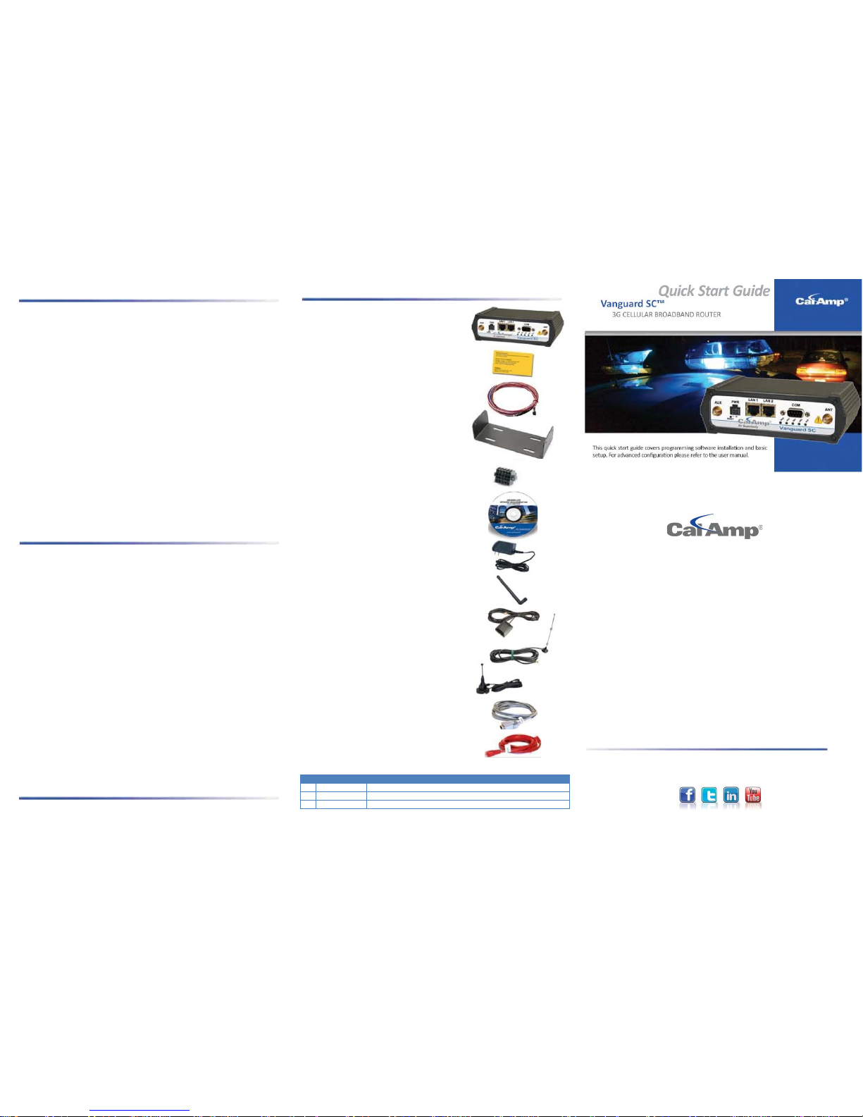
Your package contains:
004-7500-100 (1) CalAmp Information Card
150-7500-004 (1) 6FT DC 3 Wire Power Cable
415-1001-210 (1) 3.5mm 10 Pos I/O Term Socket
817-7010-500 (1) Mounting Plate
If you ordered Vanguard SC Mobile part number:
140-7202-110 Vanguard SC - AT&T HSPA Cellular Router, GPS & WiFi
140-7206-110 Vanguard SC - Generic HSPA Cellular Router, GPS & WiFi
140-7221-110 Vanguard SC - Verizon EVDO Cellular Router, GPS & WiFi
140-7223-110 Vanguard SC - Sprint EVDO Cellular Router, GPS & WiFi
Your package contains:
004-7500-100 (1) CalAmp Information Card
150-7001-002 (1) 22FT Fused Power Cable
415-1001-210 (1) 3.5mm 10 Pos I/O Term Socket
817-2225-900 (1) Mounting Bracket
Accessory Kit
If you ordered Vanguard part number:
250-7200-100 Vanguard Fixed Kit
Your package contains:
002-7200-100 (1) Startup CD with Quick Start Guide
150-7001-005 (1) 110-220VAC 3-Wire Power Supply
401-7500-001 (1) Rubber Duck Swivel SMA Antenna
L2ANT0003 (1) 3W Mag Mount Antenna
L2CAB0002 (1) DB-9 Male to DB-9 Female Serial Cable
L2CAB0006 (1) CAT5 100Base 7' Red Ethernet Cable
If you ordered Vanguard part number:
250-7200-200 Vanguard Mobile Kit
Your package contains:
002-7200-100 (1) Startup CD with Quick Start Guide
150-7001-005 (1) 110-220VAC 3-Wire Power Supply
401-7500-001 (1) Rubber Duck Swivel SMA Antenna
401-7100-003 (1) GPS SMA Mag Mount Antenna
401-7100-004 (1) WiFi 9” Mag Mount Antenna
L2ANT0003 (1) 3W Mag Mount Antenna
L2CAB0002 (1) DB-9 Male to DB-9 Female Serial Cable
L2CAB0006 (1) CAT5 100Base 7' Red Ethernet Cabl e
Minimum Requirements
Interface and configuration of this cellular device requires a user PC with an Ethernet
interface, Microsoft Windo ws 98 or newer, and a web browser.
Vanguard SC Router
CalAmp Information Card
22FT Fused Power Cable
(6FT DC 3 Wire Power Cable for Fix ed model)
Mounting Bracket
(Mounting Plate for Fixed mo del)
3.5 mm 10 Pos I/O Term Socket
Startup CD with Quick Start Guide
110-220VAC-3 Wire Power Supply
Rubber Duck Swivel SMA Antenna
GPS SMA Mag Mount Antenna
WiFi 9” Mag Mount Antenna
3W Mag Mount Antenna
DB-9 Male to DB-9 Female Serial Cable
CATS 100Base 7” Red Ethernet Cable
REVISION HISTORY
REV
DATE
REVISION DETAILS
0
June 2011
Initial release with new part number, PN 004-7200-100.
1
January 2012
Fixed the Dial Settings screen shot and package c ontents list.
A
June 2013
Updated PN 150-7500-004 and Phone Number
Quick Start Guide
Vanguard SC
™
3G CELLULAR BROADBAND ROUTER
© 2011-2013 CalAmp
PN 004-7200-100 Rev. A
Revised June 2013
©
2011-2013 CalAmp
PN 004
-7200-100 Rev. A
All specifications are typical and
subject to change without notice.
CalAmp
1401 N Rice Avenue
Oxnard, CA 93030
US t: 800-992-
7774
507-833-
8819
Int’l t:
+442032874748
+447557133600
www.calamp.com
Page 2
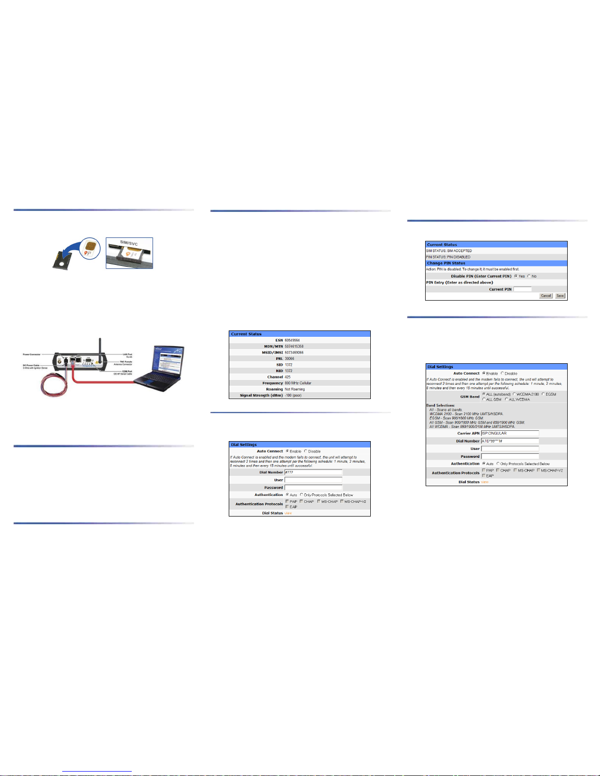
Device Connections
STEP 1 Insert the SIM with the gold side up. Push the card completely into the slot until
it clicks in place. (GSM Users Only).
STEP 2 Connect an antenna(s) to the RF connector. Use of dual band cellular antenna is
preferred.
STEP 3 Connect the Ethernet ca ble to the modem’s Ethernet Port and plug the other end
into the network port of your PC.
STEP 4 Connect the DC Power Cable (or optional AC Power Adapter) to the modem and
plug into a proper power source.
At power up, all LEDs will light red, then amber, then green. Once the boot sequence is
complete, RSSI will light solid green and SVC will be flashing green. Note RSSI flashing
green and SVC amber (indicat es reduced RSSI and/or 2G cell coverage) is suffici ent for
normal operation.
Accessing the Modem’s Web Server
STEP 1 Enable a network connection with the following LAN settings. In the Internet
Protocol (TCP/IP) Properties Window, select Obtain an IP address automatically and
Obtain DNS server address automatically. Click OK and Close.
STEP 2 Open a web browser and enter 192.168.1.50 in the address bar. A login screen
should appear, enter the User name: admin and the Password: password and click OK.
STEP 3 On the device Home page, the PPP status will read DOWN until the cellula r
device is enabled.
Subscriber Activation
In order to use the modem, it must be activated for your specific carrier once the E SN has
been provided for the account. Over-The-Air (OTA) activation is supported and each
carrier has a different procedure.
Provisioning (CDMA Users)
From the device Home page, select Cell Connection from the main navigation panel and
then Provisioning Status. Follow the carrier instructions below.
Sprint PCS Subscribers
Sprint is capable of automatic OMA-DM provisioning. Auto activation is enabled by
default. Apply power and wait 3-4 minutes to verify the Current Status Screen has been
populated with the MDN/MTN and MSID/IMSI numbers. If these numbers do not
populate, your device did not provision properly. Refer to the user manual for Manual
Activation procedures.
Verizon Wireless Subscribers
• Confirm or enter OTASP command: *22899.
• Click the OTASP button.
• Verify CDMA Connection Status has been populated with the MDN/MTN and
MSID/IMSI numbers. If these numbers do not populate, your device did not
provision properly. Refer to the user manual for Manual Activation procedures.
Modem Network Connection
After the modem has been successfully provisioned, a data connection can be enabled. At
the device Home page, select Cell Connection from th e main navigation panel and select
Dial Settings. Select Enable Auto Connect. Click Save.
The SVC LED will indicate when the cellular connection has been established. Steady
green indicates a 3G connection; steady Amber indicates a 2G connection. Return to the
device home page and verify PPP Status is UP. The PPP IP Address shows the current IP
address assigned your device.
Your device is ready to browse t he web.
SIM Card Acceptance (GSM Users)
From the device Home page, sel ect Cell Connection from the main navigation panel and
then SIM Settings. SIM STATUS should read ACCEPTED.
Modem Network Connection
Once the SIM card has been accepted, a data connection can be enabled.
From the device Home page, sel ect Cell Connection from the main navigation panel and
select Dial Settings. Verify the Carrier APN and Dial Number are correct for your provider.
A user name and password may be required. Select Enable Auto Connect and then click
Save.
The SVC LED will indicate when the cellular connection has b een established. Steady
green indicates a 3G connection; steady Amber indicates a 2G connection. Return to the
device home page to verify PPP Status is UP. The PPP IP Address shows the current IP
address assigned your cellular device.
Your device is ready to browse t he web.
 Loading...