

Page 1
VANGUARD 3000™
MULTICARRIER 3G CELLULAR BROADBAND ROUTER
User Manual
Vanguard 3000™ Fixed and Mobile Routers
PN 134732-VG3000 Rev. D
Revised July 2016
Page 2

REVISION HISTORY
REV
DATE
REVISION DETAILS
A
May 2015
Initial release. Part number VG134732-VG3000.
B
February 2016
Clarified I/O Names, added I/O Electrical Characteristics Table. Updated
with changes to latest firmware release.
C
March 2016
Updated WLAN > Access Point and added Security > OpenVPN.
D
July 2016
R16 Updates
Page 3

Copyright Notice
© 2011-2016 CalAmp. All rights reserved.
CalAmp reserves the right to modify the equipment, its specification or this manual without prior notice, in the interest
of improving performance, reliability, or servicing. At the time of publication all data is correct for the operation of the
equipment at the voltage and/or temperature referred to. Performance data indicates typical values related to the
particular product. Product updates may result in differences between the information provided in this manual and the
product shipped. For access to the most current product documentation and application notes, visit www.calamp.com.
No part of this documentation or information supplied may be divulged to any third party without the express written
consent of CalAmp. Products offered may contain software which is proprietary to CalAmp. The offer or supply of these
products and services does not include or infer any transfer of ownership.
Modem Use
The Vanguard Series modems are designed and intended for use in fixed and mobile applications. “Fixed” assumes the
device is physically secured at one location and not easily moved to another location. Please keep the cellular antenna
at a safe distance from your head and body while the modem is in use.
Regulatory Statements
Note: This equipment has been tested and found to comply with the limits for a Class B digital device, pursuant to part
15 of the FCC Rules. These limits are designed to provide reasonable protection against harmful interference in a
residential installation. This equipment generates, uses and can radiate radio frequency energy and, if not installed and
used in accordance with the instructions, may cause harmful interference to radio communications. However, there is
no guarantee that interference will not occur in a particular installation. If this equipment does cause harmful
interference to radio or television reception, which can be determined by turning the equipment off and on, the user is
encouraged to try to correct the interference by one or more of the following measures: i) Reorient or relocate the
receiving antenna. II) Increase the separation between the equipment and receiver. III) Connect the equipment into an
outlet on a circuit different from that to which the receiver is connected. Iv) Consult the dealer or an experienced
radio/TV technician for help.
This device complies with Industry Canada license-exempt RSS standard(s). Operation is subject to the following two
conditions: (1) this device may not cause interference, and (2) this device must accept any interference, including
interference that may cause undesired operation of the device.
Le présent appareil est conforme aux CNR d'Industrie Canada applicables aux appareils radio exempts de licence.
L'exploitation est autorisée aux deux conditions suivantes : (1) l'appareil nedoit pas produire de brouillage, et (2)
l'appareil doit accepter tout brouillage radioélectrique subi, même si le brouillage est susceptible d'en compromettre le
fonctionnement.
Under Industry Canada regulations, this radio transmitter may only operate using an antenna ofa type and maximum
(or lesser) gain approved for the transmitter by Industry Canada. To reduce potential radio interference to other users,
the antenna type and its gain should be so chosen that the equivalent isotropically radiated power (e.i.r.p.) is not more
than that necessary for successful communication.
Conformément à la réglementation d'Industrie Canada, le présent émetteur radio peut fonctionner avec une antenne
d'un type et d'un gain maximal (ou inférieur) approuvé pour l'émetteur par Industrie Canada. Dans le but de réduire les
risques de brouillage radioélectrique à l'intention des autres utilisateurs, il faut choisir le type d'antenne et son gain de
sorte que la puissance isotrope rayonnée équivalente (p.i.r.e.) ne dépasse pas l'intensité nécessaire à l'établissement
d'une communication satisfaisante.
Vanguard 3000 Series Multicarrier Cellular Data Modem & IP Router PN 134732-VG3000 Rev. D| Page i
Page 4

IC ICES-003 Standard Compliance Notice:
When operating at elevated temperature extremes, the surface may exceed +70 Celsius. For user safety,
the Vanguard should be installed in a restricted access location.
WARNING — EXPLOSION HAZARD, do not connect while circuit is live unless area is known to be nonhazardous.
CAN ICES-3 (B)/NMB-3(B)
Important
Maintain a distance of at least 20 cm (8 inches) between the transmitter antenna and any person while in use. This
modem is designed for use in applications that observe the 20 cm separation distance.
Interference Issues
Avoid possible radio frequency (RF) interference by following these guidelines:
The use of cellular telephones or devices in aircraft is illegal. Use in aircraft may endanger operation and
disrupt the cellular network. Failure to observe this restriction may result in suspension or denial of cellular
services to the offender, legal action, or both.
Do not operate in the vicinity of gasoline or diesel fuel pumps unless use has been approved or authorized.
Do not operate in locations where medical equipment that the device could interfere with may be in use.
Do not operate in fuel depots, chemical plants, or blasting areas unless use has been approved and
authorized.
Use care if operating in the vicinity of protected personal medical devices, i.e., hearing aids and pacemakers.
Operation in the presence of other electronic equipment may cause interference if equipment is incorrectly
protected. Follow recommendations for installation from equipment manufacturers.
Mobile Application Safety
Do not change parameters or perform other maintenance of the Vanguard 3000 while driving.
Road safety is crucial. Observe National Regulations for cellular telephones and devices in vehicles.
Avoid potential interference with vehicle electronics by correctly installing the Vanguard 3000 modem.
CalAmp recommends installation by a professional.
UL Listed models only
Vanguard 3000 Series Multicarrier Cellular Data Modem & IP Router PN 134732-VG3000 Rev. D| Page ii
Page 5

TAB LE OF CONTENTS
1 Product Overview ........................................................................................................................... 1
1.1 Module Identification ............................................................................................................................................ 1
1.2 Features and Benefits of the Vanguard Multicarrier Cellular Router .................................................................... 2
1.2.1 ODP (Open Developer Platform) .................................................................................................................. 2
1.3 General Specifications ............................................................................................................................................ 3
1.4 Mechanical Specifications ...................................................................................................................................... 4
1.5 Order Information .................................................................................................................................................. 5
1.5.1 Mounting Brackets ........................................................................................................................................ 5
1.5.2 Accessories ................................................................................................................................................... 6
1.6 External Connectors ............................................................................................................................................... 8
1.7 Antenna ................................................................................................................................................................ 10
1.8 Power Cable Pinout .............................................................................................................................................. 10
1.9 RS-232 RS-485 Serial Port Integration Parameters .............................................................................................. 10
1.10 Reset Button ........................................................................................................................................................ 11
2 Getting Started .............................................................................................................................. 12
2.1 Package Contents ................................................................................................................................................. 12
2.2 Device Connections .............................................................................................................................................. 12
2.3 LAN Configuration ................................................................................................................................................ 13
2.4 Cellular Connections ............................................................................................................................................ 14
2.4.1 GSM Users................................................................................................................................................... 14
2.4.2 CDMA Users ................................................................................................................................................ 14
3 Vanguard Web Interface ............................................................................................................... 14
3.1 Unit Status ............................................................................................................................................................ 16
3.1.1 Status .......................................................................................................................................................... 16
3.1.2 System ........................................................................................................................................................ 19
3.1.3 Basic Settings .............................................................................................................................................. 21
3.2 Cell Connection .................................................................................................................................................... 22
3.2.1 Carrier ......................................................................................................................................................... 22
3.2.2 Settings ....................................................................................................................................................... 25
3.2.3 Dynamic DNS .............................................................................................................................................. 28
3.2.4 System Monitor .......................................................................................................................................... 29
3.3 LAN Settings ......................................................................................................................................................... 31
3.4 WLAN Settings ...................................................................................................................................................... 33
3.4.1 Status .......................................................................................................................................................... 33
3.4.2 Access Point ................................................................................................................................................ 34
3.4.3 Client ........................................................................................................................................................... 36
Vanguard 3000 Series Multicarrier Cellular Data Modem & IP Router PN 001-7300-100 Rev. D| Page iii
Page 6

3.5 Router .................................................................................................................................................................. 38
3.5.1 Port Forwards ............................................................................................................................................. 39
3.5.2 DMZ Support ............................................................................................................................................... 40
3.5.3 IP Filtering ................................................................................................................................................... 41
3.5.4 MAC Filtering .............................................................................................................................................. 44
3.5.5 Static Routes ............................................................................................................................................... 44
3.5.6 ARP .............................................................................................................................................................. 46
3.6 Security ................................................................................................................................................................ 49
3.6.1 Status .......................................................................................................................................................... 49
3.6.2 PPTP ............................................................................................................................................................ 51
3.6.3 IPsec ............................................................................................................................................................ 52
3.6.4 GRE.............................................................................................................................................................. 55
3.6.5 OpenVPN..................................................................................................................................................... 56
3.7 Serial .................................................................................................................................................................... 59
3.7.1 External Serial ............................................................................................................................................. 59
3.8 GPS/GNSS ............................................................................................................................................................. 61
3.8.1 Status .......................................................................................................................................................... 62
3.8.2 Settings ....................................................................................................................................................... 63
3.9 Diagnostics ........................................................................................................................................................... 67
3.9.1 SMS ............................................................................................................................................................. 67
3.9.2 RSSI Traps .................................................................................................................................................... 69
3.9.3 Syslog Settings ............................................................................................................................................ 70
3.9.4 System Log .................................................................................................................................................. 71
3.9.5 Kernel Log ................................................................................................................................................... 72
3.10 I/O Settings .......................................................................................................................................................... 72
3.10.1 Status .......................................................................................................................................................... 72
3.10.2 SNMP .......................................................................................................................................................... 74
3.10.3 Settings ....................................................................................................................................................... 76
3.10.4 Labels .......................................................................................................................................................... 78
3.11 Admin ................................................................................................................................................................... 79
3.11.1 Access ......................................................................................................................................................... 79
3.11.2 Remote Server App ..................................................................................................................................... 81
3.11.3 Remote AdMin ............................................................................................................................................ 82
3.11.4 Radius ......................................................................................................................................................... 83
3.11.5 Firmware Update ........................................................................................................................................ 84
3.11.6 SYstem Reset .............................................................................................................................................. 86
4 IP Addressing ................................................................................................................................. 86
4.1 Overview .............................................................................................................................................................. 86
4.2 IP Addressing Tutorial .......................................................................................................................................... 86
4.3 Private Versus Public IP Addresses ...................................................................................................................... 87
4.4 Port Forwarding ................................................................................................................................................... 87
4.5 DMZ ...................................................................................................................................................................... 88
4.6 Friendly IP Address ............................................................................................................................................... 88
Vanguard 3000 Series Multicarrier Cellular Data Modem & IP Router PN 134732-VG3000 Rev. D| Page iv
Page 7

5 IPsec and VPN Pass-Through Deployment Guide ......................................................................... 89
5.1 Benefits of IPsec ................................................................................................................................................... 89
5.2 Configuration Summary ....................................................................................................................................... 89
5.2.1 Case #1: Vanguard Configured IPsec Client ................................................................................................ 90
5.2.2 Case #2 Vanguard Configured to use a DMZ for VPN Pass-Through .......................................................... 94
6 User I/O Port ................................................................................................................................. 95
6.1 Electrical Characteristics ...................................................................................................................................... 96
6.2 Input Circuit for Analog Inputs ............................................................................................................................. 97
6.3 Simplified Circuit for Digital Input ........................................................................................................................ 97
6.4 Simplified Circuit for Open Collecter Outputs ...................................................................................................... 97
APPENDIX A — Abbreviations and Definitions ............................................................................. 98
APPENDIX B — Mechanical Specifications ..................................................................................... 100
APPENDIX C — UL Installation Instructions ................................................................................... 104
APPENDIX D — NMEA I/O Agent ................................................................................................ 106
6.5 Specifications ..................................................................................................................................................... 106
6.6 PDU Types .......................................................................................................................................................... 109
APPENDIX E Service and Support And Warranty Statement ......................................................... 112
6.7 Warranty Statement .......................................................................................................................................... 114
Vanguard 3000 Series Multicarrier Cellular Data Modem & IP Router PN 134732-VG3000 Rev. D| Page v
Page 8

1 PRODUCT OVERVIEW
Figure 1: Fixed model identification label
Figure 2: Mobile model identification label
The Vanguard 3000™ Router from CalAmp — simple, reliable wireless connectivity without limitations – GSM and
CDMA connectivity in a single device.
Uniquely designed for operation on both GSM and CDMA networks, Vanguard router offers more choice and
redundancy in carrier networks. This single, flexible platform addresses a variety of wireless communications needs
with serial to IP conversion, over-the-air configuration and system monitoring for optimal connectivity. This ready to
deploy broadband router enables wireless data connectivity for up to two LAN and one serial device over public cellular
networks at 3G speeds.
Equipped for a broad range of fixed applications, Vanguard router provides reliable connectivity for Programmable
Logic Controllers (PLCs), Remote Terminal Units (RTUs), Ethernet web cameras or any other Ethernet or serial device.
For mobile applications, this intelligent broadband router incorporates an optional highly sensitive 16-channel GPS
receiver and an intelligent algorithm that offers outstanding receive sensitivity and improved accuracy, integrity and
availability of GPS signals. An optional, built-in Wi-Fi access point also allows your tethered devices to remain
connected even when you leave the vehicle.
This widely deployed wireless solution delivers countless software capabilities. OEMs may tailor the Vanguard router
by loading their application on the Open Developer Platform (ODP) which allows a Linux application to run on a
partition of the embedded flash memory.
1.1 M ODULE IDENTIFICATION
The module identification label can be found on the bottom of your Vanguard router. This label contains the product
part number, the serial number, FCC and IC IDs as well as carrier-specific information that will be required when
activating your data account.
Vanguard 3000 Multicarrier Cellular Data Modem & IP Router PN 134732-VG3000 Rev. D| Page 1
Page 9

1.2 FEATURES AN D BENEFITS OF T HE VAN GUARD MULTIC ARRIE R CEL LULAR R OUTER
Multiple carriers in a single device
Supports dynamic or static IP
Inbound and outbound Ethernet routing
DHCP server and Inbound port mapping/translation (Port Forwarding)
Firewall configuration for increased network security
Diversity antenna port/auxiliary port for increased receive sensitivity
Local or remote configuration using HTTPS secure web server
TCP/IP packet assembler and disassembler for serial connected devices
Inbound IP termination with static IP
Modem domain names with dynamic DNS
Embedded Linux on ARM Cortex-A9 processor
Internet access and web browsing via Ethernet connector
VPN support
On board “2FF” mini-SIM socket (Active only when GSM carrier is selected)
ODP – SDK and APIs for application development
Remote Management for router firmware, radio firmware, and configuration
1.2 .1 OD P (OPE N DEVELOPER PL ATFOR M)
This device includes the Open Development Platform (ODP), which permits customers to develop their own Linux
based applications which run on the modem’s ARM Cortex-A9 processor. The customer’s application can utilize the
external serial port, the external I/O port, and is able to transfer data over the cellular WAN using the Linux socket
libraries. The Vanguard firmware also supports an API that allows the customer’s application to access diagnostic data
from the cell module such as connection status and RSSI. More information and support is provided by CalAmp’s
Applications Engineering organization.
Vanguard 3000 Multicarrier Cellular Data Modem & IP Router PN 134732-VG3000 Rev. D| Page 2
Page 10

1.3 GENERAL SPE CIFIC ATIONS
Interface Connectors
RS-232 / RS-485 DE-9S Connector (DCE female)
10/100 Base-T Full Duplex (Dual)
22 Pin I/O Port
Mini USB Service port — provided for convenience when upgrading cell module only.
Power Connector
Molex 43045-4000 MicroFit 3.0, 4 pin header with Ignition Sense input
LED Indicators
RSSI, SVC, NET, GPS, AUX
Antenna Interface
Primary Antenna 50-ohm SMA Female
Diversity Antenna 50-ohm SMA Female
GPS Antenna (Mobile only) 50-ohm, 3.3V SMA Female
Wi-Fi Antenna (Mobile only) 50-ohm RP-SMA Female
Size
4.5 (L) x 6.0 (W) x 1.9(H) inches (11.4 x 15.2 x 4.8 cm)
Weight
1.94lb (0.88 kg)
Power Input
9-32 VDC
Maximum TX Power
CDMA 25 dBm
GSM/EDGE 33 dBm
UMTS 24 dBm
Rx Sensitivity
CDMA >-107 dBm
GSM/EDGE >-105 dBm
UMTS >-109 dBm
Frequencies
Cellular: TX: 824-849 MHz; Rx: 869-894 MHz
PCS: TX: 1850-1910 MHz; Rx: 1930-1990 MHz
Temperature
Operating: -30°C to +70°C 100% duty cycle. Note: Cellular TX power may be reduced
outside this range; Storage: -40° to +85°C (-40° to +185°F)
Emissions
FCC Part 15b FCC IDs APV-55BTW and QIP-PXS8
Transport Protocols
UDP/TCP
Command Protocol
Web Interface
Product specifications are subject to change without notice.
Vanguard 3000 Multicarrier Cellular Data Modem & IP Router PN 134732-VG3000 Rev. D| Page 3
Page 11
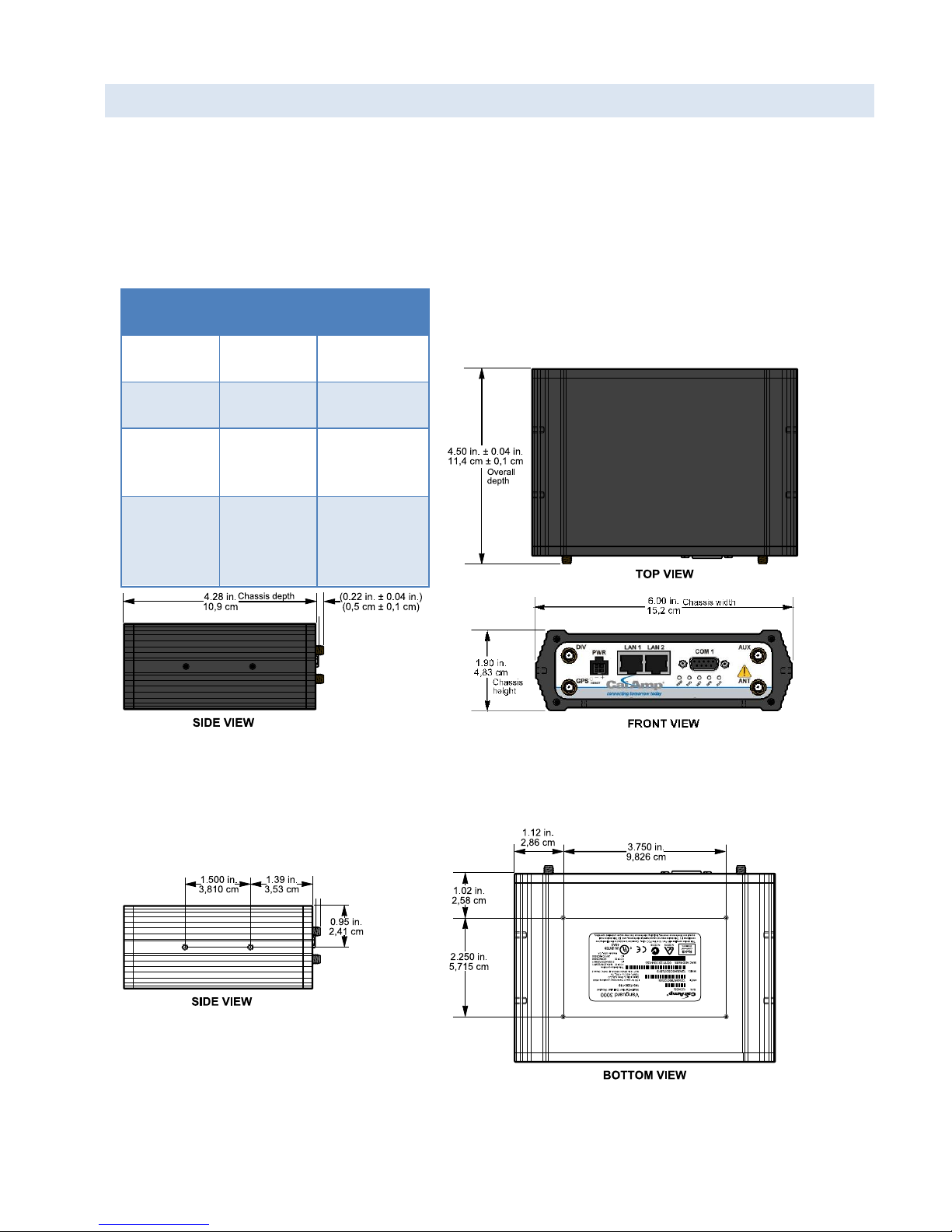
1.4 M ECHANICAL SPE CIFICAT IONS
Table 1: Vanguard router chassis overall dimensions
Dimension
Inches
Centimeters
Height
1.90
4,83
Width
6.00
15,2
Depth
(Overall)
4.50 ± 0.04
11,4 ± 0,1
Depth
(Chassis
only)
4.28
10,9
Figure 3: Vanguard router chassis overall dimensions. Same mounting holes (not shown)
dimension as on bottom side of Chassis.
Figure 4: Side tapped mounting hole location detail —
typical both sides.
#8-32 UNC – 2B thread × 0.30 in. (0,76 cm)
depth
2 holes for mounting both sides (4 holes total).
Figure 5: Base tapped mounting hole location detail — bottom of chassis. Same dimension on
top side of Chassis.
#6-32 UNC – 2B thread × 0.12 in. (0,30 cm) depth
4 holes for base mounting.
The following table and figure show overall dimensions of the Vanguard router for fixed and mobile models. (Both
models have the same dimensions and differ only slightly in appearance: the fixed model has only two antenna
connectors in the front of the unit, where the mobile model has four.) Dimensioned drawings of units with mounting
brackets are provided in 0. The drawings and associated data may be used for layout reference, but it is advised that a
physical comparison be made to the modem and bracket before laying out and drilling mounting holes.
Vanguard 3000 Multicarrier Cellular Data Modem & IP Router PN 134732-VG3000 Rev. D| Page 4
Page 12
1.5 O RDER INFOR MATIO N
Router
Model Part Number
Vanguard 3000TM Fixed
VG3000-PXS-F
Vanguard 3000
TM
Mobile
VG3000-PXS-M
Application
Bracket
Part Number / Description
Fixed
817-7010-500
Flat plate
(fastens to the top or bottom of
the Vanguard chassis)
Mobile
817-2225-900
U-bracket
(fastens to the sides of Vanguard
chassis for top or bottom
mounting)
The following table shows the available order options and part numbers required for ordering Vanguard routers.
Table 2: Vanguard Router Order Information
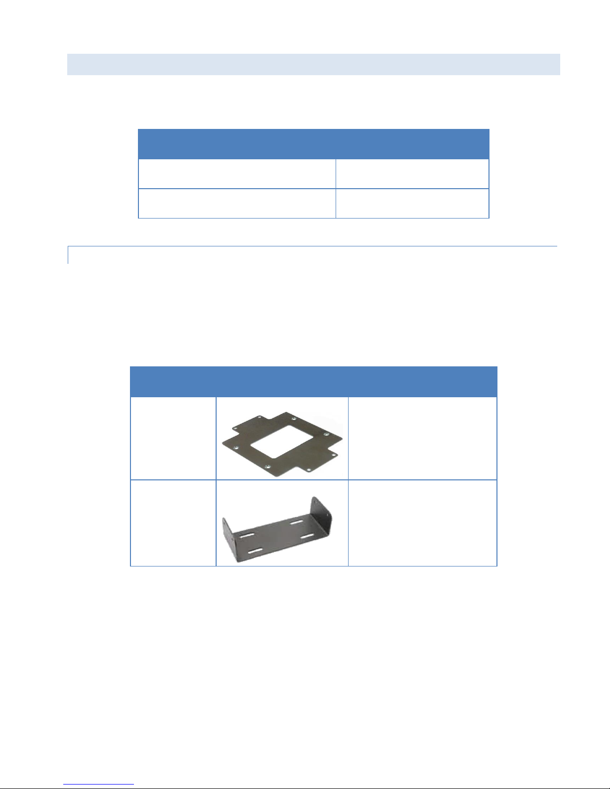
1.5 .1 MO UNTING BRACKETS
A mounting bracket is provided with each Vanguard 3000. The type of bracket provided is determined by the typical
mounting method for each application.
For fixed-location applications, a flat-plate bracket provides for low-profile, space-saving mounting.
For mobile applications, a U-shaped bracket is provided to allow mounting flexibility.
Table 3: Vanguard Mounting Brackets
Four screws are provided with each bracket to fasten the bracket to the body of the Vanguard router.
Fixed — Four #6-32 × ¼ (3/16-inch thread length) clear-zinc plated stainless steel Philips undercut flat head
(82° countersink) screws are provided to fasten the flat-plate mounting bracket to the Vanguard chassis.
Mobile — Four #8-32 × ½ (3/8-inch thread length) black plated stainless steel slotted hex flange head cap
screws are provided to fasten the U-bracket at the sides of the Vanguard chassis for mounting.
Vanguard 3000 Multicarrier Cellular Data Modem & IP Router PN 134732-VG3000 Rev. D| Page 5
Page 13
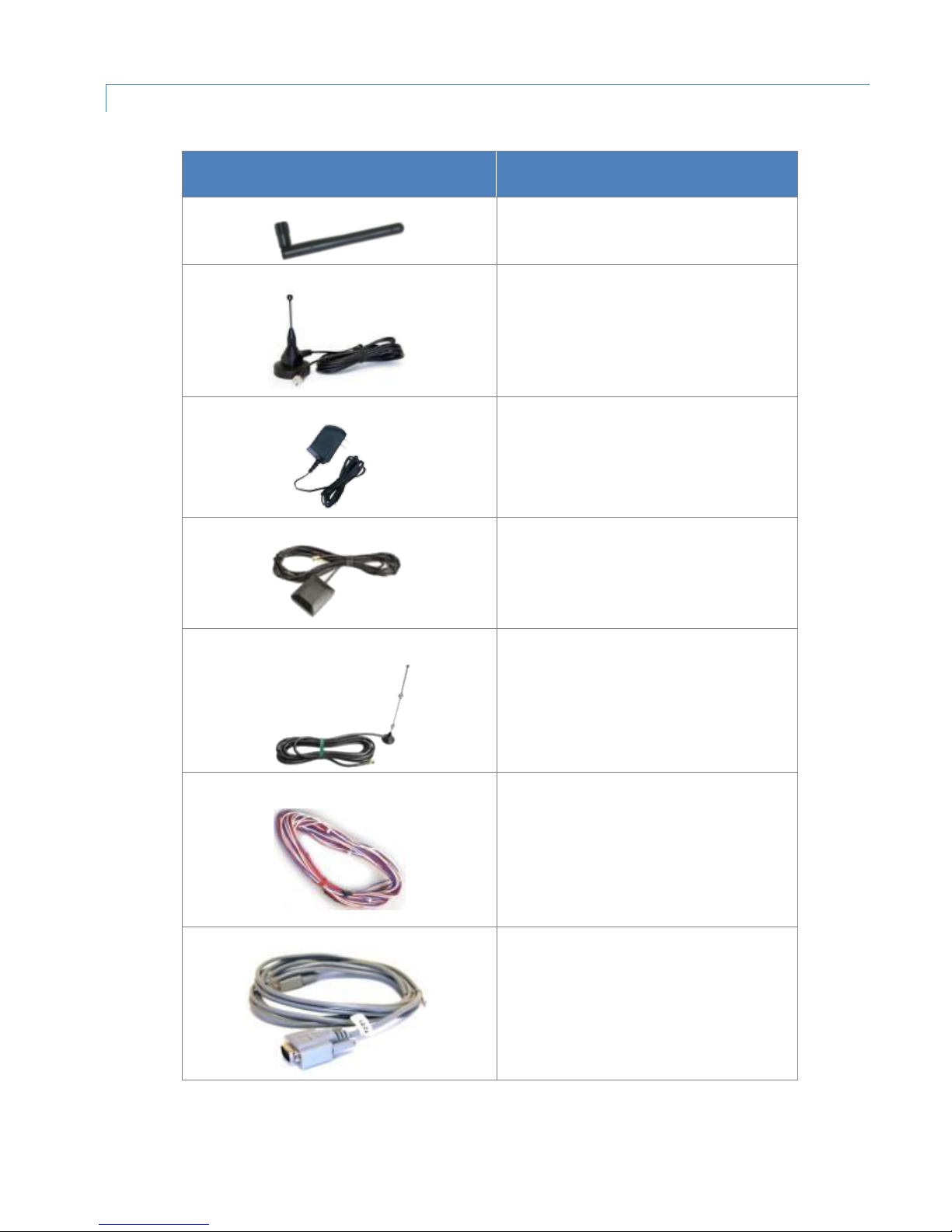
1.5 .2 ACCESS ORIES
Accessory
Part Number / Description
401-7500-001
4" plastic “Rubber Duck” style Antenna
L2ANT0003
3" Mag Mount Antenna
150-7001-005
110 VAC Input Power
401-7100-003
GPS SMA Mag-Mount Antenna
401-7100-004
Wi-Fi Mag-Mount Antenna
150-7001-002
22' DC Power Cable w/ inline fuse (Mobile
models)
150-7500-004
6' DC 3-wire Power Cable (Fixed models)
L2CAB0002
DE-9 Serial Cable
Table 4: Vanguard router Accessories
Vanguard 3000 Multicarrier Cellular Data Modem & IP Router PN 134732-VG3000 Rev. D| Page 6
Page 14

Accessory
Part Number / Description
L2CAB0006
7' Ethernet Cable
250-5800-410
DIN Rail Mount — kit includes DIN mounting
plate assembly (with retainer spring and
screw), four #6-32 × ¼-inch length cap
screws and four #6 lock washers for
fastening to bottom of Vanguard chassis.
Vanguard 3000 Multicarrier Cellular Data Modem & IP Router PN 134732-VG3000 Rev. D| Page 7
Page 15
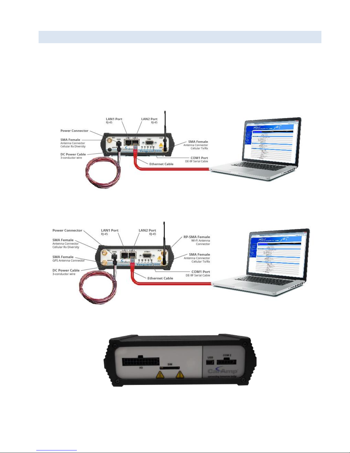
1.6 E XTERN AL CONNECT ORS
This section describes the external connectors for the Vanguard router.
Figure 6 shows the front panel connections for standard fixed models.
Figure 7 shows the front panel connections for Mobile models with GPS and Wi-Fi.
Figure 8 shows the rear panel for all models.
Figure 6: Front panel — Standard Fixed models
Figure 7: Front panel — Mobile models with GPS and Wi-Fi
Figure 8: Rear panel connections
Vanguard 3000 Multicarrier Cellular Data Modem & IP Router PN 134732-VG3000 Rev. D| Page 8
Page 16

Table 5: External connectors
Panel
Indicators
Connection
Description
COM 1
RS-232 / RS-485
Serial to IP conversion use
ANT
SMA
Primary RF Antenna
DIV
SMA
Cellular Diversity Antenna
AUX (Figure 7)
RP-SMA
Wi-Fi antenna
GPS (Figure 7)
SMA
GPS Antenna
LAN 1, LAN 2
RJ-45
Interface for Ethernet connection to devices
USB
USB Mini
Available for diagnostic use.
RESET
Depress switch to reset router. Press and hold during boot
to revert settings to factory defaults.
PWR Jack
Molex 43025-0400 receptacle for
four-pin power plug with optional
ignition sense
Bottom pins: +9-28VDC power (pin 1) and ground (pin 2)
Top pins: optional ignition-sense (3) and not connected (4).
See diagram for compatible cable on the following page.
SIM/SVC
SIM Card socket
Interface for SIM card (Mini-SIM “2FF” form factor). Your
wireless service provider will supply the SIM card with your
wireless service contract.
COM 2
Molex 43650-0501 receptacle for 5pin RS-232 TTL adapter 5-Pin TTL
Serial Port
Available for diagnostic use. Serial port – Level conversion
cable required.
Function
Off
Green
Flash Green
Red
Flash Red
Amber
Flash Amber
RSSI Strong
Weak/None
Medium
SVC 3G/4G
3G/4G/NC
NC
2G
2G/NC
NET
No
connectivity
Rx data
Tx data
Rx/Tx
GPS
Disabled
Fix
Search
No fix
AUX
Disabled
Good
Failed
Table 6: Status LEDs
If SVC is solid, then the modem is connected to the cellular network. If it is flashing, the modem is trying to
connect to the network.
AUX refers to Wi-Fi in mobile models.
The behavior of the LEDs is different than the table at boot. The boot sequence is: all red, all off, all amber, all green, all
flash green three times, and then the boot sequence is complete.
Vanguard 3000 Multicarrier Cellular Data Modem & IP Router PN 134732-VG3000 Rev. D| Page 9
Page 17
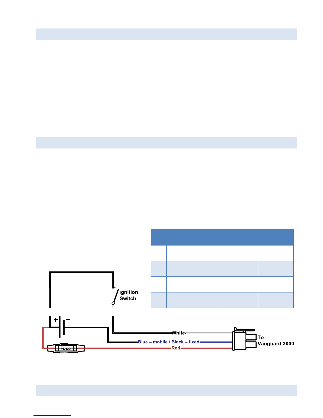
1.7 ANTENNA
Figure 9: Wiring for Ignition sense
Table 7: Power Cable pin-out, signal, and wire colors
Pin
Signal
Color Mobile
Color Fixed
1
V
IN
/ V
Batt
= 9 to 28 VDC
Red
Red 2 Ground
Blue
Black
3
Ignition Sense
White
White
4
No Connect
NA
NA
Primary cellular antenna connections are SMA female connectors and must be used with antenna with SMA male
connectors. When using a direct mount or rubber duck antenna, choose the antenna specific to your band
requirements. Mounting options and cable lengths are user’s choice and application specific.
The diversity antenna connector, labeled DIV, can be used for a Diversity antenna. The diversity port supports Cellular
(850 MHz) and PCS (1900 MHz) bands. Connect a dual band cellular antenna to this port to implement RX diversity on
the unit and increase receive sensitivity on the cellular network.
For mobile models equipped with Wi-Fi, the antenna connector labeled AUX is an RP-SMA female connector for 2.4
GHz Wi-Fi that facilitates 802.11 b and 802.11 g wireless networks.
1.8 P OWER CABLE PINOUT
Depending on the version (fixed or mobile) of Vanguard router ordered, different power cables are provided. The
mobile version ships with a 22-foot power cable that requires a fuse (included). The fixed version ships with a 6 foot DC
three-wire power cable that does not contain a fuse. An AC power adapter is available as an optional accessory.
Regardless of the cable length, the pinout is the same and only the color of the ground wire differs (blue in the mobile
wire harness, and black in the fixed).
When installed for a fixed application or if the Ignition-sense line is not required in a mobile application, the ignition
sense line (white wire) should be shorted to VIN / V
(red wire).
Batt
The fuse provided inside the fuse-holder that is part of the wiring for mobile applications is a 2 Amp fast-acting fuse
(EF2AL250VP).
1.9 RS-232 RS-485 SERIAL PORT INTEG RATION PARAME TERS
Vanguard 3000 Multicarrier Cellular Data Modem & IP Router PN 134732-VG3000 Rev. D| Page 10
Page 18
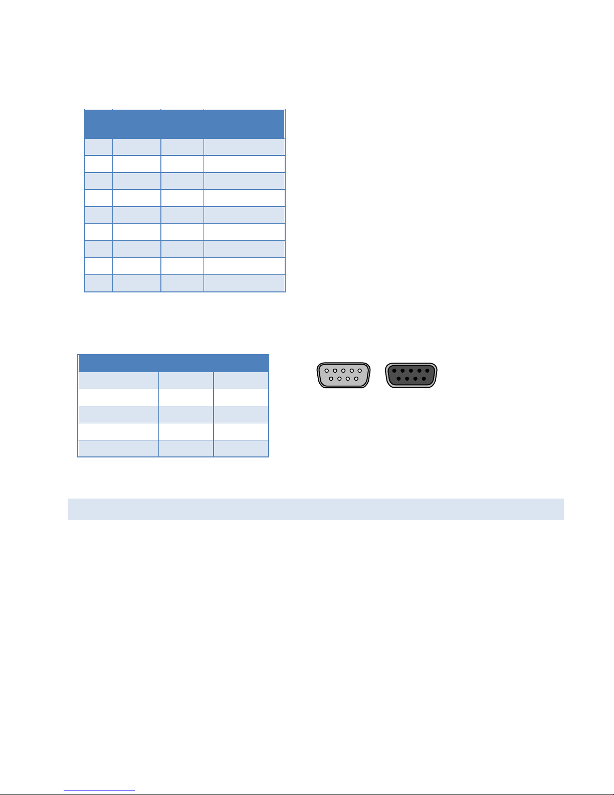
Table 8 provides the serial cable design information to integrate the Vanguard modem into your system. Table 9 gives
Table 8: Standard RS-232/RS-485 DE-9 Pinout
Pin
RS-232
Signal
RS-485
Signal
Direction
1
DCD
--
← (Out)
2
RXD
RXP
←(Out)
3
TXD
TXP
→(In)
4
DTR
--
→(In)
5
GND
-- 6
DSR
--
←(Out)
7
RTS
TXN
→(In)
8
CTS
RXN
← (Out)
9
RI*
5V
←(Out)
Table 9 Default RS-232 / RS-485 Communications
Parameters
Parameter
Value
Bits Per Second
115,200
Data Bits
8 Parity
None
Stop Bits
1 Flow Control
None
Figure 10: DE-9 Connectors
1 15 5
6 9 9 6
Male Female
the default RS-232 / RS-485 communication parameters.
*Always asserted
1.1 0 RESET BU TTON
The RESET button can be used to return the Vanguard to its factory default settings. Power-on the unit then promptly
press-and-hold the RESET button. The LEDS will cycle through all red, all off, all amber, all green. During the all green
phase, the RSSI LED will turn red to show that the configuration is being reset to defaults. Once the LEDs flash all green
3 times, release the RESET button and proceed as normal.
Vanguard 3000 Multicarrier Cellular Data Modem & IP Router PN 134732-VG3000 Rev. D| Page 11
Page 19

2 GE TTING START ED
2.1 P ACKAGE CONTENTS
Vanguard Router
Power Cable
22 Pin I/O Cable
Mounting bracket
Quick-Start Guide
2.2 D EVICE CONNECTIO NS
1. (GSM users) Insert the SIM card into the spring-loaded SIM slot as shown.
Figure 11: Insert SIM card into SIM slot
2. Connect a cellular antenna (for Tx/Rx) to the female SMA connector labeled ANT on the front of the Vanguard
modem. Optionally, a second cellular antenna may be connected to the female SMA connector labeled DIV on
the front panel of the Vanguard modem for Rx diversity.
Note: Use of dual band cellular antennas is preferred.
3. For Mobile units, Connect a GPS antenna to the SMA connector labeled GPS and connect a Wi-Fi antenna to
the RP-SMA connector labeled AUX.
4. Connect an Ethernet cable into either LAN port and plug the other end into the network port of your PC.
5. Connect the DC power cable (or optional AC power adapter) to an applicable power source and plug the
connector into the modem power (PWR) connector. If using the fused power cable to connect to a DC supply
(car battery), use the diagram in Figure 9: Wiring for Ignition sense and accompanying pin-out information in
Table 7 to connect the unit.
Vanguard 3000 Multicarrier Cellular Data Modem & IP Router PN 134732-VG3000 Rev. D| Page 12
Page 20
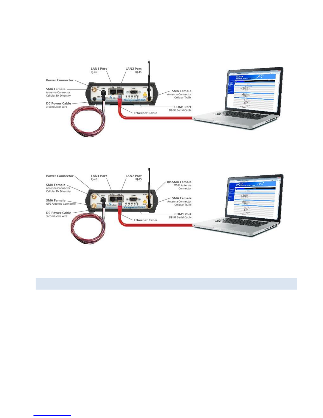
Figure 12: Connect antenna to ANT connector, connect Ethernet cable to either LAN port, and connect power cable
Fixed model
Mobile model
2.3 LAN CONF IGURATION
The Vanguard router is configured via a Web-browser interface and contains a DHCP server which will automatically
assign an IP address to your computer, however in some cases it may be necessary to change the network settings on
your computer to accept the IP address assigned by the Vanguard. Refer to your operating system documentation for
detailed network setup instructions.
Vanguard 3000 Multicarrier Cellular Data Modem & IP Router PN 134732-VG3000 Rev. D| Page 13
Page 21
2.4 CELLUL AR CONNECT IONS
Before you begin, you will need an active Cellular account with the carrier of your choice.
2.4 .1 GSM USERS
Insert the SIM card with the gold side up into the SIM slot in the rear of the device. Push the card completely into the
slot until it clicks in place. If you have already powered your device, you will need to cycle power to register the SIM for
proper operation.
2.4 .2 CD MA US ERS
Refer to Provisioning (CDMA only) to provision your modem for proper operation.
3 VANGUAR D WEB INTERFACE
Figure 13: CalAmp Vanguard Cellular Broadband Router Web Interface banner
Start your Web browser and enter 192.168.1.50 in the address bar. A Web Server Authentication window appears.
Vanguard 3000 Multicarrier Cellular Data Modem & IP Router PN 134732-VG3000 Rev. D| Page 14
Page 22
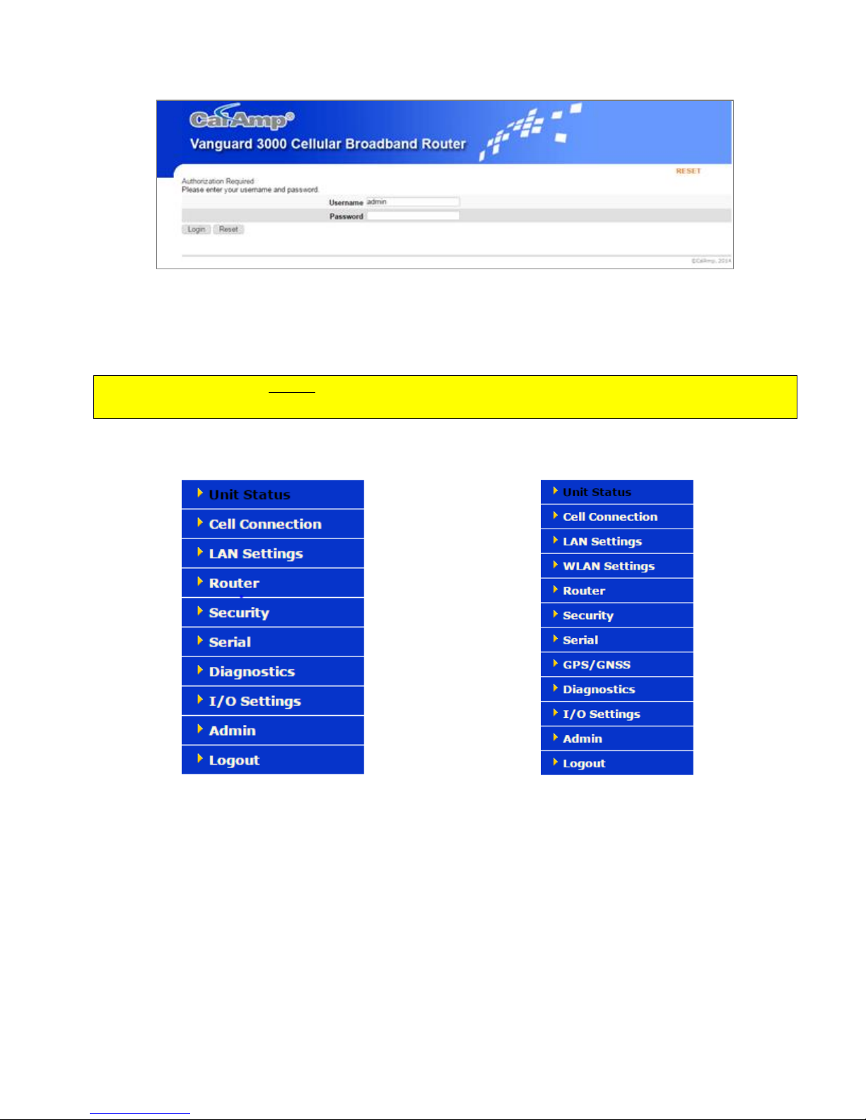
Figure 14: Web Server Authentication window
Figure 15: Main Navigation Pane — Fixed
Figure 16: Main Navigation Pane — Mobile (with GPS and Wi-Fi)
Enter the User Name: admin and the Password: password and click OK to log into the modem’s Home Page. Vanguard
3000 Web interface is divided into two sections. On the left is the main navigation pane (shown in the following
figures). On the right is the content area for the desired page (shown on the following pages).
IMPORTANT NOTE. CalAmp strongly recommends that the default password be changed before the Vanguard is
deployed on a public cellular network.
Note: If the computer you are using has previously been used to set up another CalAmp router at that same IP address,
you may need to delete browser history (specifically, Temporary Internet files) for the pages of the web interface to
display correctly.
If you have a Fixed model, you will not see options in the navigation pane for WLAN Settings or GPS/GNSS, which are
only available for the Mobile model.
Save & Apply and Save
On each screen, you have the option to Save & Apply or Save your configuration changes. Save & Apply commits the
changes to persistent configuration files. Save only stores the changes in the volatile storage, and changes can be
reverted back to the original configuration settings by clicking the Unsaved Changes link at the top of the page and the
Revert button. You can also modify the configuration values in more than one page and commit all the changes with
the Unsaved Changes’ Save & Apply button.
Vanguard 3000 Multicarrier Cellular Data Modem & IP Router PN 134732-VG3000 Rev. D| Page 15
Page 23
3.1 UNIT S TATUS
The Unit Status is the first page displayed when navigating to the Vanguard 3000 modem Web interface and is the
default page. Select Unit Status from the left navigation pane to return to this page. From this page, you can view
Status, System information or access Basic Settings.
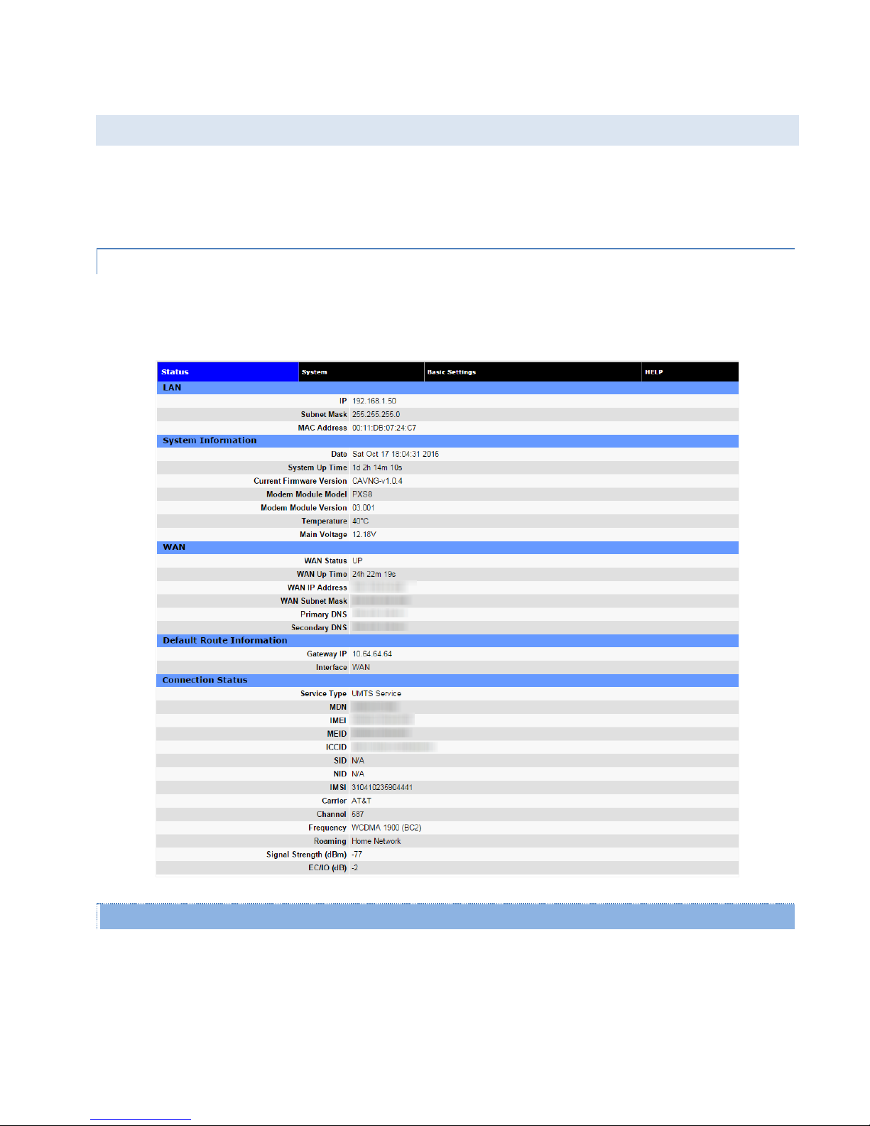
3.1 .1 STATUS
Some Connection Status fields may not display depending on GSM or CDMA configuration.
Figure 17: Vanguard 3000 Unit Status (GSM) Status tab
LAN
IP
LAN IP address of this device (the modem).
Subnet Mask
LAN subnet mask for the modem.
Vanguard 3000 Multicarrier Cellular Data Modem & IP Router PN 134732-VG3000 Rev. D| Page 16
Page 24

MAC Address
Media Access Control Address. Every Ethernet device (i.e. LAN cards) has a unique hardware serial number or
MAC address to identify each Network Device from all others.
System Information
Date
Current date and time (UTC) received from the GPS receiver (Mobile models) or from a time server (see Basic
Settings > Network Time).
System Up time
Uptime in hours, minutes and seconds.
Current Firmware Version
Firmware version currently loaded. Please visit www.calamp.com for the latest updates.
Modem Module Model
Model of the cellular modem installed.
Modem Module Version
Firmware version of the cellular modem.
Temperature
Current internal temperature of the Vanguard 3000.
Main Voltage
System input voltage sensed by the modem.
Default Route Information
Gateway IP
The IP address of the gateway on the cellular network, if provided by the carrier, or the gateway on the Wi-Fi
network, if Wi-Fi Client mode is enabled and a Wi-Fi connection is active.
Interface
The interface (WAN or Wi-Fi) used to reach the Gateway IP.
WAN
WAN Status
Status of the cellular connection, usually UP when connected properly.
WAN IP Address
IP address of the Vanguard, as assigned by the cellular carrier, when WAN is UP.
WAN Subnet Mask
Subnet Mask of the Vanguard, as assigned by the cellular carrier, when WAN is UP.
Vanguard 3000 Multicarrier Cellular Data Modem & IP Router PN 134732-VG3000 Rev. D| Page 17
Page 25

Primary DNS
The Primary DNS server, as assigned by the cellular carrier, when WAN is UP.
Secondary DNS
The Secondary DNS server, as assigned by the cellular carrier, when WAN is UP.
Connection Status
The information displayed in this section will vary depending on the Service Type. The possible options are described
below.
Service Type
Determines the type of network your device has connected to: GPRS, EDGE, HSDPA, HSUPA or HSPA.
"Searching..." will display if the SIM is invalid, missing, or if you need to enter the PIN.
MDN
(Mobile Directory Number) The actual phone number of the device as supplied by the carrier. When the unit
is successfully provisioned, the phone number for the user account will be displayed. The MDN may display
“NOT AVAILABLE” if the PIN status is disabled or the MDN is unknown.
IMEI
The International Mobile Equipment Identity is a unique 15-digit number that serves as the serial number of
the GSM module in the modem.
MEID
The Electronic Serial Number is only applicable for the CDMA product line, and is carrier specific (Verizon,
Sprint, etc.).
ICCID
The Integrated Circuit Card Identifier is the primary account number stored in the SIM.
SID
System ID (Identity), applicable only to CDMA networks, provided by the Carrier.
NID
Network Identifier, applicable only to CDMA networks, as reported by the network.
IMSI
The International Mobile Subscriber Identity is a unique number which designates the subscriber. This number
is used for provisioning in network elements. The IMSI may display “NOT AVAILABLE” if a SIM card is not
detected.
Carrier
Cellular provider name or code. “No SIM or PIN Required" is displayed if the SIM is invalid missing, or if the
correct PIN has not yet been entered.
Vanguard 3000 Multicarrier Cellular Data Modem & IP Router PN 134732-VG3000 Rev. D| Page 18
Page 26
Channel
Cell Site channel number at which the modem is connected and is useful for the carrier in the event of
troubleshooting.
Frequency
Cellular frequency band the modem is using. All U.S. CDMA carriers use 800MHz and/or 1900MHz; GSM/UMTS
carriers in other countries may use 850MHz/900MHz/1800MHz/1900MHZ GSM bands or
800MHz/850MHz/900MHz/1900MHZ/2100MHz bands.
Roaming
Displays Roaming or Not Roaming.
Signal Strength (dBm)
Measured in dBm, this is the Received Signal Strength Indication (RSSI).
EC/IO.
Measured in dBm, EC/IO is a measure of interference. Values closer to 0 indicate weaker interference.
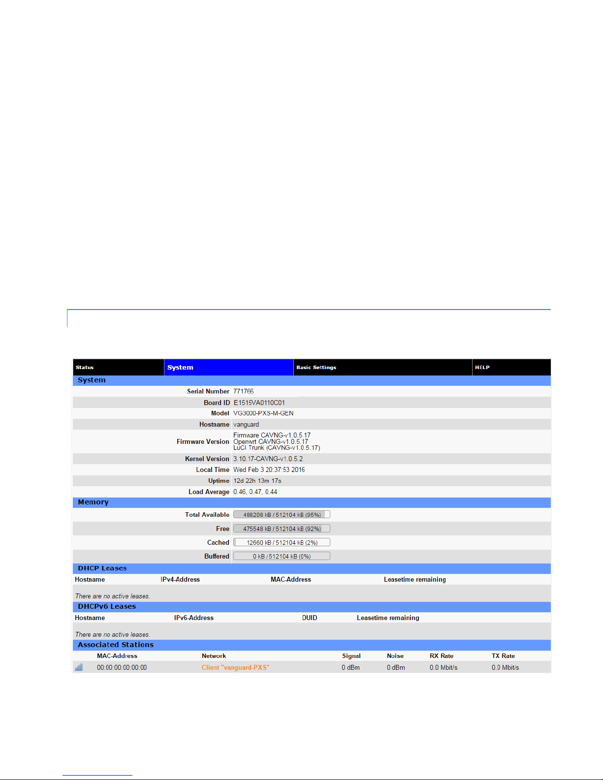
3.1 .2 SYSTEM
Figure 18: Unit Status — System
Vanguard 3000 Multicarrier Cellular Data Modem & IP Router PN 134732-VG3000 Rev. D| Page 19
Page 27

System
Serial Number
The router serial number is a unique ID assigned when the product was built.
Board ID
Unit motherboard identifier.
Model Number
Unit model number defining its capabilities and features.
Hostname
The name of the router provided by the operating system.
Firmware Version
The versions of the top-level component firmware packages in the router OS.
Kernel Version
The version of the Linux kernel in the router OS.
Local Time
The current system time observed by the router. Source may be from the configured NTP server or the GPS
receiver, if installed.
Uptime
The time since the router was last rebooted.
Load Average
The average number of processes in a runnable or non-interruptible state for the past 1, 5, and 15 minutes.
Memory
The current memory usage, broken out into Total Available, Free, Cached and Buffered categories.
DHCP Leases
The list of IPv4 leases given out to clients on the wired or wireless LAN interfaces by the DHCP server.
Associated Stations
Currently bounded Access Point information.
MAC-Address
MAC-address of clients which are connected.
Network
SSID of clients which are connected.
Vanguard 3000 Multicarrier Cellular Data Modem & IP Router PN 134732-VG3000 Rev. D| Page 20
Page 28
Signal
Signal strength of AP.
Noise
The noise level indicates the amount of background noise in the environment.
RX Rate
Rx Rate is the rate at which packets are received from router.
TX Rate
TX Rate is the rate at which packets are sent from router.
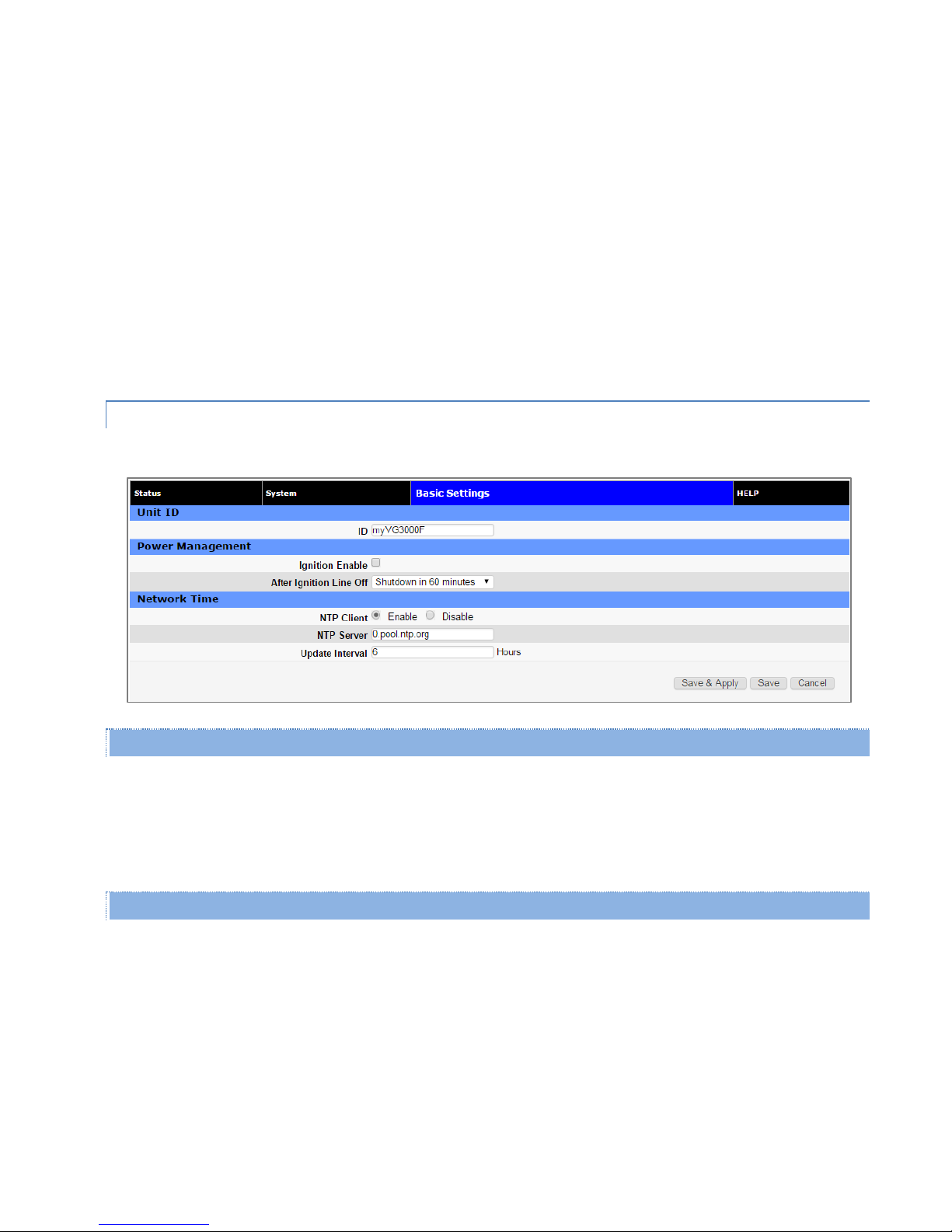
3.1 .3 BASIC S ETTING S
Figure 19: Unit Status — Basic Settings
Unit ID
ID
The identification string serves to distinguish this unit. It is also the TAIP identification for GPS reporting and
serves as the syslocation for the SNMP facility. Unit ID can be up to 32 characters long and can consist of
letters, digits and the underscore ‘_’ character.
Power Management
Depending on power cabling, the Vanguard 3000 may stay ON regardless of whether the vehicle ignition is on. The unit
can be configured to automatically shut down 1, 5, 30, 60, 120 or 240 minutes after ignition has been turned off.
Leaving the unit live allows the driver to use the modem without idling the vehicle and defining a shut-off time limit
prevents the modem from draining the battery when the vehicle is unoccupied.
Ignition Enable
Disabled by default.
After Ignition Line Off
Select a time limit: 1, 5, 30, 60, 120, or 240 minutes.
Vanguard 3000 Multicarrier Cellular Data Modem & IP Router PN 134732-VG3000 Rev. D| Page 21
Page 29

Network Time
The Vanguard 3000 is capable of maintaining the current time (UTC) by synchronizing itself with a Network Time
Protocol (NTP) Server. You may specify a server domain name or IP address and how frequently the router should
synchronize with the server. The router must have DNS access and a route to the internet to synchronize with the
supplied default ntp.org server – this is not always true on private cellular networks. The router does not save or track
time while powered off, so time will be inaccurate until the router can connect with the server, which it does on
startup (in addition to synchronizing according the Update Frequency specified).
NTP Client
Disabled by default. Select Enable to activate the router’s NTP client to synchronize with the specified server.
NTP Server
Enter the domain name or IP address of the desired NTP Server. Most public NTP Servers have a posted usage
policy. A review of usage policies and the choice of an appropriate server is recommended.
Update Interval
Specify the frequency to synchronize the router time with the configured NTP Server. By default,
synchronization is set 24 hour.
3.2 CELL CONNEC TION
Select Cell Connection from the left navigation pane to access the Carrier, Settings, Dynamic DNS and System Monitor
tabs.
3.2 .1 CARRIER
The Carrier tab enables you to configure the carrier (cellular provider) and credentials to be used for data calls. Two
carriers can be configured and either of them chosen to be the active carrier, or you can set parameters for automatic
carrier switching. Depending on the carrier(s) selected, more settings and actions are available in the Settings tab.
Vanguard 3000 Multicarrier Cellular Data Modem & IP Router PN 134732-VG3000 Rev. D| Page 22
Page 30
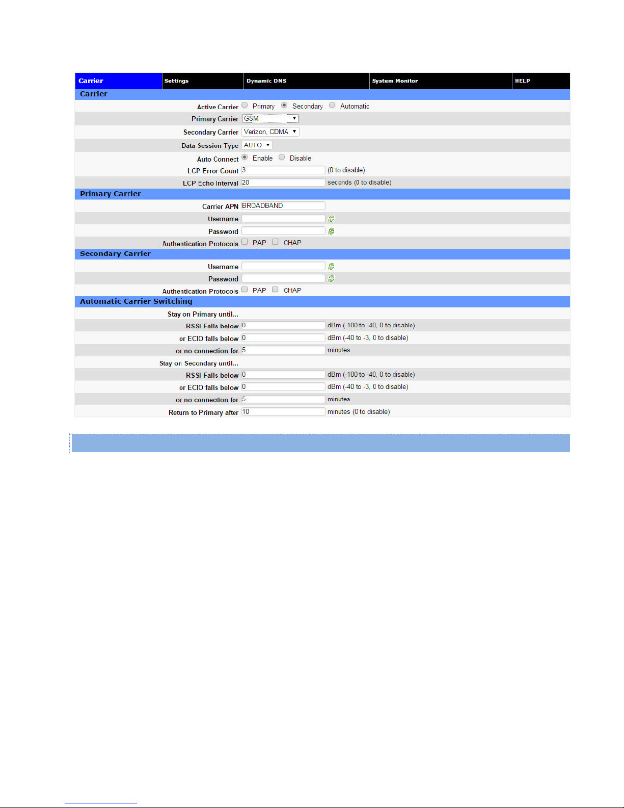
Figure 20: Cell Connection — Carrier
Carrier
Active Carrier
Select which carrier, Primary or Secondary, and credentials to use for carrier connection. Select Automatic to
have the modem choose a carrier based on conditions defined in the Automatic Carrier Switching section at
the bottom of the page.
Primary Carrier
Select the appropriate carrier with cellular protocol (GSM/CDMA) from this list that will serve as the primary
carrier. The Primary Carrier selected cannot be the same as the Secondary Carrier. GSM carriers require that a
proper SIM be installed.
Secondary Carrier
Select the appropriate carrier with cellular protocol (GSM/CDMA) from this list that will serve as the secondary
carrier. This selection cannot be the same as the Primary Carrier. GSM carriers require that a valid SIM be
installed.
Data Session Type
Select the cellular technology used. Options include 2G, 3G or Auto.
Auto Connect
Select Enable (the default and recommended setting), and the modem will automatically dial the connection
Vanguard 3000 Multicarrier Cellular Data Modem & IP Router PN 134732-VG3000 Rev. D| Page 23
Page 31

upon startup, and to attempt reconnection if the connection is lost. Select Disable to prevent the modem
from automatically connecting upon startup. When disabled, a button will be displayed that can be used to
manually connect or disconnect the wireless WAN service.
LCP Error Count/LCP Echo Interval
These options let you define the acceptable error level above which the data link with the cellular carrier is
broken. Link Control Protocol (LCP) echoes are sent at the specified interval to test the link, and the link is
considered broken when the error count exceeds the given number. Select 0 to disable the LCP echo message.
If Auto Connect is enabled and the modem fails to connect, the unit will attempt to reconnect two times and then
make an attempt at one minute, at two minutes, at eight minutes, and then every fifteen minutes until successful.
Primary Carrier / Secondary Carrier (details)
Carrier APN
This field is visible only when the corresponding carrier supports GSM. Enter the APN provided by the carrier.
Username
If your cellular provider requires a user name, enter it here. Leave blank if not required.
Password
If your cellular provider requires a password, enter it here. Leave blank if not required.
Authentication Protocols
Select the authentication protocol used. If no protocol is selected (the default and recommended setting for
most applications), the Vanguard 3000 will try to negotiate a protocol with the cell tower if the cellular carrier
allows negotiation. If either protocol (PAP, CHAP or both) is chosen, then the Vanguard will only offer to
connect using the specified protocol(s), where PAP is Password Authentication Protocol and CHAP is
Challenge-Handshake Authentication Protocol.
― PAP: The Password Authentication Protocol is a pre-shared key method for authenticating with the
cellular provider.
― CHAP: The Challenge-Handshake Authentication Protocol is a two-way authentication scheme
between router and provider.
Note: Normally the cell provider does not require a username or password, in which case leave the User and
Password fields blank. An issue has been identified with SIMs from two carriers (AT&T and Bell Mobility) for
special applications where a username and password are required (which is uncommon but possible). In this
case, it is necessary to select either PAP or CHAP authentication to establish a data connection.
Automatic Carrier Switching
Stay on Primary until
Settings in this section allow you to set parameters so that if the modem is unable to connect to the primary carrier,
sees a low received signal strength or ECIO, or loses connection with the primary carrier for the number of minutes you
specify, the modem will switch to the secondary carrier. The switchover from primary to secondary, or vice versa, will
take 30-60 seconds, during which the device will not have network connectivity.
Vanguard 3000 Multicarrier Cellular Data Modem & IP Router PN 134732-VG3000 Rev. D| Page 24
Page 32

RSSI falls below
If the received signal strength for the primary carrier falls below this number, the modem will switch to the
secondary carrier. Enter the RSSI level threshold for which if the primary carrier connection drops below, the
system will attempt to switch to the secondary carrier. (To disable automatic switching to the secondary
carrier determined by RSSI, enter 0.)
or ECIO falls below
If the ECIO for the primary carrier falls below this number, the modem will switch to the secondary carrier. (To
disable automatic switching to the secondary carrier determined by ECIO, enter 0.)
or no connection for
Enter the number of minutes for which to wait before attempting to switch to the secondary carrier if the
primary carrier connection is dropped.
Stay on Secondary until
Settings in this section allow you to set parameters so that once the modem has switched service to the secondary
carrier, it will attempt to maintain connection with the secondary carrier unless it is unable to connect, sees a low
received signal strength or ECIO, or loses connection with the secondary carrier for the number of minutes you specify.
RSSI falls below
If the received signal strength for the secondary carrier falls below this number, the modem will switch to the
primary carrier. (To disable automatic switching to the primary carrier determined by RSSI, enter 0.)
or ECIO falls below
If the ECIO for the secondary carrier falls below this number, the modem will switch to the primary carrier. (To
disable automatic switching to the primary carrier determined by ECIO, enter 0.)
or no connection for
Enter the number of minutes for which to wait before attempting to switch to the primary carrier if the
secondary carrier connection is dropped.
Return to Primary after
Enter the number of minutes the modem can stay on the secondary carrier before attempting reconnection to
the primary carrier. (To disable this setting, enter zero for the number of minutes.)
Note: Connectivity will be lost for 30-60 seconds while attempting to reconnect to the primary carrier.
3.2 .2 SETTINGS
The carrier settings displayed on this page differ depending on which carrier is being used at the time.
One of the key features of GSM is the Subscriber Identity Module (SIM), commonly known as SIM card. The SIM is a
detachable smart card containing the user’s subscription information. This allows the user to retain his or her
information when switching handsets or wireless devices, independent of which handset or wireless device they are
using. The SIM has a security feature which, when enabled, requires the user to enter a valid PIN before the modem
will connect to the cellular network.
Figure 21: Cell Connection —GSM Settings
Vanguard 3000 Multicarrier Cellular Data Modem & IP Router PN 134732-VG3000 Rev. D| Page 25
Page 33

SIM Status
The Current Status section displays the current status of the SIM (whether a SIM card is present, and if so whether it is
valid) and PIN (whether a PIN has been entered and PIN security enabled).
SIM Status (status text)
SIM ACCEPTED displays when a valid SIM card is inserted properly in the modem. NO SIM displays if the SIM
card is invalid, missing, or installed incorrectly.
PIN Status (status text)
PIN DISABLED displays when PIN security is not enabled. PIN ENABLED displays when PIN security is enabled.
PIN ACCEPTED displays when PIN security is enabled and a valid PIN is entered.
Attempts Left
Indicates the number of attempts remaining to correctly enter the PIN before the SIM is locked. Maximum
number of attempts is three. If SIM is locked, you must contact your cellular carrier to unlock.
PIN Settings
The Pin Settings section enables you to enter a PIN, change a pin, enable PIN security or disable it. Instructions for the
available actions and associated options displayed in this section of the Web page change depending on the SIM status,
whether a PIN has been entered, and whether PIN security is enabled or disabled.
The default setting for PIN security is disabled and you will see the status message “Action: PIN is disabled. To change
it, it must be enabled first.”
Note: Before enabling PIN security, make sure you have the PIN provided by your wireless carrier.
To enter the PIN provided by your wireless carrier (for a new modem)
Change Enable PIN from No to Yes, enter your carrier-provided PIN into the Current PIN field, and click Save to access
the PIN security settings.
To change your PIN or change PIN security settings
(enable or disable PIN security, change whether PIN is remembered, or change your PIN)
Change PIN from Yes to No, enter your PIN into the Current PIN field, and click Save to access the PIN security settings.
To Change the PIN Status
Once the PIN has been entered successfully, the status message displays “Action: You may change only one of the
following three options at a time,” and three options are presented.
Remember PIN (Enter Current PIN) Yes / No
- To have your PIN remembered (not need to be entered each time to establish connection), select Yes.
Vanguard 3000 Multicarrier Cellular Data Modem & IP Router PN 134732-VG3000 Rev. D| Page 26
Page 34

- To not enable this feature (not have your PIN remembered), select No.
- Enter your PIN in the Current PIN field and click Save to make your selection take effect.
Disable PIN (Enter Current PIN) Yes / No
- To disable PIN security, select Yes.
- To enable PIN security, select No.
- Enter your PIN in the Current PIN field and click Save to make your selection take effect.
Change PIN (Enter Current PIN, New PIN and Confirm PIN) Yes / No
- To change your PIN, select Yes. Enter your PIN in the Current PIN field, enter your new PIN in the New PIN
field, and enter your new PIN again in the Confirm New PIN field. (The PIN you enter in the New PIN and
Confirm New PIN fields must match exactly.)
Note: If you enter too many or too few characters, or characters that are not allowed in a PIN, rules for valid
PIN length and character selection are displayed.
- To not change your PIN, select No.
- Click Save to make your selection take effect.
When you have made and saved your change successfully, the PIN Status text changes accordingly, reflecting the
change you made.
Provisioning (CDMA only)
When the Active Carrier supports CDMA, provision fields are enabled. You can select a specific band of operation and
set various settings associated with provisioning.
When a new modem is powered up for the first time, most of the provisioning fields are blank or the values need to be
updated. The modem is usually shipped with the radio ready to be provisioned on a cellular carrier’s network. Features
called Over-The-Air Service Provisioning (OATSP) and Open Mobile Alliance Device Management (OMA-DM) are
supported, which allow the cellular providers to program the modem with specific information to activate the account.
Figure 22: Cell Connection - Settings - CDMA (Sprint)
Figure 23: Cell Connection - Settings - CDMA (Verizon)
Activation Status
Displays the activation status as Activated or Not Activated.
Auto-Activation
Select Enable to direct an un-provisioned unit to attempt OMA-DM activation once per power-up.
Vanguard 3000 Multicarrier Cellular Data Modem & IP Router PN 134732-VG3000 Rev. D| Page 27
Page 35

Note: This section is displayed only for devices that are capable of automatic (OMA-DM) provisioning. Sprint
supports OMA-DM. You may enable or disable the automatic provisioning, and save the your desired setting. If
enabled and the device is not provisioned (activated), each time at power-on (only) the unit will attempt an
auto-activation. This capability is dependent on whether or not it is offered by your cellular carrier.
Activate
Manual Initiation of OMA-DM Provisioning. This section is displayed only for devices that are capable of
automatic (OMA-DM) provisioning. The activation status is displayed, and a button is provided to direct the
unit to begin an OMA-DM provisioning attempt. Depending on changes to your carrier's network, it may be
necessary to re-provision a unit that has already been activated. The OMA-DM capability is dependent on
whether or not it is offered by your cellular carrier. Click the OMA-DM button to initiate an OMA-DM
provisioning attempt.
Manual Initiation of OTASP Provisioning. This section is displayed for devices that use automatic OTASP (overthe-air service provisioning). Click the OTASP button to initiate the provisioning process for Verizon devices.
Click Save to save your desired setting after making a change.
3.2 .3 DY NAMIC DNS
Dynamic DNS is a system which allows the domain name data of a computer with a varying (dynamic) IP addresses held
in a name server to be updated in real time in order to make it possible to establish connections to that machine
without the need to track the actual IP address themselves at all times. A number of providers offer Dynamic DNS
services ("DDNS"), free or for a charge. For example, a free service provided by NO-IP allows users to setup between
one and five host names on a domain name provided by NO-IP. No-IP is the default DNS service.
Figure 24: Cell Connection — Dynamic DNS
Dynamic DNS
Selecting Enable will allow the modem to provide the selected service dynamic IP address information.
Selecting Disable will stop any IP information from being sent to the selected service.
DDNS Service
The internet address to communicate the Dynamic DNS information to. Default is ” – custom –“ which exposes
the Custom URL field.
Custom URL
DDNS Services not in the dropdown list can often still be supported by use of a custom URL specified by the
service provider. Keywords in [square brackets] are replaced by their actual values.
Note: If the default Custom URL, which references NO-IP, fails to update, try the URL:
http://[USERNAME]:[PASSWORD]@dynupdate.noip.com/nic/update?hostname=[DOMAIN]&myip=[IP]
Vanguard 3000 Multicarrier Cellular Data Modem & IP Router PN 134732-VG3000 Rev. D| Page 28
Page 36

Username
The username used when setting up the account. Used to login to the Dynamic DNS service.
Password
The password associated with the username account.
Hostname
The hostname identified to the Dynamic DNS service. For example, test.myserver.com.
Update Interval
Sets the interval, in minutes (0 to 65,535), the modem will update the Dynamic DNS server of its carrier
assigned IP address. It is recommended to set this interval as long as necessary. Each update is considered a
data call by the cellular provider and could deplete low usage data plan minutes.
3.2 .4 SYSTEM MONIT OR
The System Monitor tab allows user access to the configuration of additional self-monitoring for the modem to
determine when service provider connections may have been terminated.
Figure 25: Cell Connection — System Monitor
Periodic PING Settings
This section allows you to set up a periodic Ping test and specify a failure limit above which the modem will reset.
Periodic Ping Enable/Disable
Default setting is disabled.
Destination IP Address
User may enter an accessible IP address or domain name that will respond to a ping command.
Vanguard 3000 Multicarrier Cellular Data Modem & IP Router PN 134732-VG3000 Rev. D| Page 29
Page 37

Secondary IP Address
User may enter an accessible IP address or domain name that will respond to a ping command. This address
will be used if the entered number of consecutive ping failures using the first address is reached.
Interval
Time (in minutes) to wait between pings.
Fail Limit
Number of ping failures to accept before resetting the modem.
WAN Data Usage Statistics
This section tracks the data received from and transmitted to the cellular network. This is a tool that may be used to
estimate network usage. These totals are tracked by the router. Your carrier maintains separate statistics from which
your billing is determined. One way to use this tool is to track usage over a fairly short period of typical usage. The total
then can be extrapolated to estimate longer time periods. This router updates these statistics once approximately
every 30 seconds. Press the Clear button to reset the totals to 0.
Rx Bytes
The total number of bytes received by the modem from the cell network. All statistics will be cleared
automatically if this count exceeds 1 billion (1,000,000,000).
Rx Packets
The total number of TCP and UDP packets received by the modem from the cell network.
Rx Errors
The number of corrupted TCP and UDP packets received by the modem from the cell network.
Rx Packets Dropped
The number of TCP and UDP packets received by the modem from the cell network that were not accepted.
This may occur due to memory or throughput problems.
Tx Bytes
The total number of bytes transmitted by the modem to the cell network. All statistics will be cleared
automatically if this count exceeds 1 billion (1,000,000,000).
Tx Packets
The total number of TCP and UDP packets transmitted by the modem to the cell network.
Tx Errors
The number of corrupted TCP and UDP packets received by the modem that were meant to be transmitted on
the cell network.
Tx Packets Dropped
The number of TCP and UDP packets received by the modem for transmit to the cell network that were not
accepted. This may occur due to memory or throughput problems.
Click Clear WAN Statistics to reset the totals to 0. These totals are NOT cleared by a modem reboot.
Vanguard 3000 Multicarrier Cellular Data Modem & IP Router PN 134732-VG3000 Rev. D| Page 30
Page 38

3.2 .5 OT HER SETTINGS
Figure 26: Other Settings
Special Address Filtering
Some traffic is not tolerated over the public internet. This feature will add filters to prevent such traffic to go
out the interface. (the following destination IP addresses will be discarded: 0.0.0.0/8, 192.0.0.0/24,
192.0.2.0/24, 198.51.100.0/24, 203.0.113.0/24, 192.168.0.0/16, 172.16.0.0/12, 10.0.0.0/8, 169.254.0.0/16,
224.0.0.0/4, 240.0.0.0/4).
3.3 L AN SETTING S
Select LAN Settings from the main navigation pane for access to the LAN Settings tab.
Figure 27: LAN — LAN Settings
LAN Settings
Ethernet IP Address
This sets the IP address of this device and is the address used to access the configuration pages. If the IP
address changes you will have to re-enter the new IP address in your browser to access the configuration
pages. The default IP is 192.168.1.50 and should be changed for security purposes.
Ethernet Subnet Mask
Sets the subnet mask for the LAN side of the modem to the device.
Vanguard 3000 Multicarrier Cellular Data Modem & IP Router PN 134732-VG3000 Rev. D| Page 31
Page 39

Important: The LAN subnet must not overlap with the WLAN subnet defined in the Access Point tab of the WLAN page.
LAN Masquerade
When enabled, the Vanguard masquerades all Ethernet traffic to the LAN, making all WAN traffic appear as if
it originated from the Vanguard 3000. This can be useful in applications where less-capable equipment on the
local LAN cannot cope with connections from multiple Host IP addresses.
Bind Services to Eth IP
UDP datagrams or TCP sockets from services inside the Vanguard (Serial, IO, GPS) normally appear to come
from the interface (LAN or WAN) closest to the destination. Enable this option to force the source address to
be the LAN Ethernet IP address. This can be useful if packets are being sent through a VPN tunnel. Note that
outside of a tunnel, NAT may still force the source address to be rewritten to the WAN address.
DNS Resolving
DNS Auto
Selecting Enable enables the Vanguard to act as DNS Proxy for the DHCP clients. Selecting Disable will provide
the DNS Server 1 or 2 addresses to DHCP clients.
Domain Name Suffix
Suffix to append to short, unqualified computer names for local DNS lookup.
DNS Server 1 IP Address
The Ethernet IP address of the preferred DNS server. The default address is 192.168.1.50, the same as the LAN
Ethernet IP Address for the modem. If the LAN Ethernet ID Address changes, the DNS Server 1 address will
automatically change to the same.
DNS Server 2 IP Address
Ethernet address of the alternate DNS server. The default is set to 0.0.0.0.
DHCP Configuration
DHCP
Dynamic Host Configuration Protocol; a protocol used by client devices that are connected to the LAN port of
this device to automatically obtain an IP address assigned by this device. Selecting Enable will configure this
device to assign IP addresses to client devices taken from a pool specified by the values entered in DHCP start
range and DHCP end range. Selecting Disable will turn off this DHCP server functionality.
DHCP start range
DHCP server starting IP address. The default is set as 192.168.1.120.
DHCP end range
DHCP server ending IP address. The maximum usable number is 253. The default is set to 192.168.1.200.
DHCP Lease Time
Sets the duration, in seconds, the connected device is allowed to keep the assigned IP address. In many cases
Vanguard 3000 Multicarrier Cellular Data Modem & IP Router PN 134732-VG3000 Rev. D| Page 32
Page 40

it is possible for the device to receive the same IP address after the lease time expires. The default is set to
AUX LED Color / State
Meaning
Off
The WLAN interface is not installed.
Red
The WLAN interface is disabled.
Amber
The WLAN interface is configured for Client mode and is searching for an Access Point.
Green
The WLAN interface is configured for Client mode and is connected to an Access Point, or
is configured for Access Point mode and is ready to accept connections.
Flashing Green
There is data traffic on the WLAN channel.
86400 seconds (1 day).
Sequential IP
IP addresses are allocated sequentially from the start-end range when checked. Addresses are based on the
device’s hashed MAC address when unchecked – this will tend to allocate the device the same IP address
when connected to different Vanguard routers. Note: This setting affects WLAN DHCP also.
3.4 W LAN SETTINGS
The Mobile model Vanguard Cellular Broadband Router contains a Wi-Fi wireless LAN (WLAN) interface that can be set
up as a Client or Access Point. The AUX LED displays the status of the WLAN interface.
Table 10 AUX LED color / state and status of the WLAN interface
3.4 .1 STATUS
Figure 28: WLAN — Status
SSID
When Access Point mode is enabled, the name of the wireless local area network that will be broadcast and
seen by connecting clients. This column also displays the wireless protocol, the transmitting channel for the
Access Point and the Authentication/Encryption type for the Access Point.
Uptime
The amount of time the Access Point has been active, or Client has been connected.
IPv4
The IP Address of the Access Point, or the IP address of the current Client connection.
RX / TX
The amount of bytes/packets received and transmitted over the WLAN interface.
Vanguard 3000 Multicarrier Cellular Data Modem & IP Router PN 134732-VG3000 Rev. D| Page 33
Page 41

3.4 .2 ACCESS POINT
Mode
Explanation
Disable
The WLAN interface is disabled.
Access Point
The WLAN interface operates in Access Point mode. Parameters can be set on the Access Point tab.
Client
The WLAN interface operates in Client mode. Parameters can be set on the Client tab.
Figure 29: WLAN — Access Point
Wireless Devices
Wireless Mode
The channel to be used in the Access Point mode. The Auto option attempts to scan for the “least busy”
channel (which may change over time). If the Vanguard does not select a channel after a short period of time,
CalAmp recommends that a specific channel be chosen and saved.
Table 11: Explanation of Wireless Mode options
Channel
The channel to be used in the Access Point mode.
Network Mode:
Switches network mode between 802.11n and 802.11g. WPA2 + CCMP must be selected for 802.11n
throughput.
Vanguard 3000 Multicarrier Cellular Data Modem & IP Router PN 134732-VG3000 Rev. D| Page 34
Page 42

Access Point
Active SSID
When Automatic is selected, a unique SSID will be provided. When Manual is selected, the user must
configure the SSID.
Automatic SSID
The automatic SSID is a unique SSID based off of the MAC address and is used when Automatic is selected for
the Active SSID.
Manual SSID
The user must configure the Manual SSID, and it is used when Manual is selected for the Active SSID.
Hide SSID
When checked, do not broadcast the SSID.
Authentication/Encryption
Type of authentication or encryption used. Extra fields may display depending on the selected type.
― Cipher: Type of Ciphers used for encryption. Used in WPA-PSK mode only.
― Key: In any WPA-PSK mode, this is a string that specifies the pre-shared passphrase from which the pre-
shared key will be derived. If a 64-character hexadecimal string is supplied, it will be used directly as the
pre-shared key instead. In WEP mode, this can be an integer specifying which key index to use (key1,
key2, key3, or key4.) Alternatively, it can be a string specifying a passphrase or key directly, as in key1.
IP Address
This sets the IP address for the WLAN side of the Vanguard unit.
Subnet Mask
Sets the subnet mask for the WLAN side of the Vanguard unit.
DNS Masquerade
DNS Auto
Selecting Enable will automatically set the preferred DNS Server to the WLAN IP address of the Vanguard.
Selecting Disable will allow the user to select the preferred and alternate DNS servers.
Domain Name Suffix
The DNS suffix to be assigned by the DHCP server.
Preferred DNS Server
IP address of the preferred DNS server.
Alternate DNS Server
IP address of the alternate DNS server.
Vanguard 3000 Multicarrier Cellular Data Modem & IP Router PN 134732-VG3000 Rev. D| Page 35
Page 43

DHCP Configuration
DHCP
Selecting "Enable" will configure this device to assign IP addresses to client devices taken from a pool specified
by the values entered in "Start IP Address" and "End IP Address". Selecting "Disable" will turn off the DHCP
server functionality for the Ethernet interface.
Start IP Address
The DHCP server’s IP address pool starting value.
End IP Address
The DHCP server's IP address pool ending value.
Lease Time
Sets the duration, in seconds, that the client is allowed to keep the assigned IP address.
3.4 .3 CL IENT
The user can configure up to 20 Access Points. The Vanguard Cellular Broadband Router will try to connect to the best
Access Point in the list that is reachable. When the Vanguard unit connects to an Access Point, it starts a DHCP client on
the interface. The Access Point must provide a DHCP server. The DHCP server must provide an IP address, network
mask and gateway to the Vanguard unit. When the Vanguard unit is connected to an Access Point, the default route is
set to point to the gateway address obtained from the DHCP server.
Note: The Access Point must broadcast the SSID in order for the Client to be able to connect to it.
Figure 30: WLAN — Client
Vanguard 3000 Multicarrier Cellular Data Modem & IP Router PN 134732-VG3000 Rev. D| Page 36
Page 44

Wireless Devices
Mode
Explanation
Disable
The WLAN interface is disabled.
Access Point
The WLAN interface operates in Access Point mode. Parameters can be set on the Access Point tab.
Client
The WLAN interface operates in Client mode. Parameters can be set on the Client tab.
Wireless Mode
The following table gives explanations of the Wireless Mode options.
Table 12: Explanation of Wireless Mode options
Survey Table
When the WLAN interface of the Vanguard unit is configured for Client mode, this page scans for and displays the
WLAN Access Points that it detects. (This operation can take some time to complete.)
BSSID
BSSIDs Identify Access Points and Their Clients.
SSID
Broadcasted SSID of the wireless network.
Channel
Specifies the wireless channel to use.
Signal
Signal strength of the network.
Auth
Type of Authentication used.
Cipher
Type of Ciphers used for encryption.
Encryption
Type of Encryption used.
Click Add Client to add the Access Point to the Associated Clients table.
Click Repeat Scan to force the Vanguard to scan for WLAN Access Points
Associated Clients
Click Add to manually add a WLAN Access Point.
SSID
Enter the SSID of the wireless network.
Vanguard 3000 Multicarrier Cellular Data Modem & IP Router PN 134732-VG3000 Rev. D| Page 37
Page 45

Enabled
Authentication
Encryption
Open
none, WEP
Shared
WEP
WPA none
TKIP, AES
WPA–PSK
TKIP, AES
WPA2–PSK
AES
WEP Key
64-bit
128-bit
ASCII (Text)
5 character string (alphanumeric)
Example: Hello
13-character string (alphanumeric)
Example: LongHello1234
Hex
10 Hexadecimal digits
Example: 1A2B3C4D5E
26 Hexadecimal digits
Example: 1A2B3C4D5E6F7788990A0B0C0D
TKIP Key
Description
Example
ASCII (Text)
A string of 8 to 63 characters (alphanumeric)
Hello123
AES Key
Description
Example
ASCII (Text)
A string of 8 to 63 character (alphanumeric)
Hello123
Select Enabled to activate a particular client.
Authentication/Encryption
Select the wireless encryption method. Extra fields may display depending on the selected type.
Cipher
Type of Ciphers used for encryption. Select CCMP (Counter Mode CBC-MAC Protocol) or TKIP (Temporal Key
Integrity Protocol).
The following table shows the SSID, types of authentication methods available and corresponding encryption methods.
Table 13: Authentication and encryption methods
The following table describes WEP keys (ASCII and Hexadecimal; 64-bit and 128-bit) and gives examples.
Table 14 Descriptions of WEP keys and examples
The following table describes TKIP keys.
Table 15: TKIP key description and example
The following table describes AES keys.
Table 16: AES key description and example
3.5 R OUTER
Vanguard 3000 Multicarrier Cellular Data Modem & IP Router PN 134732-VG3000 Rev. D| Page 38
Page 46

Select Router from the left navigation pane to access the Port Forwards, DMZ, IP Filtering, MAC Filtering , Static Routes
and ARP tabs.
3.5 .1 PO RT FO RWARD S
Port Forwarding is a technique for transmitting and receiving network traffic through a router that involves re-writing
the destination IP addresses and optionally the TCP/UDP port numbers of IP packets as they pass through. The various
routing configurations will be displayed in the IP Forwarding Configuration Table at the bottom of the Port Forwards
page.
Figure 31: Router — Port Forwards
Port Forward Configuration
Map Name
Sets an identifying name for the Port Forwarding Configuration Table at the bottom of the page. The Map
Name can be up to ten characters in length. Do not use spaces in the character string.
Enabled
Port forwarding entries can be enabled or disabled individually.
Protocol
Sets the data protocol as either TCP, UDP or both.
Friendly IP Address
Specifies an IP address or subnet that is allowed to access the modem. Choose the Any radio-button to allow
any address.
WAN Port Number
Sets the external port number for incoming requests. (Note: Port Forwarding will be ignored if the port
number is already in use by another Vanguard service (e.g. serial port, HTTP/HTTPS web pages).)
LAN IP Address
Sets the IP Address of the destination host. Inbound requests will be forwarded to this IP address.
Vanguard 3000 Multicarrier Cellular Data Modem & IP Router PN 134732-VG3000 Rev. D| Page 39
Page 47

LAN Port Number
Sets the port number used when forwarding to the destination IP address.
Port Forwarding Configuration Table
This section contains Port forwarding entries added by user.
Edit
Click the Edit button to edit an existing filter.
Delete
Click the Delete button to delete an existing filter.
3.5 .2 DM Z SUP PORT
DMZ Support
DMZ is a host on the internal network that will receive all TCP and/or UDP packets that arrive at the WAN interface,
except those ports specified otherwise for Vanguard services (e.g. serial port, HTTP/HTTPS web pages) or Port
Forwarding.
DMZ
Select Enable to allow the modem to forward packets to the address set in the Destination IP Address.
Select Disable to shut down the DMZ functionality.
Friendly IP Address
Optionally restricts DMZ forwarding to only those packets received from the specified IP address(es). If set to
0.0.0.0, packets from all senders are forwarded.
LAN IP Address
The IP address which has all ports exposed, except ports defined in the Port Forwarding configuration.
Vanguard 3000 Multicarrier Cellular Data Modem & IP Router PN 134732-VG3000 Rev. D| Page 40
Page 48

3.5 .3 IP FILT ERING
Figure 32: Router — IP Filtering
Add Custom IP Filters
You can define up to 20 IP filters. Each IP filter is identified by a unique number (from 1 to 20). Click Add to add the
filter to the Custom IP Filters table. Once all filters have been added, click Save & Apply to save all changes.
An IP packet goes through the filtering logic:
1) An IP packet is received on one of the interfaces and is destined to the Vanguard unit
OR
2) An IP packet is sent by the Vanguard unit
OR
3) An IP packet is forwarded by the Vanguard unit.
The filtering logic is the following:
if exists(filter[1]) AND match(packet, filter[1]) then apply(action[1])
else if exists(filter[2]) AND match(packet, filter[2]) then apply(action[2])
else if exists(filter[3]) AND match(packet, filter[3]) then apply(action[3])…
else if exists(filter[20]) AND match(packet, filter[20]) then apply(action[20])
else process packet normally.
Where:
exists(filter[n]) -> The user as defined filter number n.
match(packet, filter[n]) -> The IP packet matches filter number n.
apply(action[n]) -> The action identified in filter number n.
Each criteria has an Any radio-button that matches all values for that criteria.
Each criteria has an Exclude check-box that inverts the sense of the match.
Vanguard 3000 Multicarrier Cellular Data Modem & IP Router PN 134732-VG3000 Rev. D| Page 41
Page 49

Filter Number
Each IP filter is identified by a unique number from 1 to 20. Use Add to create new rules; use Edit to update
existing rules.
Enabled
Each IP filter can be independently enabled or disabled.
Source IP Address
The source IP Address or subnet that will satisfy this criteria.
If the Exclude field is checked, it means that in order for the packet to match with this criteria, it must NOT have this
source IP address (or NOT be in the given source IP address range).
Destination IP Address
The destination IP Address or subnet that will match.
If the Exclude field is checked, it means that for the packet to match this filter, it must NOT have this destination IP
address (or NOT be in the given destination IP address range).
Protocol
The protocol number that will satisfy this criteria.
If the Exclude field is checked, it means that for the packet to match this filter, it must NOT have this protocol number.
Source Port
The source port number that will satisfy this criteria. This field is only enabled when the Protocol is TCP(6) or
UDP(17).
If the Exclude field is checked, it means that for the packet to match this filter, it must NOT have this source port
number (or NOT be in the given source port number range).
Destination Port
The destination port number that will satisfy this criteria. This field is only enabled when the Protocol is TCP(6)
or UDP(17).
If the Exclude field is checked, it means that for the packet to match this filter, it must NOT have this destination port
number (or NOT be in the given destination port number range).
Direction
The direction corresponds to the path taken by the IP packet inside the Vanguard unit.
Vanguard 3000 Multicarrier Cellular Data Modem & IP Router PN 134732-VG3000 Rev. D| Page 42
Page 50

An IP packet can TERMINATE inside the Vanguard unit.
WAN to Vanguard: The IP packet is received from the WAN (cellular) interface and is destined to the Vanguard
unit.
LAN to Vanguard: The IP packet is received from the LAN interface and is destined to the Vanguard unit.
WLAN to Vanguard: The IP packet is received from the Wi-Fi interface and is destined to the Vanguard unit.
An IP packet can ORIGINATE from the Vanguard unit.
Vanguard to WAN: The IP packet is sent by the Vanguard unit to the WAN (cellular) interface.
Vanguard to LAN: The IP packet is sent by the Vanguard unit to the LAN interface.
Vanguard to WLAN: The IP packet is sent by the Vanguard unit to the ADD CUSTOM interface.
An IP packet can be FORWARDED by the Vanguard unit.
WAN to LAN: The IP packet is received on the WAN(cellular) interface and forwarded to the LAN interface.
WAN to WLAN: The IP packet is received on the WAN(cellular) interface and forwarded to the ADD CUSTOM
interface.
LAN to WAN: The IP packet is received on the LAN interface and forwarded to the WAN (cellular) interface.
LAN to WLAN: The IP packet is received on the LAN interface and forwarded to the ADD CUSTOM interface.
WLAN to LAN: The IP packet is received on the ADD CUSTOM interface and forwarded to the LAN interface.
WLAN to WAN: The IP packet is received on the ADD CUSTOM interface and forwarded to the WAN (cellular)
interface.
If the Exclude field is checked, it means that for the packet to match this filter, it must NOT be processed in the given
direction.
Action
Keep: If IP filtering is enabled and an IP packet matches all criteria in the IP filter, keep the IP packet (continue
normal processing of the IP packet).
Drop: If IP filtering is enabled and an IP packet matches all criteria in the IP filter, drop the IP packet.
Custom IP Filters
Displays list of configured Custom IP filters.
Edit
Click Edit to edit the selected filter.
Delete
Click Delete to delete a filter.
Vanguard 3000 Multicarrier Cellular Data Modem & IP Router PN 134732-VG3000 Rev. D| Page 43
Page 51

3.5 .4 MAC FILTERING
The MAC Filtering tab opens the MAC filtering configuration page. MAC filtering allows up to five device MAC addresses
to be entered for the LAN, and WLAN if installed, interfaces. The specific MAC addresses can either be the only
addresses allowed to access the device and network (whitelist) or can be blocked from the device and network,
allowing all other addresses through (blacklist).
Figure 33: LAN — MAC Filtering
LAN and WLAN MAC Filtering
MAC Filtering
Select Allowed or Blocked to define the type of filter configured.
Name
Name of the MAC filter rule.
MAC Address
Enter the MAC address for a device to be allowed or blocked on the network.
Comment
Enter an optional comment that describes the device at the allowed MAC address.
Enable
Check the box to activate the given filter.
3.5 .5 STATIC ROUTE S
Vanguard 3000 Multicarrier Cellular Data Modem & IP Router PN 134732-VG3000 Rev. D| Page 44
Page 52

Select the Static Routes tab to open the routing configuration page. Static route tables may be created in this page and
appear at the bottom. Static Routing refers to a manual method used to set up routing between networks.
Figure 34: Router — Static Routes
Static Routes
Route Name
Sets an identifying name for the entry in the Static Route table.
Destination IP Address
Sets the IP address of the destination network.
IP Subnet Mask
Sets the subnet mask of the destination network.
Next Hop
Identifies how packets should be forwarded to reach the destination network. If the destination network is
reachable via LAN, WLAN or PPTP tunnel, a Gateway IP address must be specified. If reachable via cell
interface (WAN) or a PPTP client tunnel, the gateway IP address does not need to be specified.
Metric
Enter a number from 1 to 20. The lower the metric value the higher the route priority.
Click Add to add the configured route to the Routing Table.
Vanguard 3000 Multicarrier Cellular Data Modem & IP Router PN 134732-VG3000 Rev. D| Page 45
Page 53

3.5 .6 ARP
Clicking Router > ARP displays the Address Resolution Protocol (ARP) table, which shows IP addresses, the
corresponding MAC address on the physical layer, and the interface known to the Vanguard router.
Figure 35: Router — ARP
IPv4-Address
IP Address of the device on one of the local interfaces (LAN or WLAN) with the specified MAC Address.
MAC Address
The MAC Address of the locally connected device.
Interface
The interface on which the device was located.
Vanguard 3000 Multicarrier Cellular Data Modem & IP Router PN 134732-VG3000 Rev. D| Page 46
Page 54

3.5 .7 IP PASSTHROU GH
IP Passthrough will allow user to configure IP Passthrough on Vanguard router.
Figure 36: IP Passthrough
GLOBAL CONFIGURATION
IP Passthrough (IPP) Mode:
Select "Enabled" when you want the IP address of WAN to be assigned to single Ethernet device. Most of the
routing mode services- Port Forwarding, DMZ, IP-Filter, MAC-Filter, Static Routes; WLAN and Security
services- IPSEC, GRE, PPTP, OpenVPN will not be available in this mode.
Select "Disabled" when you want normal working of Vanguard router. All the router feature will be available
in this mode.
Automatic Subnet:
Select "Enabled" when you want WAN subnet assigned by ISP to be passed to device connected to Ethernet
interface by DHCP.
Select "Disabled" when you want fixed /24 subnet to be passed to the device connected on Ethernet interface
by DHCP.
Vanguard 3000 Multicarrier Cellular Data Modem & IP Router PN 134732-VG3000 Rev. D| Page 47
Page 55

Notes:
Change in router mode from IP Passthrough to non-IP Passthrough or vice versa is Service Affecting and
causes the IMMEDIATE Reboot of the device. Configuration change in IP Passthrough mode will not be carried
over when the router mode is switched back to non-IP Passthrough mode.
Change in Automatic Subnet value will take effect in the next IP allocation on WAN.
PINHOLE SERVICES
Name:
Name of the Pinhole service.
Enabled:
Check the checkbox if a Pinhole service is to be enabled otherwise the Pinhole service will be disabled.
Enabling a Pinhole service redirects the respective incoming traffic to Vanguard, though it has destination IP
as WAN IP which is allocated to Ethernet device.
Also outgoing traffic from Vanguard of respective services would have source IP as WAN IP to enable its
routing on WAN, though WAN IP is possessed by Ethernet device.
Note:
Enabling a pinhole service would require its related configuration to be enabled from other configuration
screens. e.g. Enabling the Remote HTTPS pinhole service would still require Remote HTTPS to be enabled from
Remote Admin screen to make it work end-to-end.
NTP Client:
Enabling this service will allow NTP traffic redirect to configured NTP server on port 123 from Vanguard in IPP
mode.
Serial2NET:
Enabling this service will allow Ext-PAD traffic redirect to Vanguard on its configured Ext-PAD TCP/UDP port in
IPP mode.
IO Stream:
Enabling this service will allow IO Manager connectivity from/to WAN to/from Vanguard over configured IO
Agent Port in IPP mode.
Device Outlook:
Enabling this service will allow DO connectivity of Vanguard to configured DO server in IPP mode.
Remote HTTP:
Enabling this service will allow remote HTTP client to connect to Vanguard from WAN in IPP mode on
configured port.
Remote HTTPS:
Enabling this service will allow remote HTTPS client to connect to Vanguard from WAN in IPP mode on
configured port.
Remote SSH:
Enabling this service will allow remote SSH client to connect to Vanguard from WAN in IPP mode on
configured port.
Remote CLI:
Enabling this service will allow remote CLI client to connect to Vanguard from WAN in IPP mode on configured
port.
Remote SNMP:
Enabling this service will allow remote SNMP client to connect to Vanguard from WAN in IPP mode on
configured port.
Vanguard 3000 Multicarrier Cellular Data Modem & IP Router PN 134732-VG3000 Rev. D| Page 48
Page 56

Radius Client:
Enabling this service will allow Vanguard to perform Radius Authentication for Vanguard login in IPP mode for
configured radius server and port.
ICMP Ping:
Enabling this service will allow incoming and outgoing ICMP traffic to redirect from/to Vanguard to/from
WAN for all destination/source.
LOCAL SERVICES
Name:
Name of the service accessible on LAN interface.
Enabled:
Check the checkbox if a Local service is to be enabled over LAN. By default except DHCP, ICMP, outgoing
HTTP, IO Manager and GPS Manager clients all the traffic is blocked on LAN.
Enabling a local service will allow selected traffic to be ACCEPTed on LAN.
Local HTTP:
Enabling this service will allow LAN HTTP client to connect to Vanguard in IPP mode on configured port.
Local HTTPS:
Enabling this service will allow LAN HTTPS client to connect to Vanguard in IPP mode on configured port.
Local CLI:
Enabling this service will allow LAN CLI client to connect to Vanguard in IPP mode on configured port.
Local Syslog:
Enabling this service will allow Vanguard to send syslog on configured server and configured port on LAN.
Local SNMP:
Enabling this service will allow LAN SNMP client to connect to Vanguard in IPP mode on configured port.
Local SSH:
Enabling this service will allow LAN SSH client to connect to Vanguard in IPP mode on configured port.
3.6 SECURITY
From the main navigation pane, select Security to access the PPTP, IPsec and GRE tabs.
3.6 .1 STATUS
Figure 37: Security — Status
Vanguard 3000 Multicarrier Cellular Data Modem & IP Router PN 134732-VG3000 Rev. D| Page 49
Page 57

PPTP Client
Status
Indicates the status of the PPTP Client interface, usually UP when connected properly. PPTP is the Point-toPoint Tunneling Protocol used to implement a Virtual Private Network (VPN).
IP Address
The current IP address assigned to the modem by the VPN server.
Subnet Mask
Usually set to 255.255.255.255, but may be different depending on VPN.
P-t-P
The PPTP P-t-P is the LAN address of your VPN server.
PPTP Server
Status
The PPTP Server is either ENABLED or DISABLED based on user's selection on Security page.
Connected Users
Number of users currently connected to the PPTP Server.
IPsec Tunnels
Status
The number of established IPsec tunnels based on the number of tunnels Enabled on the Security | IPsec page.
Vanguard 3000 Multicarrier Cellular Data Modem & IP Router PN 134732-VG3000 Rev. D| Page 50
Page 58

3.6 .2 PP TP
The Point-to-Point Tunneling Protocol (PPTP) is a method for implementing virtual private networks (VPN).
Figure 38: Security — PPTP
PPTP Client Configuration
PPTP Client
Selecting Enable will allow the PPTP functionality. Selecting Disable will shut off PPTP functionality.
Set Default Route to PPTP
Selecting Enable will route all IP traffic through the PPTP network. Selecting Disable will route only PPTP traffic
through the PPTP network.
PPTP Server
The IP address of the virtual private network server on which to connect.
Username
The username required by the VPN server.
Password
The password, associated with the username, required by the VPN server.
Encryption
Selecting Use MPPE will enable Microsoft Point-to-Point Encryption for communication between the server
and clients. This option requires the MS-CHAP or MS-CHAPv2 protocol.
Vanguard 3000 Multicarrier Cellular Data Modem & IP Router PN 134732-VG3000 Rev. D| Page 51
Page 59

PTPP Server Configuration
PPTP Server
Selecting Enable starts the VPN server, and selecting Disable stops it.
Server Local IP
The IP address that clients will use to communicate with the server after they connect.
Client IP Range
The pool of IP addresses assigned to clients.
Protocols Allowed
Selecting a protocol will instruct the VPN server to accept clients who use that protocol. The server will reject
clients using any of the un-selected protocols.
Encryption
Selecting Use MPPE will enable Microsoft Point-to-Point Encryption for communication between the server
and clients. This option requires the MS-CHAP or MS-CHAPv2 protocol.
PPTP Server User Configuration
Full Name
This name can be used as a more descriptive name for a client. It is not used by the server. No spaces are
allowed in the name.
PAP/CHAP Username
The name used by a client to log in to the server.
PAP/CHAP Password
The password, with associated username, used by a client to log in to the server.
PPTP Server User Configur ation Table
Displays list of user- configured PPTP servers user credentials.
Edit
Click Edit to edit the selected filter.
Delete
Click Delete to delete a filter.
3.6 .3 IPSE C
IPsec serves to configure secured communication tunnels. The various tunnel configurations will be displayed in the
Tunnel Configuration Table. All tunnels are created using the ESP (Encapsulating Security Payload) protocol.
Vanguard 3000 Multicarrier Cellular Data Modem & IP Router PN 134732-VG3000 Rev. D| Page 52
Page 60

Figure 39: Security — IPsec
IPSec Configuration
IPsec
All IPsec functionality can be Enabled/Disabled with this control.
Drop Filters
This setting controls how packets for the Remote Subnet(s) are handled when an enabled tunnel is down.
When Enabled, packets that would normally go through the tunnel are discarded when the tunnel is down.
When Disabled, packets are routed through the appropriate interface. Their source address may be rewritten
by NAT but the destination address is unchanged. Most carriers will discard packets with “private IP” (e.g.
192.168.x.x) destination addresses but some carriers may quietly block any further traffic over the cellular
connection.
Tunnel Configuration
The Local and Remote Subnets are used to select the IP packets that are encrypted and sent in the tunnel. The Source
IP address is compared against the Local Subnet and the Destination IP address is compared against the Remote
Subnet(s).
Name
A name for the IPsec tunnel. Once a tunnel is defined, it can be enabled by checking the Enable box. To edit
Vanguard 3000 Multicarrier Cellular Data Modem & IP Router PN 134732-VG3000 Rev. D| Page 53
Page 61

an existing tunnel (these are displayed in the Tunnel Configuration Table), click the Edit button to the right of
the table entry and the saved values are displayed for editing.
Enabled
Check Enable to enable a tunnel.
Server IP Address
The public IP address of the remote IPsec server or the firewall in front of the IPsec server.
Remote ID
The IP address of the remote IPsec server. Usually empty if the IPsec server is not behind a firewall.
Remote Subnet
Enter the IP address/mask of the network(s) beyond the Server IP Address.
More than one remote subnet can be specified -- each subnet must be separated by a comma ',' and no spaces
are allowed.
Examples:
One subnet: 192.168.100.0/24
Many subnets: 192.168.100.0/24,192.168.101.0/24,192.168.102.33/32
IMPORTANT: The Remote Subnet and Local Subnet addresses must not overlap!
Local ID
The IPSec server may require that your end of the tunnel identifies itself. Configure this end, if needed.
Local Subnet
Enter an IP address/mask of the local LAN whose are packets are to be encrypted and sent over the tunnel.
(LAN Settings » Bind to Eth IP may need to be enabled to make sure that packets generated by Vanguard
services appear to originate from the local LAN address.).
IMPORTANT: The Remote Subnet and Local Subnet addresses must not overlap!
Phase 1 Proposal
Select an entry from the Proposal table.
Pre-shared Key
Predetermined key known to both the local unit and the remote side prior to establishing the tunnel.
Data Compression
Select if data compression is desired.
Dead Peer Detect Delay
Tunnel keep alive time for R_U_THERE packets during idle periods.
Dead Peer Detect Timeout
Timeout time during tunnel idle periods where no R_U_THERE_ACK has been received.
Dead Peer Detection Action
Action to be taken when timeout value is reached.
Vanguard 3000 Multicarrier Cellular Data Modem & IP Router PN 134732-VG3000 Rev. D| Page 54
Page 62

Phase 2 Proposal
Select an entry from the Proposal table.
Tunnel Configuration Table
Edit
Click the Edit button to edit the properties of a tunnel.
Delete
Click the Delete button to delete the tunnel .
Proposals
The Phase 1 and Phase 2 Encryption, Authentication, DH Group and Life Time parameters can be changed from this
section. The Delete button is displayed only for proposals that are not referenced by any Tunnel configurations.
3.6 .4 GRE
The GRE page is used to add and delete GRE (Generic Route Encapsulation) tunnels. Current tunnels are listed below.
Up to two networks that lie beyond the tunnel may be specified and routes to those networks are automatically
created when the tunnel is established. Static local and remote IP addresses are necessary to allow for the tunnel
automatic (re)connection.
Note:
All subnets must differ from one another and must not overlap.
If more than two remote user subnets are necessary, additional routes can be setup manually via the Router »
Static Routes tab using the Tunnel IP Address as the gateway.
Figure 40: Security — GRE
GRE Tunnel Configuration
Tunnel Name
The name associated with the tunnel.
Vanguard 3000 Multicarrier Cellular Data Modem & IP Router PN 134732-VG3000 Rev. D| Page 55
Page 63

Local IP Address
The local (normally WAN interface) IP address associated with the tunnel.
Remote IP Address
The remote IP address associated with the tunnel.
Tunnel IP Address & Mask
The IP address assigned to the tunnel interface.
[ Example: 192.168.10.100 ]
Remote User Subnet 1 & Mask
The IP network representing that of the remote user subnet, accessible via the tunnel.
[ Example: 192.168.20.0/24 ]
Remote User Subnet 2 & Mask
A possible second IP network representing another remote user subnet.
[ Example: 192.168.15.0/24 ]
3.6 .5 OP ENVPN
OpenVPN serves to configure secured communication tunnels in bridge and router configurations.
Figure 41: Security — OpenVPN
OpenVPN
Enable or disable the OpenVPN module.
Vanguard 3000 Multicarrier Cellular Data Modem & IP Router PN 134732-VG3000 Rev. D| Page 56
Page 64

Operation Mode
This parameter tells the device to operate in client mode This feature applies only to tunnels that are enabled.
Tunnel Configuration
Name
The tunnel name. This must be a unique name (do not use space) to identify the tunnel and must be provided
to create a tunnel. It is only used internally.
Enabled
The tunnel can be enabled or disabled. When it is enabled, the unit will try to establish a connection with the
OpenVPN server.
Tunnel operation Mode
The tunnel operation mode. This option specifies whether the tunnel is be created in bridge or router mode.
Remote Server Address
The IP address of the remote endpoint of the tunnel.
Remote Server Port
Port configuration of the remote endpoint of the tunnel.
Persist Key
This option specifies whether to re-read key files across SIGUSR1 or ping restarts
Persist Tunnel
This option specifies whether to reopen TUN/TAP device or run up/down scripts across SIGUSR1 or ping
restarts. SIGUSR1 is a restart signal similar to SIGHUP, but which offers finer-grained control over reset
options.
TLS-Client
This option when selected enables TLS and assumes client role during TLS handshake
Protocol
This option specifies whether to use UDP or TCP
Fragment size
This option is used to specify the packet's fragment threshold. This setting makes sure that no UDP datagrams
are sent which are larger than the specified bytes
Data Compression
This option specify specifies whether to use fast LZO compression.
Cipher Type
This option is used to specify the ciphering (encryption) to be used for data communication within the tunnel.
Vanguard 3000 Multicarrier Cellular Data Modem & IP Router PN 134732-VG3000 Rev. D| Page 57
Page 65

Hashing Function
This option is used to specify the hashing (authentication) to be used for data communication within the
tunnel.
Security Selection
This option specifies certificate selection to be used.
Log Level
Specifies the log verbosity.
Tunnel Configuration Table
The list of OpenVPN tunnels.
Edit
Click on Edit to display the tunnel parameters and update the values.
Delete
Click on Delete to delete the tunnel.
Security Management
Name
The Certificate combination name. This must be a unique name (do not use space) to identify the certificates
and must be provided to create a certificates. It is only used internally.
Authentication Based On
This option specifies that OpenVPN authentication is based on certificates.
Certificate Format
This option Specifies whether the certificate format is Pkcs#12 or standard.
If the selection made is "Pkcs#12", then option to upload Pkcs file and option to enter passphrase come up.
Pkcs file: It is a single file, which is a combination of ca certificate, client certificate and client key.
Passphrase: Is used to decrypt the encrypted pkcs#12 file.
If the selection made is "Standard", then option to upload all the three files namely ca certificate, client
certificate and client key come up.
CA Certificate: It is the Certificate authority (CA) file.
Client Certificate : Local peer's signed certificate. It must be signed by a certificate authority whose certificate
is in --ca file.
Client key: Local peer's private key.
Vanguard 3000 Multicarrier Cellular Data Modem & IP Router PN 134732-VG3000 Rev. D| Page 58
Page 66

3.7 SERIAL
From the main navigation pane, select Serial for access to the external serial port configuration page.
3.7 .1 EX TERNAL SER IAL
Use the External Serial tab to define and configure the functioning of the RS-232 / RS-485 Serial Port, which can be set
to function as a Packet Assembler and Disassembler (PAD), transferring all serial data to or from a specified UDP/TCP
port, or to output GPS position reports.
Figure 42: Serial — External Serial
Serial Port Settings
Disable
The serial port is not assigned GPS or PAD functionality. When Disabled, the port is free for use.
GPS
The serial port will stream the configured GPS sentences at a selected rate, as setup from the GPS/GNSS page.
External Pad
The serial port will be bridged to the configured TCP port, providing access to serial devices over the WAN.
Vanguard 3000 Multicarrier Cellular Data Modem & IP Router PN 134732-VG3000 Rev. D| Page 59
Page 67

Serial Port Configuration
Electrical Interface
Sets the serial port to use either RS-232 or RS-485. RS-485 is a balanced electrical interface suited for multidrop applications, such as communication over long cable distances or in noisy environments. When RS-485 is
selected, the Flow Control option becomes unavailable.
Power Selection
Select voltage present on pin 9 of the COM 1 DB-9 serial connector. This voltage can be used to power any
serial devices connected to COM 1.
Baud
Select the serial port baud.
Data Bits
Select the number of data bits per character: 5, 6, 7, or 8.
Stop Bits
Select the number of stop bits per character: 1 or 2.
Parity
Select the type of parity per character: None, Even or Odd.
Flow Control
Select the type of flow control: None, or Hardware (RTS/CTS).
DSR
Select how the DSR handshake line should be handled: Always On, On When Connected, On When Available,
or Always Off.
DCD
Select how the DCD handshake line should be handled: Always On, On When Connected, or Always Off.
GPS Configuration
Select GPS to enable GPS reports through the serial port. Note that the report format is set in the GPS > Settings tab.
Set the appropriate TCP Server Format in the Local and/or Remote Delivery sections.
Report Trigger
- On Loss of Cellular Signal: Select this if the GPS reports are output only when the cellular signal is lost.
Note that there can be a delay of around 30 seconds before the serial reports appear on the serial port
after the cellular signal is lost.
- Always: GPS reports are always sent out the serial port.
Reports
- Local (1/sec): Select this to have the Local report sent out the serial port each second.
Vanguard 3000 Multicarrier Cellular Data Modem & IP Router PN 134732-VG3000 Rev. D| Page 60
Page 68

- Remote (AAVL): Select this to have the Remote report sent out the serial port. The report rate is based on
GPS LED Color / State
Meaning
Off
GPS is not installed or cell modem GPS is disabled.
Amber
Acquiring GPS position.
Green
Valid positions being reported.
the AAVL settings.
External PAD Configuration
The mode selection configures the service to listen on configured TCP or UDP port or connect to an external host as a
TCP client.
Mode
The TCP server and UDP modes will listen on the configured port for connections from the Friendly IP address.
The TCP client will attempt to connect to the configured Remote IP address on the Remote Port.
Friendly/Remote IP Address
TCP/UDP Server: Sets the IP address of the client that is allowed to connect to the PAD service.
TCP Client: The remote host address.
Service/Remote Port
The port number exposed on the WAN/LAN interface for the serial PAD service (UDP/TCP server) or the
remote host port for TCP client mode.
Inactivity/Respawn Timeout
Time after which the current connection with Client will be terminated without warning. This time starts over
again each time the Client sends data to the server. The timeout is between 1-120 seconds. Enter 0 for no
timeout.
Log
When enabled, as data passes through the PAD, a copy is stored in an internal log file.
Log Type
Exposed when Log is enabled,provides the option of logging characters in either ASCII or Hex.
PAD Log
If PAD Log is enabled, the current log can be displayed from this tab.
3.8 GPS/GNSS
The Mobile model Vanguard Cellular Broadband Router contains a standalone, high-accuracy, high-report-rate GPS
receiver.
The GPS LED on the front panel provides the status of the receiver.
Table 17: GPS LED Color State and GPS Status
Vanguard 3000 Multicarrier Cellular Data Modem & IP Router PN 134732-VG3000 Rev. D| Page 61
Page 69

GPS LED Color / State
Meaning
Red
Position lost; reporting from last known position.
Flashing Red
Position lost for more than 2 minutes.
3.8 .1 STATUS
This section displays the current status of the GPS receiver.
Figure 43: GPS/GNSS —Status
Status
Condition
Indicates the quality of received GPS reports.
Number of Satellites
Indicates the number of satellite signals being received and used to calculate position.
UTC
The current time according to Universal Coordinated Time in hh:mm:ss, using a 24-hour clock format.
Position
The current position in Latitude (North-South) and Longitude (East-West). Positions are reported in degrees,
minutes and seconds. For example, a Longitude of 73 degrees, 39 minutes and 45 seconds West appears as: 73
39’ 45” W.
Altitude
The current height above Mean Sea Level in meters.
True Course
Shows the current GPS-generated true course in degrees.
Ground Speed
Shows travel speed (in Km/h).
Vanguard 3000 Multicarrier Cellular Data Modem & IP Router PN 134732-VG3000 Rev. D| Page 62
Page 70

3.8 .2 SETTINGS
Figure 44: GPS — Settings
GPS Settings
GPS Streaming
Select Enable to start the GPS engine, Disable to stop it
Differential Correction
Differential Correction allows WAAS correction information to be used to improve accuracy of the GPS
position reports.
Note: WAAS correction applies to North America only. The WAAS satellites currently in service are 48 (Galaxy 15) and
51 (Anik F1R). The previous WAAS satellites 35 and 47 were taken out of service on 2007/07/30.
GPS/GNSS Type
Select GPS or GLONASS.
Vanguard 3000 Multicarrier Cellular Data Modem & IP Router PN 134732-VG3000 Rev. D| Page 63
Page 71

Report Rate
Format
Definition
Example
TAIP, No ID
Trimble ASCII
Interface Protocol
(TAIP), No ID
>RPV73511+4549542-0736643100035822;*7F<
TAIP, With ID
Trimble ASCII
Interface Protocol
(TAIP), With ID
>RPV56655+4549542-0736643300000002;ID=ADAM12;*5E<
NMEA, DTM
$GPDTM,W84,,0.0,N,0.0,E,0.0,W84*6F
NMEA, GBS
$GPGBS,182003.00,11.1,5.8,11.2,,,,*47
NMEA, GGA
NMEA GGA (Global
Positioning System
Fix Data)
$GPGGA,202742.0,4529.7240,N,7339.8585,W,2,9,0.9,28,M,,,,*3E
NMEA, GLL
NMEA GLL
(Geographic Latitude
& Longitude)
$GPGLL,4529.7241,N,7339.8584,W,202645.0,A,D*7C
NMES, GNS
GNSS Fix Data
$GPGNS,182827.00,4450.35072,N,09335.95929,W,AN,06,1.65,312.6,-
30.6,,*43
NMEA, GRS
GNSS Range
Residuals
$GPGRS,182827.00,1,-0.5,-0.9,2.6,-9.9,1.4,0.0,,,,,,*68
NMEA, GSA
NMEA VTG (Vector
Track and speed over
Ground)
$GPGSA,A,3,03,31,23,29,26,,,,,,,,2.86,1.89,2.15*07
NMEA, GST
GNSS Pseudo Range
Error Statistics
$GPGST,181911.00,63,,,,12,6.9,12*5C
NMEA, GSV
NMEA VTG (Vector
Track and speed over
Ground)
$GPGSV,3,1,12,03,43,231,24,06,00,308,,07,03,261,13,09,27,306,20*7F
NMEA, RMC
NMEA RMC
(Recommended
Minimum data)
$GPRMC,153716.00,A,4529.72428,N,07339.86082,W,0.007,,180108,,,A*69
For applications that require it, GPS reports are normally received from the internal GPS receiver at a rate of
once per second. Local Delivery reports are sent at this rate. Remote Delivery reports are limited by the “But
no less than X seconds between reports” setting.
RSSI Average Count (1-30)
This value is used for averaging the satellite signal strength.
Autonomous Automatic Vehicle Location (AAVL) Settings
The Autonomous Automatic Vehicle Location (AAVL) feature adds the ability for GPS-equipped Vanguard Cellular
Broadband Routers to transmit position reports either to a host connected to the local Ethernet port or to a remote
host over the cellular network. AAVL allows the system designer to specify the maximum distance or the time interval
between remote position reports.
Position reports can be transmitted in a number of possible formats. When the format is disabled or the Address or
Port fields are blank, no report is sent.
Table 18: Position report format information
Vanguard 3000 Multicarrier Cellular Data Modem & IP Router PN 134732-VG3000 Rev. D| Page 64
Page 72

Format
Definition
Example
NMEA, VTG
NMEA VTG (Vector
Track and speed over
Ground)
$GPVTG,,T,,M,0.004,N,0.008,K,A*2F
NMEA, ZDA
Time and Date
$GPZDA,181855.00,21,04,2015,00,00*67
GPS “sentences” are collected the from embedded GPS receiver in the Vanguard Cellular Broadband Router. These
sentences are converted into the above formats and are provided to both local and remote delivery services. Each
report from the TCP ports is terminated with carriage-return/linefeed characters (CRLF). Reports are sent as a
datagram with no terminating CRLF.
TAIP Vehicle ID
The TAIP, With ID format allows a report to contain a user-supplied field to identify the sending mobile. This
read-only field, which may contain up to 8 letters or digits or the underscore ‘_’ character, is taken from the
Unit ID that can be set from Unit Status » Basic Settings > Unit ID > ID.
Store and Forward Settings
The Vanguard 3000 router can be configured to store reports generated by the Remote Delivery configuration when
out of coverage. Those reports will be forwarded to the specified host(s) when the router reestablishes its cellular
connection.
Store and Forward
Enable or disable the Store and Forward feature of the Vanguard 3000.
Deliver messages every ( ) seconds
This specifies the rate used to deliver the stored messages to the host(s) when the unit is again within
coverage. This MUST be configured faster than the reports being generated by the Remote Delivery
configuration.
Max reports to store
This specifies the maximum number of reports to store. When filled, the oldest reports will be overwritten by
new reports. (This maximum is divided by the number of different formats that have to be stored and
forwarded. For example, if remote hosts only receive the GGA message, then up to 1800 reports can be
stored; if remote hosts are to receive GGA and RMC messages, then up to only 900 pairs can be stored.)
GPS Configuration
Client Index (1-8)
Specify an index number(1-8) of the client, to be used for keeping track of the delivery table entries.
Protocol
Select TCP to create a TCP server on the specified (local) port or UDP to create a UCP client that sends
datagrams to the specified (remote) IP address and port.
Host IP Address
Specify the IP address for this GPS client, to allow destination for UDP. This field is valid only if protocol is UDP.
Vanguard 3000 Multicarrier Cellular Data Modem & IP Router PN 134732-VG3000 Rev. D| Page 65
Page 73

Host Port Number (1024-65535)
Specify the local port for the TCP server or the remote port for the UDP client.
Report every ( ) seconds
Triggers the sending of a new remote report if the time since the last remote report exceeds the specified
number of seconds. A value of 0 disables this filter and triggers only on distance.
Report every ( ) meters
Triggers the sending of a new remote report if the distance since the last remote report exceeds the specified
distance (in meters). A value of 0 disable this filter and triggers only on time.
But no less than ( ) seconds between reports
To prevent a fast-moving vehicle from reporting too frequently, a lower limit on the time between reports can
be specified.
Note: The Report every filters affect reports to both local (LAN, WLAN) and remote (WWAN) addresses.
Report Type
Specify the type of reports. Client can select the following report types:
― TAIP, no ID
Selecting TAIP, no ID as report type client will get TAIP messages.
Example:>RPV73511+4549542-0736643100035822;*7F<
― TAIP, with ID
It is similar to above report type, but Along with this client will get Vehicle ID in Reports.
Example:>RPV56655+4549542-0736643300000002;ID=ADAM12;*5E<
― NMEA Sentences
Selecting NMEA Sentences as report type, client will get NMEA Sentence in reports.
Example:$GPGGA,202742.0,4529.7240,N,7339.8585,W,2,9,0.9,28,M,,,,*3E
$GPGLL,4529.7241,N,7339.8584,W,202645.0,A,D*7C
$GPRMC,153716.00,A,4529.72428,N,07339.86082,W,0.007,,180108,,,A*69
$GPVTG,,T,,M,0.004,N,0.008,K,A*2F
NMEA Sentence List
Select the NMEA Sentence List. Client can create a new NMEA Sentence list.
GNSS "sentences" are collected the from the internal GNSS receiver in the Vanguard Cellular Broadband
Router. These sentences are converted into the above formats and are provided to both local and remote
delivery services. Two TCP ports are available for clients to connect to and receive reports at the local or
remote reporting rate. Each report from the TCP ports is terminated with carriage-return/linefeed characters
(CRLF). Up to two local UDP Hosts and three remote UDP Hosts may be specified. Reports are sent as a
datagram with no terminating CRLF.
GPS Configuration Table
This section displays information for all clients present.
Edit
Click the Edit button to modify the existing settings for any client.
Vanguard 3000 Multicarrier Cellular Data Modem & IP Router PN 134732-VG3000 Rev. D| Page 66
Page 74

NMEA Sentences
This section displays all NMEA Sentence Lists currently present.
Add
You can add a new NMEA Sentence List by entering a unique name, and then clicking the Add button.
3.9 D IAGNOSTICS
From the main navigation pane, select Diagnostics for access to the SMS, RSSI Traps and Logging configuration pages.
3.9 .1 SMS
The SMS CLI (Command-Line Interface) allows a small set of commands to be sent to the Vanguard 3000 using SMS.
Figure 45: Diagnostics —SMS
All commands are prefixed with the slash “/” character. Note that […] denotes an optional field (don’t type the square
brackets). The supported commands are:
/status pw=[password]
Returns the following fields:
WAN= DOWN or the IP address of the cellular connection
RSSI= the signal strength of the cellular radio channel
ECIO= the interference on the cellular radio channel
PPTP= the state of the PPTP VPN: UP or DOWN
IPSEC= the number of active / enabled / defined tunnels
GPS= the latitude, longitude (in decimal degrees) of the modem
V= the main voltage of the modem
T= the temperature of the modem
D1=, D2= the state of the two digital inputs: 0 (inactive) or 1 (active)
A1=, A2= the levels of the two analog inputs, in volts
R1=, R2= the state of the two digital (historically called “relay”) outputs: 0 (ground) or 1 (open)
Vanguard 3000 Multicarrier Cellular Data Modem & IP Router PN 134732-VG3000 Rev. D| Page 67
Page 75

/iostatus pw=[password]
Returns the following fields:
D1=, D2= the state of the two digital inputs: 0 (inactive) or 1 (active)
A1=, A2= the levels of the two analog inputs, in volts
R1=, R2= the state of the two digital (historically called “relay”) outputs: 0 (ground) or 1 (open)
/pptpstart pw=[password]
Starts the PPTP VPN.
/pptpstop pw=[password]
Stops the PPTP VPN.
/ipsecstart pw=[password] tun=label
Starts the IPsec tunnel that has the specified label.
/ipsecstop pw=[password] tun=label
Stops the IPsec tunnel that has the specified label.
/output pw=[password] m=v …
Controls the relay outputs, where:
r is “r”, “rly”, or “relay”;
n is “1” or “2”;
v is “0” to connect to ground, “1” to open. The command responds with the new state: ‘G’ (ground) or ‘O’ (open).
r can be in any case, upper or lower. Both outputs can be set from one command.
/reset pw=[password]
Resets the modem.
SMS Commands
SMS Commands
– Enable allows the Vanguard 3000 to respond to received SMS commands.
– Disable causes SMS messages (that start with a slash) to be accepted but quietly discarded.
Password
If nonblank, all commands require the password in the form pw=password as one of the arguments. The pw
prefix can occur in any case (“pw=”, “PW=”, “Pw=”, etc.) but the password must be in the exact case as
entered on the web page.
Allowed Senders
Sender 1 / Sender 2 / Sender 3
Commands can be restricted to be accepted only if they arrive from one of up to three “friendly” SMS Sender
addresses, which can enabled or disabled as necessary. Sender addresses are typically numeric digits only
Vanguard 3000 Multicarrier Cellular Data Modem & IP Router PN 134732-VG3000 Rev. D| Page 68
Page 76

including the country code prefix. Select the button for a Sender (1-3), and then enter the address in the
adjacent field. If all three addresses are disabled, then commands will be accepted from ALL senders.
Respond only to Senders
For security, command responses, including error messages, can be restricted to be returned only to the
registered Sender SMS addresses.
Replace Country Code
This allows you to change the country that the responder uses, which can be useful when monitoring routers
across national borders.
With … in responses
The string you wish to substitute for the country code.
3.9 .2 RSSI TRAPS
Figure 46: Diagnostics — RSSI Traps
RSSI Traps
Generate SNMP traps and notifications when the cellular signal strength (RSSI) falls outside of specified thresholds.
RSSI Traps
Selecting Enable allows the monitoring of the cellular signal strength.
Low Threshold
Send an SNMP Trap message when the average RSSI falls below this value.
Vanguard 3000 Multicarrier Cellular Data Modem & IP Router PN 134732-VG3000 Rev. D| Page 69
Page 77

High Threshold
Send an SNMP Notification message when the average RSSI rises above this value.
Average RSSI across
The number of samples, taken 10 seconds apart, used to compute the average RSSI.
3.9 .3 SYSLOG SETTI NGS
Figure 47: Diagnostics — Syslog Settings
Syslog Configuration
Remote UDP
Choose Enable to send log entries to the specified Log Server as they are posted.
UDP Log Server IP Address
IP address of the server to which the logs will be routed.
UDP Log Server Port
Port number of the Log Server.
Log Size
Maximum size in Kilobytes (Kb) that the log is allowed to reach before it is archived and a new log is started.
Log Rotation Count
Number of archived files to keep. Oldest file is abandoned when the rotation count is exceeded.
Log Priority
Define the depth of the information logged by the system logger facility for various Vanguard sub-systems. Options
range from DEBUG (most output) to EMERGENCY (least output).
Modem Manager
Log entries related to the cellular WAN connection.
Vanguard 3000 Multicarrier Cellular Data Modem & IP Router PN 134732-VG3000 Rev. D| Page 70
Page 78

GPS
Log entries related to the GPS receiver.
Remote Server App
Log entries related to reporting to DeviceOutlook and the processing of scheduled updates.
CLI Server
Log entries related to the ODP Command Line Interface.
STM Manager
Log entries related to the co-processor that manages I/O ports, shutdown, etc.
3.9 .4 SYSTEM LOG
The System Log page provides a way to capture the current status log of the modem. Log information is useful when
contacting CalAmp Technical Support to resolve operational problems. The Download… button provides a convenient
way to save the log to the local PC.
Figure 48: Diagnostics — System Log
Vanguard 3000 Multicarrier Cellular Data Modem & IP Router PN 134732-VG3000 Rev. D| Page 71
Page 79

3.9 .5 KE RNEL LOG
The Kernel Log page provides a way to capture the kernel log of the modem. The Download… button provides a
convenient way to save the log to the local PC.
Figure 49: Diagnostics — Kernel Log
3.1 0 I/O SETT INGS
3.1 0.1 STATUS
Figure 50: I/O Settings — Status
Device Input Status
Main Voltage
Displays current voltage applied to the unit, in Volts.
Vanguard 3000 Multicarrier Cellular Data Modem & IP Router PN 134732-VG3000 Rev. D| Page 72
Page 80

Modem Temperature
Displays temperature of the Wireless Modem, in Celsius.
Analog Input Status
Analog Input 1 & 2
Displays voltage of the specified analog input, in Volts.
Digital Input Status
Ignition, Input 1 and Input 2
Displays the status of the specified input: Active (high state) or Normal (low state).
Digital Output Status
Output 1 & 2
Displays the status of the specified output: open or ground.
Vanguard 3000 Multicarrier Cellular Data Modem & IP Router PN 134732-VG3000 Rev. D| Page 73
Page 81

3.1 0.2 SNMP
The Simple Network Management Protocol (SNMP) is used in network management systems to monitor networkattached devices for conditions that warrant administrative attention. SNMP version v2c and v3 are supported with the
exception of INFORM.
Figure 51: I/O Settings — SNMP
SNMP Configuration
SNMP
Selecting Enable will allow the SNMP functionality. Selecting Disable will shut off SNMP functionality.
Version
With SNMP Enabled, select the corresponding version that matches the SNMP Manager.
SNMP v2c
Read-only Community Name
The community string used for accessing the read-only Management Information Bases (MIBs).
Read-write Community Name
The community string used for accessing all Management Information Bases (MIBs) including writable objects.
Vanguard 3000 Multicarrier Cellular Data Modem & IP Router PN 134732-VG3000 Rev. D| Page 74
Page 82

SNMP v3
User Name
The user name for secure access to the Management Information Bases (MIBs) observing v3 standard.
Authentication
Select the method for encoding the Authentication Password for accessing the Management Information
Bases (MIBs) – None, MD5 or SHA.
Authentication Password
The corresponding user password for accessing the Management Information Bases (MIBs) including writable
objects.
Privacy
Select the method for encoding the Privacy Key – None, DES or AES.
Privacy Key
The corresponding privacy key.
Enable
Check this box to enable this User.
Click Save to add this entry to the SNMP v3 User Table.
SNMP v3 User Table
Displays the list of configured Users. After any changes, click Save to make the changes permanent.
Click Edit to edit the selected user.
Click Delete to delete the selected user.
Traps
Server Name
Name of server to which the trap events will be sent.
Enabled
Selecting Enable will allow the active trap events to be reported to the defined server(s). Selecting Disable will
deactivate events reporting. Up to four destinations can be specified.
Server Address
IP address of server to which the trap events will be sent.
Server Port
The corresponding server port to which the trap events will be sent (default 162).
Vanguard 3000 Multicarrier Cellular Data Modem & IP Router PN 134732-VG3000 Rev. D| Page 75
Page 83

3.1 0.3 SETTINGS
Status Monitoring is provided via NMEA-based protocol. The Vanguard 3000 I/O subsystem operates according to a
manager/agent model. The PC-hosted manager sends requests to the Vanguard 3000 I/O agent, which performs the
required actions. The Vanguard agent reports alarms to the PC-hosted manager.
More information about the Vanguard 3000 — NMEA I/O Agent is provided in APPENDIX D.
Figure 52: I/O Settings — Settings
Vanguard 3000 Multicarrier Cellular Data Modem & IP Router PN 134732-VG3000 Rev. D| Page 76
Page 84

NMEA Connection
Manager IP Address/Port
The IP address and service port of the NMEA server (manager).
Manager Connection Type
The connection protocol to communicate with the NMEA server (manager).
NMEA Identification
Unit ID
The Unit Name to be included in the NMEA message payload.
Source Identification
The Unit's IP address that will be included in the NMEA message payload.
Source Port
This is the port from which the NMEA message payload is transmitted.
SMS Notification
Destination Enable/Disable
The SMS notifications to the destinations can be enabled or disabled using the Radio buttons.
Destination 1 / Destination 2 / Destination 3
Alarms and notifications can be sent to up to three SMS destination addresses. Destination addresses are
typically numeric digits only including the country code prefix. The radio buttons above each destination
address can be used to enable or disable each address entered in the adjacent field. The report will consist of
the Unit ID and colon (:) if the Unit ID is not blank, and the appropriate label from the I/O Settings > Labels tab.
Digital Output
Digital Output 1-7
Open or Close (Ground) the particular digital output.
Triggers – Device
Cell Temperature and thresholds
Enable or disable NMEA alarm and notification when temperature goes out of range.
Analog Input
Analog Input and thresholds (1 or 2)
Enable or disable NMEA alarm and notification when an analog input goes out of range.
Vanguard 3000 Multicarrier Cellular Data Modem & IP Router PN 134732-VG3000 Rev. D| Page 77
Page 85

Digital Input
Ignition, Digital Input 1, Digital Input 2
Enable or disable NMEA alarm and notification when the input state changes.
3.1 0.4 L ABELS
Each diagnostic value can be user-defined messages indicating its normal and abnormal conditions.
I/O Labels can up to 64 characters long and can consist of letters, digits, space and the characters #%().=+-_$:;/?
Figure 53: I/O Settings — Labels
Vanguard 3000 Multicarrier Cellular Data Modem & IP Router PN 134732-VG3000 Rev. D| Page 78
Page 86

3.1 1 ADM IN
3.1 1.1 ACCESS
The Access config page can be used to configure the user Admin access, including the following items:
Figure 54: Admin — Access
Web Access
Vanguard User Consent Notification
For installations that have legal requirements for restricting access to devices, User Consent Notification displays a
definable message and requires that the user click “AGREE” before the Login web page is presented.
Notification
The feature is disabled by default.
Note: The long input field can accept a very long paragraph that will word-wrap as needed. Currently only the
text up until the first carriage-return will be stored and displayed.
Admin password
Password / Confirmation
Changes the administrator password for accessing the device via the Web Interface. The password can be up
to 32 characters long and can consist of any printable character except '&"<>
IMPORTANT NOTE. CalAmp strongly recommends that the default password be changed before the Vanguard
is deployed on a public cellular network.
Vanguard 3000 Multicarrier Cellular Data Modem & IP Router PN 134732-VG3000 Rev. D| Page 79
Page 87

SSH Access
Listening Port
The SSH server’s port number on the LAN side of the Vanguard. The WAN side port number is changed in
Admin > Remote Admin.
Password Authentication
When the Allow SSH password authentication checkbox is selected, the device will allow the SSH clients to
login using a password. Uncheck this option to disable password-based SSH client login. The SSH admin
account uses the same password as the web server.
SSH-Keys
Copy and paste the public key from an SSH client host into the SSH-Keys window and click on “Save & Apply” to login
from a SSH client using a public-private key pairs.
Note: If there are no keys configured in SSH-Keys, and Password Authentication is unchecked, then no SSH access is
allowed in the device.
Vanguard 3000 Multicarrier Cellular Data Modem & IP Router PN 134732-VG3000 Rev. D| Page 80
Page 88

3.1 1.2 R EMOTE SERVER AP P
The Remote/Cloud Server Applications config page can be used to configure the built-in CalAmp Remote/Cloud Server
and Client applications.
The Client is built in the unit, and can be enabled/disabled.
The Remote/Cloud Primary Server is used for event reporting and can be empty if there's no event reporting
server.
The Remote/Cloud Maintenance Server is used for ID report, unit firmware upgrade and configuration update.
The Maintenance Server cannot be empty once this Remote Server Applications feature is enabled.
Figure 55: Admin — Remote Server App
Remote Server Applications
Remote Server Applications
The Client for Remote Server Applications can be enabled or disabled using this button.
Version
Displays the version of Client currently running in the unit.
Port
The UDP port number on which the Client listens. The default UDP port used is 20510.
Primary Server
Primary Server
This is the domain name or IP address of the Primary Server. The Client running in the unit uses this address to
report event to the server.
Port
The UDP port number of the Primary Server that the Client uses to send all messages.
Vanguard 3000 Multicarrier Cellular Data Modem & IP Router PN 134732-VG3000 Rev. D| Page 81
Page 89

Maintenance Server
Server Address
This is the domain name or IP address of the Maintenance Server. The Client running in the unit uses this
address to perform ID report to the server, and unit firmware upgrade and configuration update from the
server.
Port
The UDP port number of the Maintenance Server that the Client uses to send all messages.
ID Report
ID Report
A periodic ID Report generated by the Client can be enabled or disabled using this option.
ID Report Frequency
If ID report generation is enabled, specify how often reports are to be generated by the Client.
Send ID Report after boot
Enable or Disable the ID Reporting after the router reboot.
Maintenance Server Comm Secure Settings
Use HTTPS
The HTTPS communication to the Maintenance Server can be enabled or disabled using this button.
3.1 1.3 REMOTE ADMIN
Figure 56: Admin — Remote Admin
This section allows you to enable various remote administration services and set their port numbers. Unless you have
a specific reason to change a port number, choose the default value when enabling a service.
Enable HTTP
Enable remote administration via the standard (not secure) web server interface.
Vanguard 3000 Multicarrier Cellular Data Modem & IP Router PN 134732-VG3000 Rev. D| Page 82
Page 90

Enable HTTPS
Enable remote administration via the secure web server.
Enable SSH
Enable remote administration via Secure Shell.
Enable CLI
Enable remote administration via CLI.
Enable SNMP
Enable remote administration via the Simple Network Management Protocol.
Friendly IP Address
Specify what IP address is allowed to connect (CIDR notation). The default 0.0.0.0/0 allows all IP addresses to
connect.
3.1 1.4 RADIUS
Figure 57: Admin — Radius
RADIUS Authentication
Enable or disable RADIUS authentication for webpage access.
Server IP Address
The IP address of the RADIUS server.
Server Port
The port of the server.
Server Secret
Sets the secret to use with the server.
Confirm Secret
Re-type the Server Secret to confirm the correct spelling.
Timeout
Specify how many seconds to wait before a retry.
Retries
Specify how many times to retry authenticating with the server before giving up.
Vanguard 3000 Multicarrier Cellular Data Modem & IP Router PN 134732-VG3000 Rev. D| Page 83
Page 91

3.1 1.5 FIRMWARE UPD ATE
When newer versions of the modem firmware become available, the user can download the proper file from the
CalAmp web site and manually update the unit by uploading the new firmware. Time required for uploading new
firmware, depending on the unit, may range from four to fifteen minutes.
Firmware update files are typically given file names of the form CAVNG-{version}.tar.gz. This archive is
unpacked by the device and does not have to be unpacked by the user before importing.
Caution: It is important to have a stable power source and ensure that power to the Vanguard 3000 is not interrupted
during a firmware upgrade.
Figure 58: Admin — Firmware Update
Firmware Status
This tab displays the currently running version of Vanguard firmware and its subcomponents.
U-boot
Displays the boot-loader version currently loaded in the device.
Kernel
Displays the Operating System Kernel version of the currently loaded in the device.
OpenWRT
Displays the Operating System version currently loaded in the device.
Application
Displays the Application version currently loaded in the device.
Bootvol
Displays the bitmap describing the active OS, rootfs and Application partitions in the device.
Vanguard 3000 Multicarrier Cellular Data Modem & IP Router PN 134732-VG3000 Rev. D| Page 84
Page 92

Firmware / Configuration Import
This section allows the user to upgrade to new firmware, import previously exported configurations and load ODP
applications and PEG scripts. Imports can be done over the local Ethernet connection or over the cellular network if
Remote Administration is enabled, allowing remote access to the Vanguard 3000 Web Interface and the Firmware
Update page.
Image
Enter the package file name or you may use the Choose File button to locate the file from your hard drive.
Import Image
After selecting the package filename above, press the Import Image button to begin the import process.
Note:
Firmware Update: the imported Firmware version has to be greater than the current running one.
Configuration Update: the imported Configuration version has to be lower or equal to the current running
one.
Upgrade Confirmation
After the package upload is completed, the Upgrade Confirmation will appear, displaying the uploaded file's Checksum
and Size.
If the package is a firmware upgrade, Apply Package Config will revert all setting to factory default. If the package is a
previously exported Configuration, Apply Package Config will be automatically checked.
Once the Proceed button is clicked, a non-reversable Firmware/Configuration update process is triggered. If the update
succeeds, a reboot will happen after. If the update fails, no reboot will happen and the failure reason will be logged.
Note: Do not manually reboot the device while the device is being updated.
Configuration Export
Current Configuration
Field to export the device configuration file. Clicking on the Export button will pop-up the browser’s
Download/Save As dialog. The configuration file generated from this device can be imported to another device
to ease configuration effort.
The configuration file generated from this device can be imported to another device to ease configuration
effort.
Force Unit ID when Importing
Leave unchecked so that the unique per device Unit ID isn’t over written when this configuration package is
imported. When checked, the value of Unit Status > Basic Settings > Unit ID > ID will be over written on import.
Vanguard 3000 Multicarrier Cellular Data Modem & IP Router PN 134732-VG3000 Rev. D| Page 85
Page 93

3.1 1.6 SYS TEM RESET
Figure 59: Admin — System Reset
Click the Reboot… button to reset the system. It takes approximately 30 seconds for the system to come back online.
4 IP ADDR ESSIN G
4.1 O VERVIEW
When Vanguard cellular router is connected to a cellular carrier, it will always have at least two IP addresses. The first is
the local area network (LAN) address. The Vanguard can be accessed through either the LAN 1 or LAN 2 Ethernet
connectors on the front panel using this IP address. This IP address is user configurable and is saved locally in the
Vanguard. The factory default IP address is 192.168.1.50 with a subnet mask of 255.255.255.0.
The second Vanguard IP address is assigned by the cellular carrier each time the Vanguard connects to the cellular
network. Often, this IP address is publicly accessible from the Internet, however in some instances the cellular carrier
may assign an IP address that is protected by firewalls. When a publicly accessible IP address is assigned, data flows can
be initiated from either the Vanguard or from the Internet. When an IP address is protected by cellular firewalls, data
flows can only be initiated from the Vanguard. In either case, after a data flow has been established, data is free to
move in both directions.
For mobile models equipped with Wi-Fi, the Vanguard will be assigned a third IP address on the Wi-Fi wireless network.
4.2 IP ADD RESSI NG TU TORIAL
The default LAN subnet of the Vanguard consists of addresses from 192.168.1.0 to 192.168.1.255. The first and last IP
addresses of a subnet are always reserved, no matter what the subnet size is. The first IP address in the subnet is the
Network ID. The last IP address in the subnet is the Broadcast Address.
The example below illustrates a sample Vanguard network. The subnet consists of IP addresses ranging from
192.168.1.0 to 192.168.1.255. The subnet mask is 255.255.255.0. This is sometimes written in shorthand notation as:
192.168.1.50/24 since the subnet mask 255.255.255.0 contains 24 ones then 8 zeros when it is converted to binary.
The first address 192.168.1.0 is reserved for the Network ID. The last address 192.168.1.255 is reserved for the
broadcast address. There are 254 valid IP addresses that may be assigned to hosts on the LAN network.
Vanguard 3000 Multicarrier Cellular Data Modem & IP Router PN 134732-VG3000 Rev. D| Page 86
Page 94

Ethernet Subnet Mask 255.255.255.0
Network ID 192.168.1.0 (reserved – first IP address in subnet)
Broadcast Address 192.168.1.255 (reserved – last IP address in subnet)
Vanguard 3000 192.168.1.50/24
PLC/RTU #1 192.168.1.10/24
Computer #1 192.168.1.125/24
By changing the subnet mask, the network can be made to include as many or as few IP addresses as desired. Ethernet
devices can only talk directly to other devices that have IP addresses within the same IP subnet. For example,
Computer #1 from the example above can only talk with locally connected devices that have IP addresses between
192.168.1.1 and 192.168.1.254. When Computer #1 wants to talk to another server on the Internet, it will send its data
packet to the local gateway. In this case the local gateway is the Vanguard router. Since the Vanguard has two IP
addresses (each IP address is on a separate subnet), it can forward the packet from the LAN network (192.168.1.0/24)
to the cellular network. The packet will continue to be forwarded in a similar fashion, from subnet to subnet, until it
reaches its final destination.
4.3 P RIVATE VER SUS PUBLIC IP ADDR ESSES
Certain address ranges in the in IPv4 address space have been reserved as private IP address. Private IP addresses can
be used by anyone, without the need to register for an IP address assignment from the IANA (Internet Assigned
Numbers Authority). However, private IP addresses are not routable on the Internet. Routers on the Internet will
typically drop any packets that are destined for a private IP address. These addresses are reserved for local use only.
Common Private IP Address Ranges
10.0.0.0 to 10.255.255.255
172.16.0.0 to 172.31.255.255
192.168.0.0 to 192.168.255.255
Devices using Private IP addresses must have a router with NAT (network address translation) capability to access the
Internet. By default, the Vanguard will perform the NAT function on all outgoing traffic. The Vanguard router will
change the source IP address from the private IP of the local host to the Vanguard’s public IP address which was
assigned by the cellular carrier. Since the outgoing packet has been modified, a remote server or website on the
Internet will think the packet came directly from the Vanguard radio. It will reply back to the cellular IP address of the
Vanguard. The Vanguard radio remembers which traffic flows have been established and routes the incoming return
traffic back to the desired host device on the local area network.
4.4 P ORT FORWARD ING
NAT functionality is only useful for traffic flows that are initiated by the Vanguard or by a device that is physically
connected to the Vanguard. Port forwarding can be enabled to allow remote devices connecting through the Internet
to initiate traffic flows with a local device connected to a Vanguard router.
In the example configuration shown below, a host from the Internet can create either a TCP or UDP connection with
the local host at 192.168.1.250 on port 7000 by sending a packet to the cellular IP address of the Vanguard at port
8010. When the Vanguard receives a packet destined for port 8010 it will look through the Port Forwarding table to see
if a matching rule exists. It finds the rule that instructs it to forward this packet to port 7000 of IP address
Vanguard 3000 Multicarrier Cellular Data Modem & IP Router PN 134732-VG3000 Rev. D| Page 87
Page 95

192.168.1.250. The Vanguard then modifies the destination IP address and port number before forwarding the packet
onto the local area network.
Figure 60: Port Forwarding Example
Port forwarding is useful for field applications that use polling that is initiated by a polling master. The port forwarding
function allows the polling master to establish a data connection through the Internet. The incoming polling message is
forwarded by the Vanguard to the appropriate PLC or RTU on the Vanguard’s local area network.
4.5 DMZ
Alternately, DMZ can be enabled on the Vanguard router. When DMZ is enabled, all traffic destined to the Vanguard’s
cellular IP address that is received from the Internet is forwarded to the DMZ host. The IP address of the DMZ host is
specified by the user. Using DMZ can eliminate the need to specify many individual port forwarding rules. However, by
exposing all the ports on the local device, the local device may become more susceptible to attacks.
If specific Port Forwarding rules exist in the IP Mapping Table, they will take precedence over the DMZ host.
4.6 FRIENDLY IP ADDRE SS
Friendly IP addresses can be used with either port forwarding or DMZ to provide an additional layer of security. When
Friendly IP addresses are used, the Vanguard will only forward packets to the LAN if the source IP address of the
received packet matches either the specific IP address or range of IP addresses specified in the Friendly IP address field.
This feature can be disabled by entering 0.0.0.0 in the friendly IP address field. In this case, packets from any host on
the Internet can be forwarded to the LAN when either DMZ or Port Forwarding is enabled.
Vanguard 3000 Multicarrier Cellular Data Modem & IP Router PN 134732-VG3000 Rev. D| Page 88
Page 96

5 IP SEC A N D VPN PASS -THROUG H DEP LOYME NT GUIDE
This chapter will help anyone who wants to build a secure IP network using IPsec and the CalAmp Vanguard 3000
Cellular Modem. Case #1: Vanguard Configured IPsec Client will demonstrate the Vanguard 3000 when used as an
IPsec client. Case #2 Vanguard Configured to use a DMZ for VPN Pass-Through will show the Vanguard 3000 passing an
IPsec connection from WAN to LAN. (VPN Pass-through).
5.1 BENEFITS OF IPSEC
IPsec (Internet Protocol Security Standard) is an industry driven standard that ensures confidentiality, integrity, and
authenticity of an IP network. IPsec is a key component of this standard-based, flexible solution for deploying a
network-wide policy.
There are two significant benefits to IPsec compliance for our customers: enhanced security features and
interoperability.
― Enhanced security features provide the most secure and comprehensive standard available today for
encryption and authentication.
The Vanguard IPsec encryption support: AES-128, AES-256 and 3DES.
The Vanguard IPsec authentication support: MD5 and SHA1.
All tunnels are created using the ESP (Encapsulating Security Payload) protocol.
― Protocol interoperability means that an IPsec compliant device, such as the Vanguard 3000, will be
able to exchange keys and encrypted communications with another IPsec compliant product such as
a CISCO router. IPSEC compliance ensures that these two different products can negotiate and
maintain a secure communication with each other.
5.2 CONFIGURATI ON SU MMARY
The first case demonstrates configuring IPsec tunnels on the Vanguard 3000. The second example demonstrates
configuring the Vanguard to use a DMZ for VPN pass-through between IPsec clients and a remote host over a router
acting as a VPN server.
Detailed configuration examples are provided for each scenario.
Vanguard 3000 Multicarrier Cellular Data Modem & IP Router PN 134732-VG3000 Rev. D| Page 89
Page 97

5.2 .1 CASE #1 : VAN GUARD CONFIGURED IPSEC CLIENT
Overview
IPsec is a security protocol that provides secured communication tunnels over IP. As you create IPsec tunnels through
the Vanguard 3000 Web interface in the Security » IPsec tab, they will be displayed in the Tunnel Table at the bottom
of the IPsec tab. All tunnels are created using the ESP (Encapsulating Security Payload) Protocol.
The following figure depicts an IPsec tunnel between a Remote Telemetry Unit (RTU) and Application Server.
Figure 61 Vanguard configured as an IPsec client
Prerequisite Information
In order to implement IPsec with the Vanguard 3000 and to successfully connect to a VPN server and secure data
between two endpoints, you will need to know the following information.
Tunnel Label
Vanguard 3000 local subnet
Vanguard 3000 PPP IP Address
Firewall IP Address (remote IP Address)
VPN Server IP Address (Remote ID optional—not usually required if firewall and VPN server are the same unit)
Remote Subnet
Phase1 Encryption details
Phase 2 Encryption details
Pre-Shared Key (PSK)
Perfect Forward Security (PFS) Enabled or Disabled
Dead Peer Detection (DPD) delay (seconds), timeout (seconds) and action
If you do not have this information, contact your network integrator.
Vanguard 3000 IPsec Client Connection
This example will use the following values to define two IPsec tunnels.
Tunnel Label Tunnel1 Tunnel2
Vanguard 3000 local subnet 10.192.10.192/29 (LAN) 10.192.10.192/29 (LAN)
Firewall IP Address (remote IP Address) 68.28.128.192 68.28.128.192
Vanguard 3000 Multicarrier Cellular Data Modem & IP Router PN 134732-VG3000 Rev. D| Page 90
Page 98

VPN Server IP Address (Remote ID) 10.168.86.192 10.168.86.192
Remote Subnet 192.32.8.254/32 10.0.198.198/32
Phase1 Encryption 3DES/MD5/Group2 3DES/MD5/Group2
Phase 2 Encryption details 3DES/MD5 3DES/MD5
Pre-Shared Key (PSK) Password1! Secret2!
Perfect Forward Security (PFS) Disabled Disabled
Dead Peer Detection delay 30 30
timeout 150 150
action Clear Clear
The objective in this example is to create two IPsec tunnels with the above parameters. These tunnels and the
parameters used to define them will appear the Tunnel Table at the bottom of the Security » IPsec tab as shown in the
figure below. Once these IPsec tunnels have been defined and added to the table, they must be enabled to be
functional.
Figure 62: Tunnel Table using example values
Vanguard IPsec Client Configuration
Step 1 From the laptop connected to the LAN port of the Vanguard 3000, ping the remote IP Address. The pings
should receive replies.
Step 2 Open a Web browser on the connected laptop and navigate to the Vanguard Web interface.
Step 3 From the main navigation pane, select Security, and from the Security page, select the IPsec tab.
Vanguard 3000 Multicarrier Cellular Data Modem & IP Router PN 134732-VG3000 Rev. D| Page 91
Page 99

Step 4 Select a name for the IPsec tunnel and enable it by checking the Enable box.
Figure 63: IPsec Configuration Page
Step 5 IPsec tunnel configuration information for the tunnels. Select a tunnel to configure by entering its name in the
Name field. Current values for that tunnel are displayed. Changes do not take effect until you click Save & Apply.
After the page refreshes, the tunnel configuration will appear in the Tunnel Table at the bottom of the tab
Step 7 When the IPsec tunnel is established, all IP Packet traffic originating from 192. 32. 8.254/32 will pass through
the IPsec VPN tunnel to the local subnet (10.192.10.192/29), and vice-versa.
002 "ttunnel1" #1: initiating Main Mode
104 "ttunnel1" #1: STATE_MAIN_I1: initiate
003 "ttunnel1" #1: ignoring Vendor ID payload [FRAGMENTATION c0000000]
002 "ttunnel1" #1: transition from state STATE_MAIN_I1 to state STATE_MAIN_I2
106 "ttunnel1" #1: STATE_MAIN_I2: sent MI2, expecting MR2
003 "ttunnel1" #1: received Vendor ID payload [Cisco-Unity]
003 "ttunnel1" #1: received Vendor ID payload [XAUTH]
003 "ttunnel1" #1: ignoring unknown Vendor ID payload [d194db099684f49320f6abd9829c7b65]
003 "ttunnel1" #1: ignoring Vendor ID payload [Cisco VPN 3000 Series]
002 "ttunnel1" #1: transition from state STATE_MAIN_I2 to state STATE_MAIN_I3
108 "ttunnel1" #1: STATE_MAIN_I3: sent MI3, expecting MR3
003 "ttunnel1" #1: received Vendor ID payload [Dead Peer Detection]
002 "ttunnel1" #1: Main mode peer ID is ID_IPV4_ADDR: '10.168.86.192'
Vanguard 3000 Multicarrier Cellular Data Modem & IP Router PN 134732-VG3000 Rev. D| Page 92
Page 100

002 "ttunnel1" #1: transition from state STATE_MAIN_I3 to state STATE_MAIN_I4
004 "ttunnel1" #1: STATE_MAIN_I4: ISAKMP SA established {auth=OAKLEY_PRESHARED_KEY
cipher=oakley_3des_cbc_192 prf=oakley_md5 group=modp1024}
002 "ttunnel1" #1: Dead Peer Detection (RFC 3706): enabled
002 "ttunnel1" #2: initiating Quick Mode PSK+ENCRYPT+TUNNEL+UP+IKEv2ALLOW {using isakmp#1 msgid:4328edc8
proposal=3DES(3)_192-MD5(1)_128 pfsgroup=no-pfs}
117 "ttunnel1" #2: STATE_QUICK_I1: initiate
003 "ttunnel1" #2: ignoring informational payload, type IPSEC_RESPONDER_LIFETIME msgid=4328edc8
002 "ttunnel1" #2: Dead Peer Detection (RFC 3706): enabled
002 "ttunnel1" #2: transition from state STATE_QUICK_I1 to state STATE_QUICK_I2
004 "ttunnel1" #2: STATE_QUICK_I2: sent QI2, IPsec SA established tunnel mode {ESP=>0x8e426351 <0xaeeb3b44
xfrm=3DES_0-HMAC_MD5 NATOA=none NATD=none DPD=enabled}
Step 8 Once the “IPsec SA established tunnel mode” message is displayed in the tunnel negotiation log, a
communication test is required to ensure point-to-point connectivity. From the Application Server located behind the
VPN server, ping the LAN IP of the local device connected to the Vanguard 3000 LAN port. The pings should receive
replies from the local device.
Alternatively, ping the Application Server IP Address from a device on the Vanguard’s local LAN and receive replies
similar to the following.
[Prompt]$ping 192.32.8.254
PING 192.32.8.254 (192.32.8.254) from 10.192.10.195
64 bytes from 192.32.8.254: seq=0 ttl=126 time=136.646 ms
64 bytes from 192.32.8.254: seq=1 ttl=126 time=134.848 ms
64 bytes from 192.32.8.254: seq=2 ttl=126 time=135.274 ms
64 bytes from 192.32.8.254: seq=3 ttl=126 time=133.018 ms
^C
--- 192.32.8.254 ping statistics --4 packets transmitted, 4 packets received, 0% packet loss
round-trip min/avg/max = 133.018/134.946/136.646
Repeat the above steps to configure and enable the second tunnel.
Edit and Delete buttons in the table allow you to change configuration settings or remove the tunnel the Tunnel Table.
You can also select a tunnel to configure by simply typing its name in the Name field.
To change settings, enter the Tunnel Item number in the Tunnel Configuration section, enter the configuration
settings, and click Save & Apply.
To delete a tunnel, click the Delete button in the far-right column that is associated with the tunnel item.
Vanguard 3000 Multicarrier Cellular Data Modem & IP Router PN 134732-VG3000 Rev. D| Page 93
 Loading...