

Page 1

SSMMCC--CCDDMMAA--XXXXXX
L a n dCel l S M C E m b e d d e d W i r e l e s s M o d e m
C D M A 1 X R T T U n i v e r s a l S o c k e t
User Manual
001-0004-819
Rev01; November 2011
Page 2

REVISION HISTORY
Rev00
Released
01/2010
Rev01
Minor corrections
Added Appendix for DUN
connection
11/2011
Page 3

TABLE OF CONTENTS
SECTION 1 - PREFACE ........................................................................................... 5
Copyright Notice ................................................................................................... 5
Modem Design Considerations ................................................................................ 5
Modem Use .......................................................................................................... 6
Interference Issues ............................................................................................... 6
Mobile Application Safety ....................................................................................... 6
Related Documents ............................................................................................... 6
SECTION 2 - ABBREVIATIONS ................................................................................ 7
SECTION 3 - PRODUCT OVERVIEW .......................................................................... 8
Module Identification ............................................................................................. 8
General Description .............................................................................................. 8
Features and Benefits ........................................................................................... 8
Catalog Part Number Breakdown ............................................................................ 8
SMC-CDMA Module Description ............................................................................... 9
Top side reference ............................................................................................. 9
Bottom side reference ...................................................................................... 10
Pin Descriptions............................................................................................... 11
SECTION 4 - DEVELOPMENT/TEST BOARD INTERFACE ............................................. 12
Development/Test board ..................................................................................... 12
Accessories ..................................................................................................... 13
SECTION 5 - GETTING STARTED USING THE SMC TEST BOARD ................................ 14
Connecting Up the SMC Test Board ....................................................................... 14
HyperTerminal Settings ....................................................................................... 14
Verify SMC Modem Connectivity ........................................................................... 15
SECTION 6 - SMC-CDMA PROVISIONING ............................................................... 16
OMA-DM SPRINT ............................................................................................... 16
Verifying a Hands Free Activation ......................................................................... 16
Verify Activation using HyperTerminal ................................................................... 17
Verify Activation using a Dial-Up-Network Connection ............................................. 18
SECTION 7 - SMC-CDMA OPERATIONAL FEATURES ................................................. 21
1x Packet Data ................................................................................................... 21
Circuit Switched Data (CSD) ................................................................................ 22
Short Message Service (SMS) .............................................................................. 23
FAX .................................................................................................................. 24
Internet Services ................................................................................................ 25
TCP/IP ........................................................................................................... 25
UDP/IP ........................................................................................................... 26
Online Data Mode ............................................................................................ 27
FTP Connection ............................................................................................... 29
MUX Operation ................................................................................................... 31
SECTION 8 - SMC MODEM MODULE PROFILES ........................................................ 32
SECTION 9 - CORE AT COMMAND REFERENCE GUIDE .............................................. 33
Page 4

TABLE OF CONTENTS
SECTION 10 - AT COMMAND REFERENCE .............................................................. 35
AT Command Types ............................................................................................ 35
Command Line Syntax ........................................................................................ 35
Result Codes ...................................................................................................... 36
Modem ID Commands ......................................................................................... 36
Hardware Information Commands ........................................................................ 37
Modem Configuration, Profile, & Interface Commands ............................................. 37
PRL and PRI Commands ...................................................................................... 39
Enhanced AT Commands (Carrier Specific) ............................................................ 39
Call Control Commands ....................................................................................... 40
Short Message Service (SMS) Commands .............................................................. 41
Network Related & User Interface Commands ........................................................ 42
TCP/UDP IP Commands ....................................................................................... 43
FTP Commands .................................................................................................. 44
GPS - LBS Commands ......................................................................................... 45
FOTA Commands ................................................................................................ 46
SECTION 11 - SPECIFICATIONS ........................................................................... 47
General Specifications ......................................................................................... 47
Data Transmission Specifications .......................................................................... 47
Mechanical Specifications..................................................................................... 48
SECTION 12 - SERVICE AND SUPPORT ................................................................. 49
Product Warranty, RMA and Contact Information .................................................... 49
RMA Request ..................................................................................................... 49
Product Documentation ....................................................................................... 49
Technical Support ............................................................................................... 49
AAPPPPEENNDDIIXX AA –– CCRREEAATTIINNGG AA DDIIAALL--UUPP NNEETTWWOORRKKIINNGG CCOONNNNEECCTTIIOON
Windows XP ....................................................................................................... 50
Add Standard Windows Modem ......................................................................... 50
Configuring the Modem .................................................................................... 54
Create a Dial-Up Networking (DUN) Connection................................................... 55
AAPPPPEENNDDIIXX BB –– WWAARRRRAANNTTYY SSTTAATTEEMMEENNT
T .................................................................... 62
N ............................... 50
Page 5

-
SSEECCTTIIOONN 11 -
PPRREEFFAACCEE
Copyright Notice
©2010 CalAmp. All Rights Reserved.
This manual covers the operation of the CalAmp SMC-CDMA Embedded Wireless Modem.
Specifications described are typical only and are subject to normal manufacturing and
service tolerances.
CalAmp reserves the right to modify the equipment, its specification or this manual without
prior notice, in the interest of improving performance, reliability or servicing. At the time of
publication all data is correct for the operation of the equipment at the voltage and/or
temperature referred to. Performance data indicates typical values related to the particular
product.
No part of this documentation or information supplied may be divulged to any third party
without the express written consent of CalAmp.
Products offered may contain software which is proprietary to CalAmp. The offer or supply
of these products and services does not include or infer any transfer of ownership.
Modem Design Considerations
The suppression of noise, both coupled and radiated, by the OEM board design is essential
to ensure proper operation of the SMC-CDMA modem on any provider’s cellular network.
Proper PC board layout and design guidelines should be considered to ensure the end device
passes required electromagnetic interference (EMI) specifications and does not impede the
performance of the SMC-CDMA modem when operating on the cellular network. The
following guidelines can be used to help minimize generated EMI from the OEM main board
containing the SMC-CDMA modem.
Provide a good ground plane. If a multilayer board can be used, use one full layer
each for ground and power distribution.
Any high frequency signals should be kept as short as possible, these circuits should
be located in a separate area of the board and isolated, with shielding and ground
plane, from connectors, cables, and the SMC-CDMA modem to minimize coupling.
Keep DC power decoupling capacitors as close to the SMC-CDMA modem as possible.
Other layout techniques may be required to properly isolate unwanted interference for a
specific application. Please consult other engineering publications or contact our technical
service department.
NOTE: For OEM customers using the Sprint network; the SMC-CDMA modem has been
certified with a specific modem and antenna configuration. If this configuration is changed
in any way, the final device would have to go through the Sprint certification process. To
enter the Sprint certification process please send an email to
embeddedsolutions@sprint.com.
Page 5 of 62
001-0004-819 Rev01
Page 6

Modem Use
The SMC-CDMA modem is designed and intended for use in fixed and mobile applications.
―Fixed‖ assumes the device is physically secured at one location and not easily moved to
another location. Please keep the cellular antenna of the SMC-CDMA at a safe distance from
your head and body while the modem is in use (see below).
Important
Maintain a distance of at least 20 cm (8 inches) between the transmitter’s antenna and any
person while in use. This modem is designed for use in applications that observe the 20 cm
separation distance.
Interference Issues
Avoid possible radio frequency (RF) interference by following these guidelines:
The use of cellular telephones or devices in aircraft is illegal. Use in aircraft may
endanger operation and disrupt the cellular network. Failure to observe this
restriction may result in suspension or denial of cellular services to the offender,
legal action or both.
Do not operate in the vicinity of gasoline or diesel-fuel pumps unless use has been
approved and authorized.
Do not operate in locations where medical equipment that the device could interfere
with may be in use.
Do not operate in fuel depots, chemical plants, or blasting areas unless use has been
approved and authorized.
Use care if operating in the vicinity of protected personal medical devices, i.e.,
hearing aids and pacemakers.
Operation in the presence of other electronic equipment may cause interference if
equipment is incorrectly protected. Follow recommendations for installation from
equipment manufacturers.
Mobile Application Safety
Do not change parameters or perform other maintenance of the SMC-CDMA while
driving.
Road safety is crucial. Observe National Regulations for cellular telephones and
devices in vehicles.
Avoid potential interference with vehicle electronics by correctly installing the
SMC-CDMA. CalAmp recommends installation by a professional.
Related Documents
[1] MOT by Telit, C24 Developer’s Guide, AT Commands Reference Manual
Page 6 of 62
001-0004-819 Rev01
Page 7

Abbreviation
Description
APN
Access Point Name
CDMA
Code Division Multiple Access
CSD
Circuit Switched Data
CTS
Clear to Send
DCD
Data Carrier Detect
DCE
Data Communication Equipment
DTE
Data Terminal Equipment
DUN
Dial-Up Network
EDGE
Enhanced Data rates for Global Evolution
GPRS
General Packet Radio Service
GPS
Global Positioning System
GSM
Global System for Mobile communication
IMEI
International Mobile Electronic Identity
LED
Light Emitting Diode
ME
Mobile Equipment
MS
Mobile Station
OTA
Over the Air
PDP
Packet Data Protocol
PPP
Point to Point Protocol
PRL
Preferred Roaming List
RSSI
Receive Signal Strength Indication
RX
Receive
TA
Terminal Adapter
TE
Terminal Equipment
TX
Transmit
SSEECCTTIIOONN 22 -
-
AABBBBRREEVVIIAATTIIOONNSS
Page 7 of 62
001-0004-819 Rev01
Page 8

SSEECCTTIIOONN 33 -
PPRROODDUUCCTT OOVVEERRVVIIEEWW
-
Module Identification
Label Information
The label contains the CalAmp part number, serial number, FCC ID, and the MEID number.
MEID: The Mobile Equipment Identifier of the cellular module (hexadecimal format).
General Description
The LandCell SMC-CDMA embedded wireless modem from CalAmp is a versatile, costeffective wireless communications device designed for the industry-standard universal socket.
Dual-band 800/1900 1x CDMA offers compatibility with many cellular networks.
The SMC-CDMA embedded modem is ideal for OEM customers looking to add cellular wireless
communications to their products. Applications include: monitoring, metering, diagnostics,
security, data collection, and other applications requiring wireless connectivity.
Features and Benefits
Industry-standard Universal Socket open interface
Dual Band 800/1900 1x CDMA Operation
Embedded GPS Receiver
TCP/IP stack access via AT commands
Circuit Switch Data
Short Message Service (SMS)
Packet Data
MMCX Antenna Connector
Optimized for OEM applications
Catalog Part Number Breakdown
SMC-CDMA-XXX (XXX = Carrier Identifier)
SPN = Sprint
ARS = Aeris
Page 8 of 62
001-0004-819 Rev01
Page 9

3 4 2 1 5
SMC-CDMA Module Description
Top side reference
Fig. 2.1 SMC-CDMA Top Side
SMC-CDMA top side components:
1. Power: Green LED indicating cell module power on.
2. CDMA: Red LED indicating CDMA connection status.
3. RF (antenna): MMCX socket, primary antenna connection.
4. CDMA Cell Module
5. Secondary Serial UART test points
Page 9 of 62
001-0004-819 Rev01
Page 10

1
2
3
63
61
41
40
39
38
37
36
35
34
33
24
26
GND
VCC
Antenna
-RESET
GND
GND
-DTR
-DCD
-CTS
-DSR
-RI
-TXD
-RXD
-RTS
GND
VCC
-TXD2
-RXD2
-CTS2
-RTS2
Primary
UART 1
Secondary
UART 2
Bottom side reference
SMC-CDMA bottom side socket pins:
1. VCC/GND pins
2. –RESET/GND pins
3. Primary Serial UART pins
Fig. 2.2 SMC-CDMA Bottom Side
Figure 2.3 SMC Pins, Top View
Page 10 of 62
001-0004-819 Rev01
Page 11

Pin #
Pin
Name
I/O
Type
Description
24
-RESET
Input
This signal can be used to turn the C24 module on or off. If the unit
is on, asserting a low for a minimum of 2 seconds will shut the C24
module off. Asserting a low for not more than 0.5 seconds will
power the C24 back on. Data stored in volatile memory will be lost.
This line must be driven by an open drain or open collector. If
unused, keep line open.
26, 41, 63
GND
Ground
33
-RTS
Input
Request to Send. Signal used for hardware flow control
34
-RXD
Output
Received Data. Line used to send received data and modem
responses to the DTE (Data Terminal Equipment)
35
-TXD
Input
Transmitted Data. Line used to send data and transmit commands
from the DTE.
36
-RI
Output
Ring Indicator. Output low (ON) indicates the presence of a ring
signal.
37
-DSR
Output
Data Set Ready. Line used to indicate modem status to the DTE.
38
-CTS
Output
Clear to Send. Line controlled by the modem to indicate whether or
not the modem is ready to transmit data.
39
-DCD
Output
Data Carrier Detect. Line asserted by the DTE to indicate connection
status.
40
-DTR
Input
Data Terminal Ready. Line asserted by the DTE to indicate that it is
ready to transmit or receive data.
61
VCC
Power
+5 VDC ±0.25 VDC
Pin Descriptions
Serial UART1 Input lines: Input High, Min 3.5 V
Input Low, Max 1.5 V
Serial UART 1 Output Lines: Output High, Min 4.2 V
Output Low, Max 0.4 V
Serial UART 1 Line Current: Drive: I
OUT =
6.0 mA
NOTE: VCC is the maximum voltage rating on Primary Serial UART 1 input pins.
Serial UART 2 Input lines: Input High, Min 2.0V
Input Low, Max 0.3 V
Serial UART 2 Output Lines: Output High, Min 2.6 V
Output Low, Max 0.3 V
Serial UART 2 Line Current: Drive: I
4.0 mA
OUT
NOTE: 3.0 VDC is the maximum voltage rating on Secondary Serial UART 2 input pins.
Page 11 of 62
001-0004-819 Rev01
Page 12

1 5 4 6 7 8 2 3 9
-
SSEECCTTIIOONN 44 -
Development/Test board
The Development/Test board can be used to interface the SCM-CDMA modem to a standard RS232
serial connection. The SMC test board also supplies the SMC-CDMA modem with the required
+5VDC supply voltage from an externally supplied 10 to 28 VDC power source, +12VDC typical.
DDEEVVEELLOOPPMMEENNTT//TTEESSTT BBOOAARRDD IINNTTEERRFFAACCEE
Figure 4.1 SMC modem with DK test board
001-0004-819 Rev01
Page 12 of 62
Page 13

Pin
Name
Direction
Description
1
CD
«—
Carrier Detect
2
RX
«—
Receive Data
3
TX
—»
Transmit Data
4
DTR
—»
Data Terminal Ready
5
GND
System Ground
6
DSR
«—
Data Set Ready
7
RTS
—»
Request to Send
8
CTS
«—
Clear to Send
9
RI
«—
Ring Indicator
Bits Per Second
115,200
Data Bits
8
Parity
None
Stop Bits
1
Flow Control
Hardware
Antenna
3‖ Mag Mount Antenna
L2-ANT0003
Antenna Adapter Cable
MMCX to SMA cable
497-7500-003 or
697-7500-003
Power Supply
110 VAC input
DC Power Cable
150-7001-001
150-7500-002
Interface Cable
Serial Cable
L2-CAB0002
SMC-CDMA test board components:
1. SMC-CDMA modem
2. MMCX to SMA RF cable: Provides connection to external antenna.
3. RS-232 Port: Standard D-Sub, 9 pin, female connector.
4. Power Connector: Molex 4-pos 3MM receptacle (lower left: GND, lower right: +VDC).
5. Blue LED: Power Indicator
6. Yellow LED: DCD Indicator
7. Green LED: RXD Indicator
8. Red LED: TXD Indicator
9. RESET Switch: Bottom side of DK test board (under UART port connections)
Note: USB connector reserved for future use.
RS-232 Serial Port Integration Parameters
Table 4.2 provides the serial cable design information for the SMC-CDMA using the DK test
board.
Table 4.2 Standard RS-232 DE-9 Pin out
Note: Direction is DTE relative DCE.
Table 4.3 Default RS-232 Communication Parameters
Accessories
Primary Antenna
The primary antenna connection on the SMC-CDMA is a MMCX connector. Mounting options and
cable lengths are user’s choice and application specific.
Page 13 of 62
001-0004-819 Rev01
Page 14

-
SSEECCTTIIOONN 55 -
This section describes the use of the SMC test board to communicate with the SMC modem for
provisioning and testing using HyperTerminal. Please refer to Appendix A for details on setting up a
modem driver for a DUN connection.
GGEETTTTIINNGG SSTTAARRTTEEDD UUSSIINNGG TTHHEE SSMMCC TTEESSTT BBOOAARRDD
Connecting Up the SMC Test Board
Connect the Power cable, RS232 cable, Antenna cable to the SMC test board as shown in Figure 5.1.
Figure 5.1 SMC test board connections
HyperTerminal Settings
Open a HyperTerminal session and configure the properties for the COM port used to connect the
SMC test board.
Set HyperTerminal properties for:
Bits per second: 115200
Data bits: 8
Parity: None
Stop bits: 1
Flow control: Hardware
Page 14 of 62
001-0004-819 Rev01
Page 15

Verify SMC Modem Connectivity
Power on the SMC test board (+12VDC typical), then start HyperTerminal.
Figure 5.2 HyperTerminal screen responses
The ATI command prints the cell module product information. If you get an Error or no
communication, verify the modem is connected to the proper COM port and powered on. Refer to
Figure 5.2 for all the AT commands listed below.
Verify the modems Mobile Equipment Identity (MEID) number with the AT+CGSN (for Decimal
number) or AT+GSN (for Hexadecimal number) command. The MEID number replaces the ESN
(Electronic Serial number).
Verify good signal strength with the AT+CSQ? command. A typical reply is +CSQ: 16, 99, using the
mag-mount antenna indoors. The first number is signal strength and ranges from 0 to 31 (the higher
the number, the stronger the signal).
Confirm the phone number currently in the modem with the AT$SPMDN? command. If the unit is
not provisioned, the number should be 10 digits beginning with several zeros, i.e. 0000005972.
Exit HyperTerminal before attempting to connect using a Dial-Up-Networking connection.
Page 15 of 62
001-0004-819 Rev01
Page 16

-
SSEECCTTIIOONN 66 -
SSMMCC--CCDDMMAA PPRROOVVIISSIIOONNIINNGG
OMA-DM SPRINT
Sprint provides customer functionality and miscellaneous services that will utilize "server-initiated"
OMA DM sessions. These services include, but are not limited to, firmware updates, PRL updates,
and application downloads, etc.
The OMA-DM sessions can be initiated by the network (NI) or by the Client (CI).
Sprint requires that OMA-DM runs in profile 0, and other data sessions run in profile 1. Other data
sessions are restricted when OMA is in progress such as DUN, TCPIP etc.
HFA (Hands-Free Activation) – is basically a CIDC session that is automatically triggered by the
device. A Hands-Free Activation session is only triggered for initial activation on the first power-up,
or on the first power-up after being refurbished (Master Reset: +MMR).
HFA retries - If the device connects to the OMA-DM server and no profile information is available, the
device will pause for 60 seconds and retry up to 5 times. The device will retry only when successfully
connecting to the server and no profile information is available. The device will not retry when an
error occurs during the connection or the session with the server.
NIDC/NIPRL/NIFUMO – Only in the case of network initiated OMA-DM, if the session establishment
fails due to a network problem, the OMA-DM Client will attempt to re-establish the session every 1
minute until the DM session is successful or until it retries 5 times.
Verifying a Hands Free Activation
Once an account has been established for the SMC-CDMA-SPN modem, the OMA-DM provisioning
can occur. To start a Hands-Free activation using the SMC Test Board, follow these steps.
1. Establish a HyperTerminal session with the SMC-CDMA-SPN modem.
2. Type AT+MMR to re-set the modem to factory defaults and allow the automatic CIDC
session to start when the modem is powered up again.
3. Power up the SMA-CDMA-SPN modem and type AT+MODIND=1 to enable the OMA-DM
unsolicited informational report lines to be displayed on the HyperTerminal screen.
+MODIND: 5, indicates the HFA has started.
+MODIND: 7, indicates the Device Configuration (DC) is updating.
+MODIND 14, indicates the HFA update is complete. At this point the SMC-CDMA-SPN
modem should be provisioned on the network.
+MODIND 18, indicates the Network Initiated OMA-DM session is complete.
Type the AT$SPMDN? command to verify the correct phone number was programmed in the unit.
Page 16 of 62
001-0004-819 Rev01
Page 17

Verify Activation using HyperTerminal
With the provisioned SMC-CDMA modem installed, power on the SMC test board (+12VDC typical)
and start HyperTerminal as described in Section 5.
Type the AT+MIPCALL=1 command to start a PPP connection with the carrier network.
If the module is provisioned properly, an IP address will be assigned.
Type AT+MPING=1,”www.google.com”. This will ping the Google server and send back the ping
statistics.
Typing AT+MPCALL=0 will terminate the PPP connection. Refer to Figure 6.1 below.
Figure 6.1: HyperTerminal MIPCALL example
001-0004-819 Rev01
Page 17 of 62
Page 18

Verify Activation using a Dial-Up-Network Connection
A Windows Dial-up network connection can be used to verify carrier activation on the network.
Create a dial-up network connection using a standard modem set to 115200 bps. Go to the Network
Connections screen and double click on the Dial-Up connection (example: SMC-CDMA).
When the connect window appears, set the username and password as defined for your carrier
(usually blank). Enter the phone number as #777 and click the Dial button.
001-0004-819 Rev01
Page 18 of 62
Page 19

The modem will attempt to connect to the provider network. If the configured baud rate for the COM
port, the modem, and the DUN do not match, the DUN will not be able to talk to the modem
properly and you will get a hardware error message. Otherwise the DUN will contact the cellular
network and authenticate the user on the network.
Once connected you should be able to browse the internet thorough the DUN session. To confirm
this, disable any other network connections you may have running.
001-0004-819 Rev01
Page 19 of 62
Page 20

Right click on the connected Dial-Up connection icon and select the Details tab. The status of the
connection will be displayed, including the IP address assigned by the carrier network.
Page 20 of 62
001-0004-819 Rev01
Page 21

-
SSEECCTTIIOONN 77 -
This section provides information on various features and call scienerios using the SMC-CDMA
modem with the SMC Development/Test board and HyperTerminal. The SMC-CDMA modem
integrates Telit’s MOT-C24 cell module and uses it’s serial UART interface.
See related document, MOT by Telit C24 Developer’s Guide, AT Commands Reference Manual [1] for
more detailed descriptions and examples for all features and call types.
Types of calls and features:
1x Packet Data
Circuit Switched Data (CSD)
Short Message Service (SMS)
FAX
Internet Services
MUX Integration
SSMMCC--CCDDMMAA OOPPEERRAATTIIOONNAALL FFEEAATTUURREESS
TCP/UDP IP Connection
FTP Connection
1x Packet Data
The 1x data call allows the service subscriber to send and receive data in an end-to-end packettransfer mode, without utilizing network resources in circuit-switched mode.
The SMC modem is able to both 1x data call and other CDMA services, but can only operate one set
of services at a time (1x data call or CSD).
The SMC modem can activate a 1x data call and at the same time be alerted for an incoming call.
This functionality is available on the SMC modem single serial line by either of two procedure
options:
Option 1:
1. While in 1x data call, listen to the RI signal (RS232) for an incoming call ring.
2. Upon being interrupted by the RI signal, drop the DTR line to switch to command mode
(depending on the previous DTR configuration: AT&D).
3. Answer the call (suspending the data call session).
4. At the end of the call, pull the DTR to resume the data call session.
Option 2:
Use the MUX protocol for virtual channels support, with a unique channel for the 1x data call
session (Data) and a unique channel for answering the voice call (command)
Page 21 of 62
001-0004-819 Rev01
Page 22

Circuit Switched Data (CSD)
Data transfer over Circuit Switched Data (CSD) is possible. Once the connection is established, data
can be transferred to and from the remote side.
CSD operation enables the terminal to perform a data transfer over a circuit switched link. It enables
the user to:
Connect to a remote modem without any Internet network involvement.
Own a real IP address and enable its access by connecting to an external ISP.
The following are examples of standard CSD call uses:
Connecting an Internet Service Provider (ISP).
Remotely accessing corporate Intranet via Remote Access Server (RAS).
User specific protocol, where the user defines both the remote and local sides.
The SMC-CDMA working modes can be divided into two modes of operation.
Data Mode: In this mode, once the SMC-CDMA has established a link with the remote modem, it
does not respond to any data passing through it (except for the Escape Sequence search). The SMCCDMA becomes a transparent link, connecting the terminal with the remote side.
Command Mode: In this mode, the SMC-CDMA responds to the AT commands issued by the
terminal. This is the default working mode.
Note: It is possible to switch between the operating modes.
The Terminal mode allows you to instruct the modem to dial a remote modem by issuing the Dial
command followed by the phone number. You can also include dial string modifiers, such as ―,‖ for
pause, in your command line to give the modem additional instructions.
Page 22 of 62
001-0004-819 Rev01
Page 23

Short Message Service (SMS)
The SMS feature provides means for SMS messages handling and the reporting of SMS reception
events. The SMC modem SMS implementation is based on the 3GPP 23.040 specification.
The SMS, as defined within the GSM 800/1900 digital mobile phone standard:
A single short message can be up to 160 characters of ASCII text in length (7-bit coded).
Message text can comprise words, numbers or an alphanumeric combination.
Short messages can be written and displayed in various coding schemes, including ASCII and
UCS2.
Reception of an incoming message can invoke an indication to the terminal. This feature is
configurable using the command AT+CNMI.
Cell broadcast messages can also be selected and received on the SMC modem. The SMc
modem enables registration to specific broadcast channels.
A CDMA SMS message belongs to one of three message definitions:
Point-to-point messages are for sending messages between phones. Such messages include
addressing information and a structured data area, which can include fields that describe
various message properties, as well as the user data (i.e. the message contents to display to
the user).
Acknowledge messages exist to pass status information. They simply contain a cause (error)
code.
Broadcast messages are sent from the network to all phones in a certain geographical area.
They cannot be sent from a phone.
A point-to-point message can have a teleservice identifier to specify the application that should
handle it. The standard defines the operation of six teleservices.
The Wireless Messaging Teleservice (WMT) is for short text messaging between users. The Wireless
Enhanced Messaging Teleservice (WEMT) extends this to include EMS elements such as pictures.
Outgoing messages of these two teleservices can be created. Incoming messages of these
teleservices are stored in the message store.
Other teleservices defined are: IS-91 Extended Protocol Enhanced Services, Wireless Paging
Teleservice (WPT), Voice Mail Notification (VMN), and Service Category Programming Teleservice
(SCPT). Incoming WPT and VMN messages are stored in the message store.
A new incoming message is saved in the first free memory location, from index 251. The SMC
modem cell module memory can contain up to 250 outgoing and broadcast (CB) messages. A new
outgoing message is saved in the next free memory location, from index 1 up to index 200.
Incoming Message index: 251, 252, . . . 350 (max #)
Outgoing Message index: 1, 2, . . . 200 (max #)
CB Message index: 201, 202, . . . 250 (max #)
Page 23 of 62
001-0004-819 Rev01
Page 24

FAX
The SMC modem supports FAX Service Class 2.0. A Service Class 2.0 facsimile provides a level of
services necessary to support Group 3 facsimile operation. This requires support from the facsimile
terminal to implement the recommended T.30/T.32 procedures for document facsimile transmission
and recommended T.4 for representing facsimile images.
A Service Class 2 Facsimile DCE includes the following services:
1. Connection;
2. Configuration:
T.30 Procedure Options,
T.30 Procedure Policy,
Optional Service Gateways,
Additional Parameters.
3. Session Status Reporting;
4. Transmit Phase C Data Transfer;
5. Bit reverse Phase C data;
6. Zero-Bit insertion for minimum transmit line time;
7. Copy Quality Checking on Received Data (if reception supported);
8. Other services mandatory in Recommendation T.30;
9. Packet Protocol for DCE-DTE data delivery.
A DTE working with a Service Class 2 facsimile DCE needs to do the following:
1. Preconfigure the DCE, if desired;
2. Initiate sessions: answer or dial;
3. Monitor session status;
4. Transfer Phase C image data, with page separation.
Please refer to the Motorola C24 Developer’s Guide, AT Commands Reference Manual [1] for more
detailed information regarding the implementation of the FAX feature.
Page 24 of 62
001-0004-819 Rev01
Page 25

Internet Services
The modem has an embedded TCP/IP stack that is driven by AT commands and enables the host
application to easily access the Internet. The advantage of this solution is that it eliminates the need
for the application manufacturer to implement their own TCP/IP and PPP stacks, thus minimizing cost
and time to integrate Internet connectivity into a new or existing host application. Access is provided
to the following Internet Services:
1. Socket Client (initiator) for TCP or Client/Server (initiator/listener) for UDP
2. FTP Client
The TCP/UDP IP feature provides the terminal with the following benefits:
Up to four simultaneous protocol connections.
Ability to pass data via the protocol stack using AT commands (command mode). This relieves
the terminal from switching the RS232 to "binary mode" and back to "command mode".
Ability to use UDP and TCP simultaneously.
No need for protocol support from the terminal - only data sending and receiving.
Reduced memory utilization. The C24 manages the protocol stack and therefore saves
terminal memory.
Ability to open TCP connections, secured with SSL/TLS.
Ability to receive the incoming TCP connections.
Ability to accept IP connections only if the IP belongs to a defined IP white list.
TCP/IP
When establishing the TCP/IP connection the SMC MODEM can only be the "initiator". The TCP/IP
feature enables the SMC modem to be a wireless end point for a TCP/IP socket.
NOTE: The TCP protocol use the value TTL (Time to live) = 64.
Creating TCP/IP Connections
The following occurs when creating a TCP/IP connection from the SMC MODEM to the Web:
1. The SMC modem connects to the CDMA 1x network and receives an IP address (using the
AT+MIPCALL command).
2. The SMC modem opens a TCP/IP stack as one of its "sockets" (it must know the target’s IP
address and port number).
3. Once the connection is established, data is transferred freely in both directions (upload and
download).
The following occurs when creating a TCP/IP connection with another SMC modem using the
"Windows Dialer":
1. The OEM on the target side (server) uses the "Windows Dialer" application. When using this
application the TCP/IP is external to the OEM. (External TCP stack is used).
2. The target side activates the "server application" (The term "server application" means an
application that has the ability to listen on a given IP address and port number).
Page 25 of 62
001-0004-819 Rev01
Page 26

3. After connecting to the CDMA 1x network, the "server" sends its IP address to the SMC
modem using an alternative connection (for example, CSD, SMS and so on).
4. The server application listens on a known port, waiting for SMC modem to connect.
5. The SMC MODEM connects to the same CDMA 1x network as the server, and receives an IP
address (using the +MIPCALL command).
6. The SMC MODEM initiates a TCP/IP connection with the listening "server". (It knows the IP
address and port number of the server).
7. Once the server is connected, the TCP/IP connection is created and data can be transferred
freely in both directions (upload and download).
UDP/IP
The set of AT commands created for the TCP/IP connection is used for the UDP/IP connection as
well. Therefore, UDP/IP must open a UDP stack using the MIPOPEN AT command. The connection
created does not change any concept regarding the UDP/IP known protocol (which is
connectionless), this is just an easy way for the terminal to specify to the C24 which of the four
possible stacks should be used.
When establishing the UDP/IP connection, the SMC modem is both the "initiator" and the "listener".
Creating UDP/IP Connections
The following occurs during a UDP/IP connection with another SMC modem:
1. Side A:
– The SMC modem connects to the 1x network and receives an IP address (using the
+MIPCALL command).
– The SMC modem opens a UDP/IP stack as one of its "sockets" (using the +MIPOPEN and
selecting the protocol UDP).
2. Side B:
– The SMC modem connects to the 1x network and receives an IP address (using the
+MIPCALL command).
– The SMC modem opens a UDP/IP stack as one of its "sockets" (using the +MIPOPEN and
selecting the protocol UDP).
3. Side A and B previously agree on a port number, and exchange their given IP addresses via
other means of connection (SMS, CSD, Voice, DB and so on).
4. The SMC modem sends and receives data to and from the targeted site as it knows the IP
address and port number of the target.
Page 26 of 62
001-0004-819 Rev01
Page 27

5. Sending (accumulating) data is done using the +MIPSEND command.
6. Actual send is done using the +MIPPUSH command, by specifying the IP address and port
number of the destination.
NOTE: Every +MIPPUSH sets the destination IP address and destination port number for the current
and future transactions. These values are used for the next push if not explicitly overwritten.
The following occurs when creating a UDP/IP connection from the SMC modem (client/server) to
WEB (client/server):
1. Client side:
– The SMC modem client connects to the 1x network and receives an IP address (using the
+MIPCALL command).
– The SMC modem opens a UDP/IP stack as one of its "sockets" (using the +MIPOPEN and
selecting the protocol UDP).
2. The SMC modem sends data to the Website, as the Web site’s IP address is known and is
public, and the port number is previously agreed upon.
3. Sending (accumulating) data is done by the +MIPSEND command.
4. Actual send is done by the +MIPPUSH command by specifying the Website IP address and
Website port number.
5. Server side:
– After receiving the first packet from the client, the server knows the IP address and port
number of the SMC modem.
– The IP address and port number for the specific mobile SMC modem should be saved in the
DB.
NOTE: Every +MIPPUSH sets the destination IP address and destination port number for the current
and future transactions. These values are used for the next push if not explicitly overwritten. FTP
Online Data Mode
The Online Data Mode (ODM) feature, allows the user to transfer raw data (without using the
AT+MIPSEND and AT+MIPPUSH commands) between SMC modem and Network. The data transfers
via established network connection (socket), based on internal TCP or UDP protocol stack. RS232
connection between SMC modem and terminal with Hardware flow control is required for the feature
execution.
A special AT Command AT+MIPODM (instead of AT+MIPOPEN) is used to open a socket in Online
Data Mode. The command provides a set of parameters for the feature configuration and corrects
performance. When a socket is successfully opened in Online Data Mode, all data, comes from
terminal, "as is" is being sent to Network and vice versa: all data, comes from Network, "as is" is
being sent to terminal.
Page 27 of 62
001-0004-819 Rev01
Page 28

Each socket, opened in Online Data Mode, allocates an accumulating buffer whose size is 1372
bytes. When the user sends amount of data, less then the buffer size, the data is being sent to
Network after a spooling timeout (200 mS), otherwise the data is being sent to Network
immediately.
When ODM feature is executed, pseudo-command mode is enabled in PREMUX state and disabled in
MUX state by default (see RS232 Multiplexer Feature). ODM feature allows the user to disable
pseudo-command mode, when SMC modem is in PREMUX state by setting "pseudo-command
mode enable/disable" parameter to "1".Disabled pseudo-command mode provides better data
transfer performance.
When SMC modem is in MUX state and ODM feature executed, a pseudo-command mode is not
supported.
The user can suspend an opened in Online Data Mode socket by entering, for example, ESC
sequence (by default "+++") from terminal, when pseudo-command mode is enabled. In this case
SMC modem switches to pseudo-command mode, allowing the user to enter AT commands from
terminal. The ATO command used to resume Online Data Mode from pseudo-command mode. When
data comes from the Network and SMC modem is in pseudo-command mode, a special unsolicited
event (+MIPDATA) is being sent to terminal.
When socket is in Online Data Mode (not in pseudo-command mode), RS232 communication DCD
line is enabled.
There are two options to suspend a socket, opened in Online Data Mode, when SMC modem is in
PREMUX state:
Enter ESC sequence (―+++‖) from terminal.
Disable DTR line on RS232 communication port in case of AT&D1 parameter configuration.
There are two options for valid closing of a socket, opened in Online Data Mode, when SMC modem
is in PREMUX state:
Switch SMC modem to pseudo-command mode and enter +MIPCLOSE command with opened
in Online Data Mode Socket ID.
Disable DTR line on RS232 communication port in case of A&D2 or AT&D3 parameter
configuration.
When SMC modem is in MUX state, change of DTR or software DTR state on ODM MUX channel
closes ODM session in case of A&D1, A&D2 or AT&D3.
When an error occurred with the socket, opened in Online Data Mode, the socket closes
automatically and +MIPSTAT unsolicited response is being sent to terminal
Page 28 of 62
001-0004-819 Rev01
Page 29

FTP Connection
SMC modem implements FTP connection feature, based on RFC959 standard, and operates as a FTP
client. When connected to a remote FTP server, SMC modem is able to receive information about
remote file system, manage it and perform files transfer operations.
The AT+FTPOPEN command is used to open a FTP connection with a remote FTP server. When SMC
modem performs FTP connection establish procedure, it allocates two TCP sockets. One of them is
used for FTP control channel, the other for FTP data channel (listen mode). FTP control channel port
has default identification number (ID) - 21 for source (client) and destination (server) sides, but the
user is able to configure control channel port ID for client as well as for server by passing new
source control port and/or new destination control port id as AT+FTPOPEN command optional
parameters. This is applicable when a remote FTP server is able to accept FTP connection over nonstandard (other then 21) ports. FTP data channel port has a default identification number (ID) - 20
for source (client) side, but the user is able to configure data channel port id by passing a new
source data port id as AT+FTPOPEN command optional parameter. This is applicable when the
remote FTP server is unable to establish data connection to some port IDs.
For example, to open a FTP connection with a remote FTP server, use the following settings:
destination URL = <ftpsite> (mandatory)
user = <anonymous> (mandatory)
password = <*****> (mandatory)
account = "" (optional, default value)
source control port id = 1300 (optional, 21 default value)
destination control port id = 21 (optional, 21 default value)
source data port id = 1302 (optional, 20 default value)
AT+FTPOPEN = "<ftpsite>","<anonymous> ","<*****>",,1300,,1302
When FTP connection is establish, SMC modem remains in command mode. This mode is used for
performing most of the FTP AT commands. Only AT+FTPLIST, AT+FTPSTOR and AT+FTPRETR
commands switch SMC modem to online data mode. Generally, SMC modem returns to command
mode after the data mode caused command execution is finished, but the user is able to interrupt
online data mode (and closes the actual FTP connection) by changing the DTR line status from ON to
OFF, when AT&D settings = 2 or 3.
Established FTP connection can be closed when SMC modem is in command mode by AT+FTPCLOSE
command or by changing DTR line status from ON to OFF when data transfer operations are
performed (SMC modem is in online data mode).
When FTP connection is established, the user is able to manage file system on the remote FTP
server, like create, remove, change directory, rename or delete a file. The following FTP commands
are used for remote file system management purpose.
AT+FTPCWD - changes the working directory on a remote server.
AT+FTPMKD - creates a new directory on a remote server.
AT+FTPRMD - removes existing directory on a remote server.
AT+FTPPWD - returns actual working directory name from a remote server.
AT+FTPCDUP - changes working directory on a remote server, up to parent directory.
AT+FTPDEL - deletes a file on a remote server.
AT+FTPREN - renames a file on a remote server.
Page 29 of 62
001-0004-819 Rev01
Page 30

The file transfer operation allows the user to transfer a file over an established FTP connection. To
avoid end-of-file detection problem for user in download case and for SMC modem in upload case,
SMC modem implements a special format of transferred files over FTP connection. The format
proposed "escaping" one of the ASCII symbols of a file context and using the "escaped" symbol as
end-of-file marker. An escaping algorithm is described below.
The algorithm defines two special characters: EOF (end-of-file character) and ESC (escape
character). EOF symbol is a hexadecimal 0x03 (decimal 3) ASCII ETX symbol and ESC symbol is a
hexadecimal 0x10 (decimal 16) ASCII DLE symbol - not to be confused with the ASCII ESCape
character.
To encode a file to FTP File Transfer Format, the user or SMC modem will read each data byte from
the source file and will perform the following operations:
When a data byte has the same code as EOF character, a two byte sequence of ESC and EOF
characters is sent instead.
When a data byte has the same code as ESC character, a two byte sequence of ESC and ESC
characters is sent instead.
When end of file is reached, EOF character is sent.
To decode a file from FTP File Transfer Format, the user or SMC modem will read each data byte
from the source file and will perform the following operations:
When a data byte has the same code as ESC character and next data byte is ESC or EOF
character, the first byte should be ignored.
When a data byte has the same code as EOF character and previous data byte is not ESC
character, end of file is reached.
Other FTP Operations and Interaction with MIP Commands
SMC modem provides AT+FTPINFO feature that allows the user to receive more information about
FTP connection and FTP commands execution. When the feature is enabled, all FTP commands sent
by SMC modem to the remote server and all FTP responses, received by the SMC modem from the
remote server are printed to the user as AT+FTPINFO: <text> unsolicited response. Use the
AT+FTPINFO=1 for the feature enabling, and the AT+FTPINFO=0 for the feature disabling in any
SMC modem operation time, when SMC modem is in command mode.
The external ODM session is prohibited when the FTP feature is executed, because FTP feature data
connection is based on socket, opened for ODM (internal ODM session), so, when SMC modem
receives +MIPODM command within FTP connection, the error code: 302 (FTP session is active) is
returned to the user.
The user cannot initiate FTP connection with AT+MIPOPEN command as well as close FTP connection
with AT+MIPCLOSE command. However, AT+MIPOPEN and AT+MIPCLOSE commands in "read" state
still indicate actually used / unused sockets include sockets, allocated for active FTP connection:
• AT+MIPOPEN? indicates inactive sockets (include allocated for active FTP connection)
• AT+MIPCLOSE? indicates active sockets (include allocated for active FTP connection)
When SMC modem receives AT+MIPCLOSE command for closing a socket, used within FTP
connection, the error code: 302 (FTP session is active) is returned to the user.
Page 30 of 62
001-0004-819 Rev01
Page 31

MUX Operation
The SMC modem cell module is supplied with an internal 3GPP 27.10 protocol stack, also referred to
as a multiplexer or MUX.
The SMC modem with multiplexer support utility provides the following capabilities:
Provides the terminal with up to five virtual channels on one physical RS-232 connection.
Provides simultaneous data (CSD/1x data call) and command (AT command set) services.
In this way, many applications can use a single RS232 line via virtual channels. This enables a user
to make network and phone service inquiries and maintain data communication at the same time.
The SMC modem with the MUX feature ENABLES multiple channel operation and simultaneous data
and control operation. For example, it allows a user to be connected to an Internet website (DATA
session connected), receive a file via CSD Call, and query the Smc modem phone book all at the
same time.
The following actions are enabled during a data session:
Incoming call alert string RING (while SMC modem is in DATA session)
Answering to incoming call via the ATA command (while SMC modem is in DATA session) SMC
modem MUX Integration
Receive Incoming SMS indication
Inquiry NW coverage indication
Setup a voice call (while SMC modem is in DATA session)
Send & Receive SMS
Read/write to/from Phone Book
Local modem operation
Network interrogation and settings
Please refer to the Motorola C24 Developer’s Guide, AT Commands Reference Manual [1] for more
detailed information regarding the implementation of the MUX feature.
Page 31 of 62
001-0004-819 Rev01
Page 32

AT&V
Returns the current parameter setting. The configuration varies depending on
whether or not PIN authentication has been done.
AT&Wn
The Set command stores the current active configuration to user profile 0 or
1. Default is profile 0.
AT&F
Sets all current parameters to the manufacturer defined profile. Refer to
Table 8.2.
ATZn
Sets all current parameters to the user profile n (0 or 1). If a connection is in
progress, it will be terminated.
Profile
Parameter
Description
Parameter
Range
Default
Value
ATE
Echo
0-1
1
ATQ
Result code return mode
0-1
0
ATV
Display result code
0-1
1
ATX
Select result code
0-4
0
AT&C
Set circuit 109 (DCD) behavior
0-2
1
AT&D
Set circuit 109 (DTR) behavior
0-4
2
AT&K
Flow control
0, 3-6
3
AT&Y
Power-up profile
0-1
0
S00
Auto-answer
0-255
0
S02
Escape code character
0-255
43
S03
Carriage return character
0-127
13
S04
Line feed character
0-127
10
S05
Backspace character
0-32
8
S07
Waiting time in seconds before carrier detects the
time to wait for a carrier from the remote modem
before hanging up.
1-255
50
S08
Pause Time In seconds For Dial Delay -Controls
how long the modem pauses when a comma "," is
encountered in a dial string while executing a dial
command.
0-255
2
S12
Sets/gets guard time (in units of 50 msec) for the
escape character during CSD connections. Note:
For a guard time specified by S-Register 12 no
character should be entered before or after
"+++". The duration between escape codes must
be smaller than the guard time.
0-255
20
-
SSEECCTTIIOONN 88 -
In addition to the default profile, you can store an individual one with AT&W. To alternate between
the two profiles enter either ATZ (loads user profile) or AT&F (restores factory profile).
NOTE: Every ongoing or incoming call will be terminated.
Table 8.1: Profile Commands
Table 8.2: Profile Parameters
SSMMCC MMOODDEEMM MMOODDUULLEE PPRROOFFIILLEESS
Page 32 of 62
001-0004-819 Rev01
Page 33

Command
Description
AT$
This command displays a list of all the AT commands supported by the C24.
AT?
This command displays the most recently updated value stored in an S-register.
AT\S
This command displays the status of selected commands and ATS-registers.
AT&C
This parameter determines how the state of the DCD line relates to the
detection of the received line signal from the distant end.
AT&D
This command determines how the SMC modem responds when the DTR (Data
Terminal Ready) status is changed from ON to OFF during the online data state.
AT&F
This command restores the factory default configuration profile.
AT&K
This command configures the flow control.
AT&V
This command displays the current active configuration and stored user profiles.
AT&W
This command stores the current active configuration to user profile 0 or 1.
AT&Y
This command selects power-up configuration to user's profile.
AT+CBAUD
This command sets the baud rate.
AT+CBC
This command enables a user to query the battery power level.
AT+CEER
Extended Error Report.
AT+CFSN
This command displays the manufacturing serial number.
AT+CGMI
This command displays manufacturer identification.
T+CGMM
This command requests the model identification.
AT+CGMR
This command displays the revision identification.
AT+CGSN
This command displays the product serial number identification in decimal
format.
AT+CIMI
This command displays the International Mobile Subscriber Identity number.
AT+CIND
This command is used to query the status of various ME indicators.
AT+CLAC
This command displays a list of all the AT commands supported by the C24.
AT+CLCC
This command displays a list of all current SMc modem calls and their statuses,
and also enables/disables the unsolicited indication of the call list.
AT+CMEE
The Set command disables or enables the use of result code +CME ERROR:
<err> as an indication of an error relating to the functionality of the SMC
modem.
AT+CMER
Mobile Equipment Event Reporting.
AT+CPAS
This command displays the current activity status of the SMC modem, for
example, call in progress, or ringing.
AT+CSCS
This command selects the Smc modem character set.
AT+CSQ
This command returns the Signal Quality Measure <SQM> and the Frame Error
Rate <FER> from the SMC modem.
AT+FMI
This command displays manufacturer identification.
AT+FMM
This command displays the model identification.
AT+FMR
This command displays the revision identification.
AT+GCAP
This command indicates the major capability areas of the SMC modem.
AT+GMI
This command displays manufacturer identification.
-
SSEECCTTIIOONN 99 -
The SMC modem responds to limited commands set when the phone is locked. These commands are
referred to as the "Core AT commands". Generally, when the SMC modem is in this state, the
following commands available:
Table 9.1: Core AT Commands
CCOORREE AATT CCOOMMMMAANNDD RREEFFEERREENNCCEE GGUUIIDDEE
Page 33 of 62
001-0004-819 Rev01
Page 34

Command
Description
AT+GMM
This command displays the model identification.
AT+GMR
This command displays the revision identification.
AT+GOI
Device Identification.
AT+GSN
This command requests the product serial number identification in Hex format.
AT+ICF
This command determines the Character Framing.
AT+IFC
This command controls the operation of Local Flow Control between the terminal
and the SMC modem.
AT+ILRR
TE2-MT2 Local Rate Reporting.
AT+IPR
This command is responsible for setting and saving the request baud rate.
AT+MCST
This command displays the current state of the call processing, and also
enables/disables the unsolicited indication of any change in the call processing
state.
AT+MECALL
This unsolicited report sends indication of an emergency call to the terminal.
AT+MMUX
Enable MUX mode.
AT+MPESND
Requests Pseudo Electronic Serial Number Identification in Decimal.
AT+MPESNH
Requests Pseudo Electronic Serial Number Identification in Hex.
AT+MREFLASH
Enter to Re-Flash Mode.
AT+MRST
The +MRST command enables customer software to perform a hard reset to the
SMC modem cell module unit.
AT+MSCTS
This command defines the behavior of the CTS line when the SMC modem is in
normal mode (not Sleep mode).
AT+MSSI
This command enables/disables the unsolicited report for signal strength value.
AT+MTTY
This command is used to enable/disable the TTY (Tele Typewriter) support in
the SMC modem.
AT$QCCLR
This command clears the mobile error log.
A/
This command repeats the last command entered on the terminal.
AT
This command checks the AT communication and only returns OK.
ATD
This command places a voice call on the current network, when issued from an
accessory device. Note: Limited to Emergency call only.
ATE
This command defines whether input characters are echoed to output.
ATH
This command hangs up, or terminates a particular call.
ATI
This command displays various SMC modem information items.
ATQ
This command determines whether to output the result codes.
ATS[n]
These commands set/get/read the values of S-register parameters.
ATV
This command determines the response format of the data adapter and the
contents of the header and trailer transmitted with the result codes and
information responses.
ATX
This command defines the CONNECT result code format.
ATZ
This command drops the current call, and resets the values to default
configuration.
NOTE: Products developed using the SMC-CDMA modem should allow access to the C24 cell module
AT command set via external connection from a terminal program. This will provide the cellular
carriers access to commands needed to better trouble shoot network connection issues.
Page 34 of 62
001-0004-819 Rev01
Page 35

AT command type
Syntax
Function
Test command
AT+XXX=?
The mobile equipment returns the list of parameters
and value ranges set with the corresponding Write
command or by internal processes.
Read command
AT+XXX?
This command returns the currently set value of the
parameter or parameters.
Write command
AT+XXX=<...>
This command sets user-definable parameter values.
Exec(ution)
command
AT+XXX
The execution command reads non-variable
parameters determined by internal processes in the
GSM engine.
-
SSEECCTTIIOONN 1100 -
All modem functions are controlled using the same industry-standard AT commands that are used to
control landline modems. A knowledge of all these commands is not required by most users, but are
provided here as a reference.
AATT CCOOMMMMAANNDD RREEFFEERREENNCCEE
AT Command Types
There are several types of AT commands as defined in the following list;
Modem ID Commands
Hardware Information Commands
Modem Configuration, Profile, & InterfaceCommands
PRL and PRI Commands
Enhanced AT Commands
Call Control Commands
Short Message Service (SMS) Commands
Network Related & User Interface Commands
TCP/UDP IP Commands
FTP (File Transfer Protocol) Commands
GPS – LBS Commands
FOTA (Firmware update Over The Air) Commands
The parameters set by the various AT commands in this section are applied to all subsequent calls
and will be used each time you place a call. As such, your custom settings (if not saved in a profile)
will be available until you power down the modem. These settings are lost upon powerdown
if not saved. For further information, refer to the Motorola C24 AT Command Set [1] document.
Command Line Syntax
The "AT" or "at" prefix must be set at the beginning of each command line. To terminate a command
line enter <CR>. Commands are usually followed by a response or, result codes, that includes
"<CR><LF><response><CR><LF>".
Table: 10.1 Command Syntax
Commands may be edited using the backspace key, but the backspace will not delete the AT
attention command at the beginning of the command line.
Page 35 of 62
001-0004-819 Rev01
Page 36

Numeric
Verbose
Description
0
OK
Command executed without errors.
1
CONNECT
Link established.
2
RING
Ring detected.
3
NO CARRIER
Link not established or disconnected.
4
ERROR
Invalid command or command line too long.
5
NO DIALTONE
No dial tone, dialling impossible, wrong mode.
6
BUSY
Remote station busy.
7
NO ANSWER
Remote station not answering.
Command
Description
AT+CGMI
This command displays manufacturer identification.
AT+GMI
This command displays manufacturer identification.
AT+FMI
This command displays manufacturer identification.
AT+CGMM
This command displays the model identification.
AT+GMM
This command displays the model identification.
AT+FMM
This command displays the model identification.
AT+CGMR
This command displays the revision identification.
AT+GMR
This command displays the revision identification.
AT+FMR
This command displays the revision identification.
AT+CGSN
This command displays the product serial number identification in decimal
format.
AT+GSN
This command displays the product serial number identification in Hex format.
AT+CSCS
This command selects the cell module character set.
AT+CIMI
This command displays the International Mobile Subscriber Identity number.
AT+CFSN
This command displays the factory serial number.
ATI1
Reports Product Model C24.
ATI3
Reports Product Title Motorola CDMA Module
ATI5
Reports Software Architecture 3350
ATI6
Reports PRI Version <current PRI revision>
ATI7
Reports Product Description <current module type>
ATI8
Reports Software Version <current software revision>
AT$
This command displays a list of all the AT commands supported by the cell
module.
AT+CLAC
This command displays a list of all the AT commands supported by the cell
module.
Result Codes
After issuing a command, a result code will typically be displayed on the screen to inform you if the
command was successful, unsuccessful, improperly formatted, etc. When in the command mode,
thirteen possible result codes may be returned. The result codes can be set to display as either digits
or words by accessing the Verbose command, ATV. The digit code is returned when the Verbose
mode is OFF (ATV0); the word code is returned when Verbose is ON (ATV1). See table 10.2 for more
information on Verbose format.
Table: 10.2 Result Codes
Modem ID Commands
These commands allow the user to query the type of attached device, the technology used in the
device, as well as basic operating information about the device.
Table 10.3: Modem ID Commands
Page 36 of 62
001-0004-819 Rev01
Page 37

Command
Description
AT+GCAP
This command displays the overall capabilities of the cell module.
AT&C
This command determines how the state of the DCD line relates to the detection
of the received line signal from the distant end.
AT&D
This command determines how the cell module responds when the DTR (Data
Terminal Ready) status is changed from ON to OFF during the online data state.
AT+CBC
This command queries the battery charger connection.
AT+CBAUD
This command sets the baud rate on the current UART.
AT+IPR
This command is responsible for setting and saving the request baud rate per
UART
AT&K
This command configures the flow control.
AT+CFUN
This command shuts down the phone functionality.
ATS97
This command indicates whether an antenna is physically connected to the cell
modem RF connector.
AT+MRST
This command enables customer software to perform a hard reset to the cell
module unit.
Commands
Description
ATV
This command determines the response format of the data adapter and the
contents of the header and trailer transmitted with the result codes and
information responses.
ATQ
This command determines whether to output/suppress the result codes.
ATE
This command defines whether the C24 echoes the characters received from
the user, (whether input characters are echoed to output).
ATX
This command defines the data adaptor response set, and the CONNECT result
code format.
ATSn
This command reads/writes values of the S-registers.
ATS2
This command handles the selection of the escape characters.
AT\S
This command displays the status of selected commands and S-registers.
AT?
This command displays the most recently updated value stored in the Sregister.
AT&F
This command restores the factory default configuration profile.
ATZ
This command resets the default configuration.
AT&V
This command displays the current active configuration and stored user
profiles.
AT&W
This command stores the current active configuration to user profile 0 or 1.
AT&Y
This command selects power-up configuration to user’s profile.
Hardware Information Commands
The AT Commands described in this section allow the external application to obtain various hardware
information from the modems cellular module.
Table 10.4: Hardware Information Commands
Modem Configuration, Profile, & Interface Commands
The AT Commands described in this section allow the external application to set and determine
various settings related to the modems's configuration and profile settings.
The cell module holds certain data items in selected memory space, named Software Registers
(S-registers) and Modem Registers. Some of these registers are used as bitmaps, where one
register holds more than one data item.
Table 10.5: Modem Register Commands
Page 37 of 62
001-0004-819 Rev01
Page 38

Commands
Description
AT+MNAM
This command gets or sets the NAM parameters (parameters 1-12 out of 35).
AT+MNAM2
This command gets or sets the NAM parameters (parameters 13-22 out of 35).
AT+MNAM3
This command gets or sets the NAM parameters (parameters 23-35 out of 35).
AT+SNAM
This command Selects/reads the current active NAM to which the NAM data will
be written/retrieved using AT+MNAM [x].
Commands
Description
AT+CMEE
This command enables/disables the use of result code +CME ERROR: <err> as
an indication of an error relating to the functionality of the C24.
AT+CEER
This command returns an extended error report containing one or more lines of
information text, determined by the manufacturer, providing the reasons for
the call-clearing errors.
Commands
Description
AT$QCMIPP
This command selects MIP user profile to be active.
AT$QCMIP
This command enables/disables Mobile IP functionality in the module.
AT+CAD
This command queries the analog or digital service.
AT+CDR
This command controls whether the extended-format +CDR: intermediate
result code is transmitted by the MT2.
AT+CQD
This command sets the timer value that specifies the period of inactivity before
a Data call is released.
AT+CMIP
This command is used to display the mobile station's temporary IP address.
The value displayed is in standard IP address format.
AT+CBIP
This command is used to display the base station's temporary IP address. The
value displayed is in standard IP address format.
AT+CMUX
This command Used to set the maximum number of multiplex options for the
forward and reverse links for MDR (HSPD) calls.
AT+CFG
This command is used to set configuration string.
AT+GOI
This command transmits information text, determined by the manufacturer.
Commands
Description
AT$QCCLR
This command clears the mobile error log.
AT+ILRR
This extended-format numeric parameter controls whether the extendedformat +ILRR:<rate> information text is transmitted from the MT2 to the TE2.
AT+ICF
This command determines the Character Framing.
AT+IFC
This command controls the operation of Local Flow Control between the
terminal and the SMC module.
AT+MTTY
This AT command is used to enable or disable TTY (Tele Typewriter) support in
the SMC modem.
Table 10.6: NAM Programming Commands
Table 10.7: Error Handling Commands
Table 10.8: Data Capabilities (truncated list)
Table 10.9: Interface Commands
Page 38 of 62
001-0004-819 Rev01
Page 39

Commands
Description
AT+CPRL1
This command set/get the PRL header parameters.
AT+CPRL2
This command enables the user to control the PRL acquisition table.
AT+CPRL3
This command enables the user to control the PRL System table.
AT+MPRISUM
This command returns the PRI checksum.
Commands
Description
AT$SPMDN
This command reads the 10 digits phone number.
AT$SPMSID
This command reads the 10 digits phone number.
AT$SPFWREV
This command reads the current Firmware version.
AT$SPMIPERR
This command retrieves the last MIP error from the device.
AT$SPSPC
This command unlocks the SPC code, to enable access to protected
areas of the device.
AT$SPPRL
This command reads the current PRL number from the device.
AT$SPSERVICE
This command reads the service to which the modem will attempt
to connect.
AT$SPSIGDBM
This command reads the current Receive Signal Strength Indicator.
AT$SPCURRENTLOCK
This command reads the current device lock code.
AT$SPROAM
This command selects the Roaming Preferences.
AT$SPERI
This command reports the current enhanced roaming indicator.
AT$SPRMGUARD
This command enables/disables the roam guard unsolicited report.
AT$SPLOCATION
This command enables/disables the GPS service.
AT$SPGETLOCATION
This command returns the device current location.
AT$SPNMEA
This command enables or disables the NMEA stream.
AT$SPRESET
This command reset the module (power off than power on).
PRL and PRI Commands
The Preferred Roaming List (PRL) is a database residing in a wireless (primarily CDMA) device, such
as a cellphone, that contains information used during the system selection and acquisition process.
In the case of RUIM-based CDMA devices, the PRL resides on the RUIM. The PRL indicates which
bands, sub bands and service provider identifiers will be scanned and in what priority order. Without
a PRL, the device may not be able to roam, i.e. obtain service outside of the home area. There may
be cases where missing or corrupt PRL's can lead to a customer not having service at all.
On many networks, regularly updating the PRL is advised if the subscriber uses the device outside
the home area frequently, particularly if they do so in multiple different areas. This allows the phone
to choose the best roaming carriers, particularly "roaming partners" with whom the home carrier has
a cost-saving roaming agreement, rather than using non-affiliated carriers. PRL files can also be
used to identify home networks along with roaming partners, thus making the PRL an actual list that
determines the total coverage of the subscriber, both home and roaming coverage.
The PRL is built by an operator and is normally not accessible to the user. Many operators provide
the ability for the user to download the latest PRL to their device by dialing the Over-the-air (OTA)
feature code *228.
Table 10.10: PRL & PRI Commands
Enhanced AT Commands (Carrier Specific)
Table 10.11: Enhanced AT Commands
Page 39 of 62
001-0004-819 Rev01
Page 40

Command
Description
ATD
This command places a voice call on the current network when issued
from an accessory device.
ATD>
This command places a voice/fax/data call on the current network by
dialing directly from the cell module phone book.
ATDL
This command places a voice call to the last number dialed.
ATH
This command hangs up or terminates a data call.
ATA
This command answers an incoming call placing the C24 into the
appropriate mode as indicated by the RING message
AT+MARS
This command enables the cell module to report when auto redial starts
or ends when enabled.
AT+MARD
This command enables and disables the auto-redial capability of the cell
module.
AT$QCCAV
This command answers an incoming voice call.
AT+CHV
This command hangs-up a voice call.
AT+CDV
This command dials voice calls.
AT+CRC
This command controls whether to present the extended format of the
incoming call indication.
ATO
This command returns the cell module from the Command mode to the
Online Data mode and issues a CONNECT or CONNECT <text> result
code.
+++
Escape Sequence command, switches the connection from Data mode to
Command mode.
AT+COLP
This command gets and changes the current setting of the Calling Line
Presentation.
AT+CSO
This command specifies the preferred service to be requested for the
next originated packet call.
AT+MDC
This AT command enables you to select the desired messages to be
displayed upon connection of a voice call with a remote party.
AT+MFIC
This command instructs the cell module to query or set Filtering
Incoming Calls parameters.
AT+MFOC
This command instructs the cell module to query or set Filtering
Outgoing Calls parameters.
Call Control Commands
The AT Commands described in this section are related to Mobile Originated (MOC, i.e. outgoing)
Calls and Mobile Terminated (MTC, i.e. incoming) Calls.
Table 10.12: Call Control Commands
Page 40 of 62
001-0004-819 Rev01
Page 41

Command
Description
AT+CSMS
This command handles the selection of the SMS message service type.
AT+CPMS
This command handles the selection of the preferred storage area for
messages.
AT+CMGF
This command handles the selection of message formats.
AT+CSDH
This command shows the Text Mode parameters.
AT+CSMP
This command sets the Text Module parameters.
AT+CNMI
This command sends an unsolicited indication when a new SMS message
is received by the cell module.
AT+CMTI
This unsolicited message including the SMS message index is sent upon
the arrival of an SMS message.
AT+CMT
This unsolicited message forwards the SMS upon its arrival.
AT+CNMA
This command acknowledges the receipt of a +CMT response.
AT+CDS
This unsolicited response is sent to the TE upon receipt of a new SM.
AT+CMGL
This command displays a list of SMS messages stored in the cell module
memory.
AT+MMGL
This command displays a list of SMS messages stored in the cell module
memory.
AT+CMGR
This command reads selected SMS messages from the cell module
memory.
AT+MMGR
This command reads selected SMS messages from the cell module
memory.
AT+MMAR
This command changes the status of an SMS message in the cell module
memory from "REC UNREAD" to "REC READ".
AT+CMGW
This command writes and saves messages in the cell module memory.
AT+CMSS
This command selects and sends pre-stored messages from the message
storage.
AT+CMGD
This command deletes messages from the cell module memory.
AT+CMGS
This command sends an SM from the cell module to the network.
Short Message Service (SMS) Commands
The AT Commands described in this section allow an external application to use the Short Message
Service with the modem.
Table 10.13: SMS Command Reference
Page 41 of 62
001-0004-819 Rev01
Page 42

Command
Description
AT+CREG
This command enables/disables the network status registration
unsolicited result code.
AT+CSQ
This command displays the signal strength received by the C24.
AT+MSSI
This command enables/disables the unsolicited report for signal
strength value.
AT+NETPAR
This command displays information regarding the active, candidate,
and neighbor cell.
AT+MDISP
This command is used to display characters that the network sends to
the module.
AT+MDORMANT
This command enable/disable the dormant indication unsolicited
report.
AT+MPREFMODE
This command configures System Select setting.
AT+MBAND
This command selects Preferred Band.
Command
Description
AT+CLAN
This command handles the selection of language in the ME.
AT+CMER
Mobile Equipment Event Reporting.
AT+CIEV
An unsolicited indication regarding various phone indications that is
sent to the DTE when the <ind> parameter of the +CMER command is
set to 1.
AT+MMR
This command perform master reset.
AT+MMRR
This unsolicited message is sent to the DTE by the SMC modem if a
master reset occurs, and master reset events reporting is enabled.
AT+CIND
This command is used to query the status of various ME indicators.
A/
This command repeats the last command entered on the terminal.
AT
This command checks the AT communication and only returns OK.
AT+MPIN
This command enables the accessory application to unlock the phone
when the appropriate unlock code has been provided.
AT+CPWD
This command sets a new password for the facility lock.
AT+CLCK
This command locks, unlocks or interrogates a SMC Modem or a
network facility <fac>.
AT+CCLK
This command reads/sets the SMC modem’s current date and time
settings.
AT+CPBS
This command handles the selection of the memory to be used for
reading and writing entries that contain more than one phone book
memory.
AT+CPBR
This command recalls phone book entries from a specific entry
number, or from a range of entries.
AT+CPBF
This command searches the currently active phone book for a
particular entry, by name.
AT+CPBW
This command stores a new entry in the phone book, or deletes an
existing entry from the phone book.
Network Related & User Interface Commands
The AT Commands in this section aply to various network and user interface functions and
parameters. For futher information, refer to the Motorola C24 AT Command Set document available
from Motorola [1].
Table 10.14: Network Commands
Table 10.15: User Interface & Access Commands
Page 42 of 62
001-0004-819 Rev01
Page 43

Command
Description
AT+MIPCALL
This command creates a wireless PPP connection with the GGSN or CSD
service provider and returns a valid dynamic IP for the SMC modem.
AT+MIPOPEN
This command causes the SMC modem module to initialize a new
socket and open a connection with a remote side.
AT+MIPCLOSE
This command causes the SMC modem module to free the socket
accumulating buffer and disconnect the SMC modem from a remote
side.
AT+MIPSETS
This command causes the SMC modem to set a watermark in the
accumulating buffer. When the watermark is reached, data is pushed
from the accumulating buffer into the protocol stack.
AT+MIPSEND
This command causes the SMC modem to transmit the data that the
terminal provides, using an existing protocol stack.
AT+MIPPUSH
This command causes the SMC modem module to push the data
accumulated in its accumulating buffers into the protocol stack.
AT+MIPFLUSH
This command causes the SMC modem module to flush (delete) data
accumulated in its accumulating buffers.
AT+MIPRUDP
This unsolicited event is sent to the terminal when data is received from
the UDP protocol stack.
AT+MIPRTCP
This unsolicited event is sent to the terminal when data is received from
the TCP protocol stack.
AT+MIPSTAT
This unsolicited event is sent to the terminal indicating a change in link
status.
AT+MIPXOFF
This unsolicited event is sent to the terminal to stop sending data.
AT+MIPXON
This unsolicited event is sent to the terminal when the SMC modem has
free memory in the accumulating buffer.
AT+MIPCONF
This command allows configuring of TCP stack parameters.
AT+MPING
This command will allow verifying IP connectivity to another remote
machine (computer) by sending one or more Internet Control Message
Protocol (ICMP) Echo Request messages.
AT+MPINGSTAT
This is the unsolicited response that the SMC modem sends to the
terminal to inform of ping execution status update and provides
summary statistics of ping request when ping request execution is
completed.
AT+MSDNS
This command set/read DNS IP address.
AT+MIPCFF
This command allows configuring the incoming TCP connection filtering
feature parameters, such as list of allowed IP addresses or
disabling/enabling the filtering.
AT+MIPSSL
This unsolicited event is sent to the terminal indicating an errors,
warnings or alerts that occurred during SSL connection.
AT+MIPODM
This command causes the SMC modem module to initialize a new
socket in Online Data Mode and open a connection with a remote side.
AT+MIPDATA
This unsolicited event is sent to the terminal indicating a data comes
from Network when SMC modem is in pseudo-command mode.
AT+MIPCSC
This AT command is used to configure the SSL feature behavior in case
of non - fatal alerts.
AT$QCPREV
This command returns the protocol revision in use.
TCP/UDP IP Commands
A brief description of the TCP/UDP IP commands. For futher information, refer to the Motorola C24
AT Command Set document available from Motorola [1].
Table 10.16: TCP/UDP IP Commands
Page 43 of 62
001-0004-819 Rev01
Page 44

Command
Description
AT+FTPOPEN
This command causes SMC modem to open a FTP connection with a
remote FTP server, based on given parameters.
AT+FTPCLOSE
This command causes SMC modem to close FTP connection, when no
data transfer occurred at that same time.
AT+FTPINFO
This command causes the SMC modem to enable or disable FTP
unsolicited indication to the user.
AT+FTPSTAT
This command causes the SMC modem to request the remote FTP server
to send status, in accordance to a given parameter.
AT+FTPSYST
This command causes the SMC modem to request the remote FTP server
to send the operating system type.
AT+FTPNOOP
This command causes the SMC modem to request the remote FTP server
to do nothing.
AT+FTPCWD
This command causes the SMC modem to request the remote FTP server
to change the working directory in accordance to a given name.
AT+FTPMKD
This command causes the SMC modem to request the remote FTP server
to create a new directory in accordance to a given name.
AT+FTPRMD
This command causes the SMC modem to request the remote FTP server
to remove a directory in accordance to a given name.
AT+FTPPWD
This command causes SMC modem to request the remote FTP server to
return the working directory name.
AT+FTPCDUP
This command causes the SMC modem to request the remote FTP server
to change the working directory up.
AT+FTPDEL
This command causes the SMC modem to request the remote FTP server
to delete a file, in accordance to a given name.
AT+FTPLIST
This command causes the SMC modem to request the remote FTP server
to send a list, in accordance to a given parameter.
AT+FTPTYPE
This command represents the file supported by the SMC modem.
AT+FTPSTOR
This command causes the SMC modem to request the remote FTP server
to store a file, sent by the SMC modem.
AT+FTPRETR
This command causes the SMC modem to request the remote FTP server
to send a file to the SMC modem.
AT+FTPREN
This command causes the SMC modem to request the remote FTP server
to rename a file, in accordance to given parameters.
FTP Commands
A brief description of the FTP (File Transfer Protocal) commands. For futher information, refer to the
Motorola C24 AT Command Set document available from Motorola [1].
Table 10.17: FTP Commands
Page 44 of 62
001-0004-819 Rev01
Page 45

Command
Description
AT+MGPSMODE
This command supports the GPS operation mode.
AT+MGPSLOC
This command displays solicited/unsolicited location message to the
terminal.
AT+MGPSLUPD
This command set the interval of almanac/ephemeris data downloads.
AT+MGPSPPDEIP
This command set the IP address and port for the primary PDE server.
AT+MGPSSPDEIP
This command set the IP address and port for the secondary PDE
server.
AT+MGPSMPCIP
This command set the IP address and port for the MPC server.
AT+MGPSPROT
This command sets the GPS protocol.
AT+MGPSRES
This command resets all location related parameters.
AT+MGPSQOS
This command sets the GPS QoS parameters.
AT+MNMEA
This commands routes the NMEA reports to UART2 or USB.
Command
Description
ATGGA
This command displays the Global Positioning System Fixed Data.
ATGLL
This command displays the Geographic Position - Latitude/Longitude.
ATGSA
This command displays the GNSS DOP and Active Satellites.
ATGSV
This command displays the GNSS Satellites in View.
ATRMC
This command displays the Recommended Minimum Specific GNSS
Data.
ATVTG
This command displays the Course Over Ground and Ground Speed.
ATZDA
This command displays the Time and Date.
AT$PMOTG
This command Executes NMEA output message commands.
GPS - LBS Commands
A brief description of the GPS commands. Commands in this section may require the use of the
second serial UART test pins. For futher information, refer to the Motorola C24 AT Command Set
document available from Motorola [1].
Table 10.18: Motorola Binary AT Commands
Table 10.19: Motorola NMEA AT Commands
Page 45 of 62
001-0004-819 Rev01
Page 46

Command
Description
AT+MFOTACNFG
This command enables setting the DM session as Automatic/NonAutomatic (i.e. Transparent/Non-Transparent).
AT+MFOTAREQ
This command sends FOTA requests toward DTE.
AT+MFOTARSP
This command is used to send response to +MFOTAREQ reports.
AT+MFOTAINSTL
Installs the updated package.
AT+MFOTAABORT
Aborts the DM session.
AT+MFOTAIND
This command sends Unsolicited FOTA indications toward DTE.
AT+MFOTARLBCK
This command causes the module to install the reverse firmware
version.
AT+MFOTASTART
This command enable the DTE originates DM session and FOTA
download & install.
AT+MODDC
This command Enable/Disable the OMA-DM DC update.
AT+MODPRL
This command Enable/Disable the OMA-DM PRL update.
AT+MODFUMO
This command Enable/Disable the OMA-DM FUMO update.
AT+MODCI
This command supports the client initiating of OMA-DM session.
AT+MODNI
This command supports the NW initiating of OMA-DM session.
AT+MODIND
This command displays the progress of the OMA-DM updates.
AT+MOTAIND
This command displays the progress of OTASP updates.
FOTA Commands
A brief description of the FOTA (Firmware update Over The Air) commands. For futher information,
refer to the Motorola C24 AT Command Set document available from Motorola [1].
Table 10.20: FOTA Commands
Page 46 of 62
001-0004-819 Rev01
Page 47

-
SSEECCTTIIOONN 1111 -
Product specifications are subject to change without notice.
SSPPEECCIIFFIICCAATTIIOONNSS
General Specifications
Interface Connectors: Universal Socket Connectivity
LED Indicators: Power & CDMA Connection
Antenna Interface: Primary Antenna: MMCX, female, 50 ohms
Size: 3.150 x 1.375 x 0.570 in.
Weight: 0.8 oz.
Power Input: 5VDC ±0.25VDC; 170 mA (TX average) 600 mA (TX max)
Maximum TX Power: CELL 800: +25dBm, PCS 1900: +25dBm
Frequencies: Cellular: TX: 824-849 MHz Rx: 869-894 MHz
PCS: TX: 1850-1910 MHz Rx: 1930-1990 MHz
GPS: 1575.42 MHz ±1.024MHz
Temperature: Operating: -30°C to +70°C 100% Duty Cycle
Storage: -40°C to +85°C
Operating Humidity 0 – 85% non-condensing
Transport Protocols: Serial UART data rates from 300 bps to 230.4 kbps
Command Protocol: MOT by Telit, C24 AT Command set
Certifications: FCC ID: RI7P56JE1
Industry Canada ID: 5131A-JE1
Carrier Approvals: Sprint, Aeris
NOTE: Power consumption while transmitting is dependant on the TX power level of the cellular
module. The TX power level of the module is controlled by the cellular base station.
Data Transmission Specifications
Internet Services TCP, UDP, HTTP, FTP, SMTP, POP3
1x Data Transmission Maximum 153.6 Kbps
CSD Data Transmission Max BR 14.4 kbps
Specifications for SMS MO/MT Text and PDU modes
Page 47 of 62
001-0004-819 Rev01
Page 48

3.020
0.300
0.100
1.30
0.165
1.290
1.375
1.265
0.945
0.215
0.110
3.150
3.040
0.1574
1.7320.740
0.0787
0.1574
0.110
ø 0.116 (2x)
0.255 MAX HEIGHT
0.250 PIN DEPTH
0.110 MAX COMPONENT DEPTH
0.570 NOMINAL OVERALL HEIGHT
Mechanical Specifications
The following section describes in detail the exterior dimensions of the SMC-CDMA. All of the
drawings below are the approximate actual size. The drawings may be used as layout reference, but
it is advised that a physical comparison be made to the modem before proceeding with the mounting
process.
All dimensions in inches.
001-0004-819 Rev01
Page 48 of 62
Page 49

SSEECCTTIIOONN 1122 -
SSEERRVVIICCEE AANNDD SSUUPPPPOORRTT
-
Product Warranty, RMA and Contact Information
CalAmp guarantees that every SMC-CDMA Cellular Modem will be free from physical defects
in material and workmanship for one (1) year from the date of purchase when used within
the limits set forth in the Specifications section of this manual.
The manufacturer's warranty statement is available in Appendix B. If the product proves
defective during the warranty period, contact CalAmp Customer Service to obtain a Return
Material Authorization (RMA).
RMA Request
Contact Customer Service:
CalAmp
299 Johnson Avenue, Suite.110
Waseca, MN 56093
Tel: 507-833-8819 ext. 6707
Fax: 507-833-6748
BE SURE TO HAVE THE EQUIPMENT MODEL AND SERIAL NUMBER, AND BILLING AND
SHIPPING ADDRESSES ON HAND WHEN CALLING.
When returning a product, mark the RMA clearly on the outside of the package. Include a
complete description of the problem and the name and telephone number of a contact
person. RETURN REQUESTS WILL NOT BE PROCESSED WITHOUT THIS INFORMATION.
For units in warranty, customers are responsible for shipping charges to CalAmp Wireless
DataCom. For units returned out of warranty, customers are responsible for all shipping
charges. Return shipping instructions are the responsibility of the customer.
Product Documentation
CalAmp reserves the right to update its products, software, or documentation without
obligation to notify any individual or entity. Product updates may result in differences
between the information provided in this manual and the product shipped. For the most
current product documentation, visit www.calamp.com for datasheets, programming software
and user manuals.
Technical Support
M-F 7:30 AM to 4:30 PM CDT
CalAmp Wireless DataCom
299 Johnson Avenue, Ste.110
Waseca, MN 56093
Tel: 507-833-8819
E-mail: supportIMC@calamp.com
Page 49 of 62
001-0004-819 Rev01
Page 50
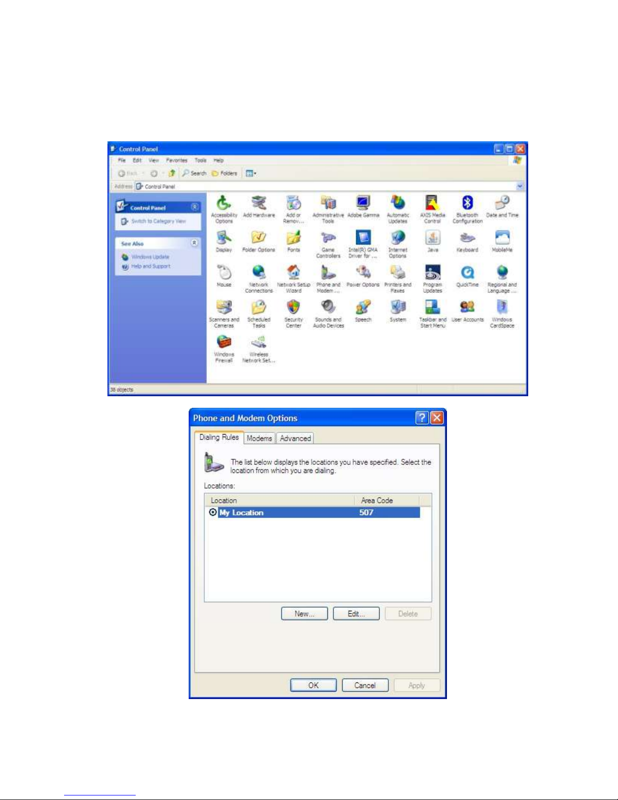
AAPPPPEENNDDIIXX AA –– CCRREEAATTIINNGG AA DDIIAALL--UUPP NNEETTWWOORRKKIINNGG CCOONNNNEECCTTIIOONN
Windows XP
Add Standard Windows Modem
001-0004-819 Rev01
Page 50 of 62
Page 51

001-0004-819 Rev01
Page 51 of 62
Page 52

001-0004-819 Rev01
Page 52 of 62
Page 53

Page 53 of 62
001-0004-819 Rev01
Page 54

Configuring the Modem
001-0004-819 Rev01
Page 54 of 62
Page 55

Create a Dial-Up Networking (DUN) Connection
001-0004-819 Rev01
Page 55 of 62
Page 56

001-0004-819 Rev01
Page 56 of 62
Page 57

001-0004-819 Rev01
Page 57 of 62
Page 58

001-0004-819 Rev01
Page 58 of 62
Page 59
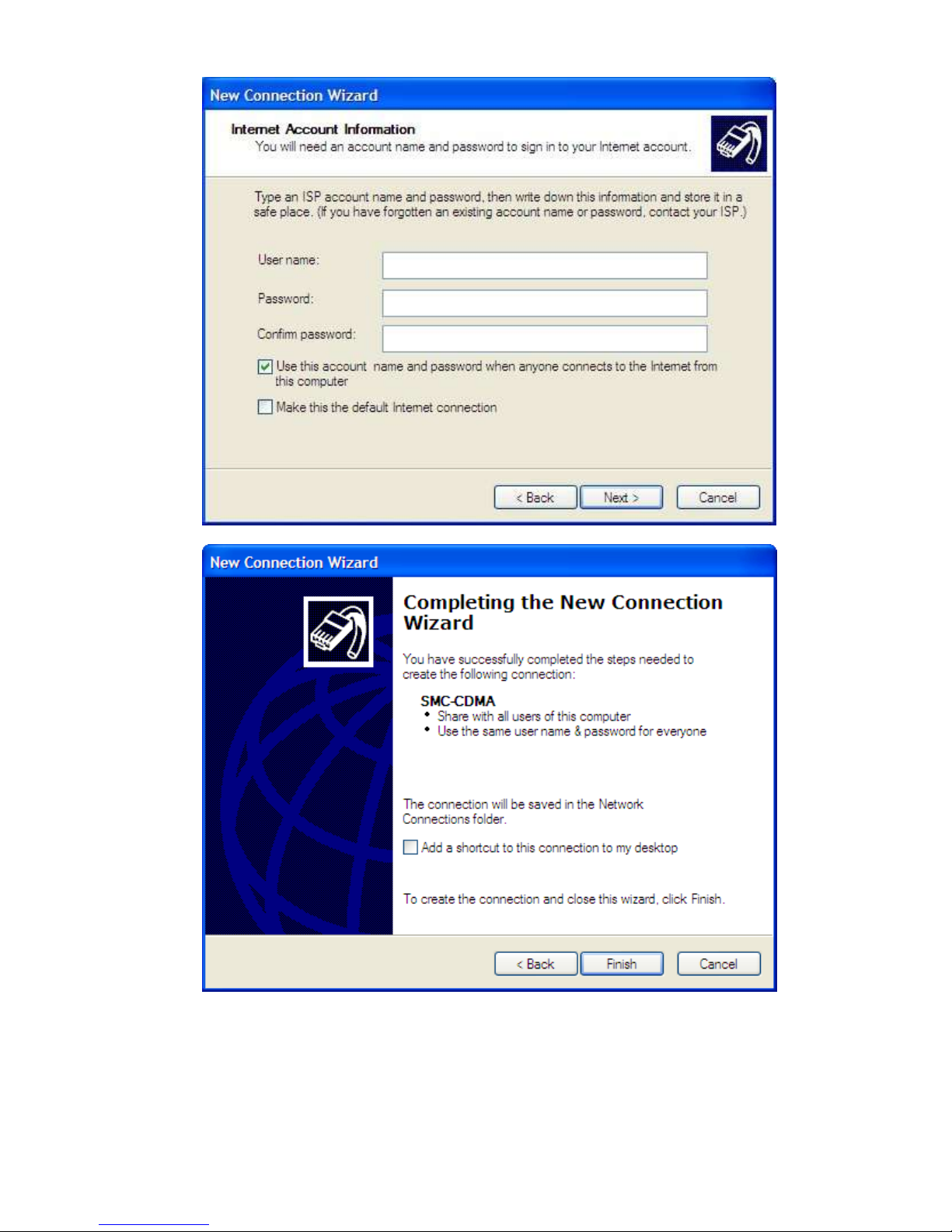
001-0004-819 Rev01
Page 59 of 62
Page 60

001-0004-819 Rev01
Page 60 of 62
Page 61

001-0004-819 Rev01
Page 61 of 62
Page 62

AAPPPPEENNDDIIXX BB –– WWAARRRRAANNTTYY SSTTAATTEEMMEENNTT
CalAmp warrants to the original purchaser for use ("Buyer") that data telemetry products
manufactured by DRL ("Products") are free from defects in material and workmanship and will
conform to DRL's published technical specifications for a period of, except as noted below, one (1)
year from the date of shipment to Buyer. DRL makes no warranty with respect to any equipment not
manufactured by DRL, and any such equipment shall carry the original equipment manufacturer's
warranty only. DRL further makes no warranty as to and specifically disclaims liability for,
availability, range, coverage, grade of service or operation of the repeater system provided by the
carrier or repeater operator. Any return shipping charges for third party equipment to their
respective repair facilities are chargeable and will be passed on to the Buyer.
If any Product fails to meet the warranty set forth above during the applicable warranty period and
is returned to a location designated by DRL. DRL, at its option, shall either repair or replace such
defective Product, directly or through an authorized service agent, within thirty (30) days of receipt
of same. No Products may be returned without prior authorization from DRL. Any repaired or
replaced Products shall be warranted for the remainder of the original warranty period. Buyer shall
pay all shipping charges, handling charges, fees and duties for returning defective Products to DRL
or DRL's authorized service agent. DRL will pay the return shipping charges if the Product is repaired
or replaced under warranty, exclusive of fees and duties. Repair or replacement of defective
Products as set forth in this paragraph fulfills any and all warranty obligations on the part of DRL.
This warranty is void and DRL shall not be obligated to replace or repair any Products if (i) the
Product has been used in other than its normal and customary manner; (ii) the Product has been
subject to misuse, accident, neglect or damage or has been used other than with DRL approved
accessories and equipment; (iii) unauthorized alteration or repairs have been made or unapproved
parts have been used in or with the Product; or (iv) Buyer failed to notify DRL or DRL's authorized
service agent of the defect during the applicable warranty period. DRL is the final arbiter of such
claims.
THE AFORESAID WARRANTIES ARE IN LIEU OF ALL OTHER WARRANTIES, EXPRESSED AND
IMPLIED, INCLUDING BUT NOT LIMITED TO, ANY IMPLIED WARRANTY OF MERCHANTABILITY OR
FITNESS FOR A PARTICULAR PURPOSE. DRL AND BUYER AGREE THAT BUYER'S EXCLUSIVE REMEDY
FOR ANY BREACH OF ANY OF SAID WARRANTIES IT AS SET FORTH ABOVE. BUYER AGREES THAT IN
NO EVENT SHALL DRL BE LIABLE FOR INCIDENTAL, CONSEQUENTIAL, SPECIAL, INDIRECT OR
EXEMPLARY DAMAGES WHETHER ON THE BASIS OF NEGLIGENCE, STRICT LIABILITY OR
OTHERWISE. The purpose of the exclusive remedies set forth above shall be to provide Buyer with
repair or replacement of non-complying Products in the manner provided above. These exclusive
remedies shall not be deemed to have failed of their essential purpose so long as DRL is willing and
able to repair or replace non-complying Products in the manner set forth above.
This warranty applies to all Products sold worldwide. Some states do not allow limitations on implied
warranties so the above limitations may not be applicable. You may also have other rights, which
vary from state to state.
EXCEPTIONS
ONE YEAR: Labor to replace defective parts in repeaters or base stations
THIRTY DAY: Tuning and adjustment of telemetry radios
NO WARRANTY: Fuses, lamps and other expendable parts
Effective 1/2008
Page 62 of 62
001-0004-819 Rev01
 Loading...