

Page 1
TM
LMU-26xx
Install Guide
CalAmp Corp.
13645 Dulles Technology Drive, Herndon, VA 20171 Document: MBUD-0199v3.3
Phone: 703. 262.0500 November 2014
Fax: 703.262.0380
www.calamp.com
Page 2

CalAmp | LMU-26xx Install Guide
Revision History:
Version #
Revision Date
Author
Details
1.0
3/2/2011
Marketing
Baseline release
1.1
5/7/2011
Marketing
Unit information revised
1.2
3/27/2012
Product
Instruction for install in weather exposed
environments
2.0
4/24/2013
ABP
Revised style and device name.
3.0
1/30/2014
ABP
Added Buzzer, LED, jPOD and vPOD instructions.
3.1
2/10/14
ABP
Updated P/N for standard wiring harness
3.2
8/11/2014
Allen Frederick
Added sections 3.1 & 3.2 showing various wiring
harness and accessories. Updated installation
instructions for JPOD and VPOD. Added instructions
for new JPOD/VPOD wiring harness 5C261.
3.3
11/4/2014
Product
Revised and updated jPOD and vPOD
Added Privacy switch wiring
CalAmp | LMU-26xxTM Install Guide
Copyright © 2013 CalAmp Corporation. All rights reserved.
Printed in the United States of America.
All trademarks used are properties of their respective owners.
Products offered may contain software proprietary to CalAmp or other parties. The offer of supply
of these products and services does not include or infer any transfer of ownership. No part of the
documentation or information supplied may be divulged to any third party without the express
written consent of CalAmp.
CalAmp reserves the right to modify the equipment, its specification or this manual without prior
notice, in the interest of improving performance, reliability, or servicing. At the time of publication
all data is correct for the operation of the equipment at the voltage and/or temperature referenced.
Performance data indicates typical values related to the
particular product.
Product updates may result in differences between the information provided in this manual and the
product shipped. We have made every effort to ensure the accuracy of all information contained in
this document; however, CalAmp makes no expressed or implied warranty or representation based
upon the enclosed information.
Page ii MBUD-0199v3.3
Page 3

CalAmp | LMU-26xx Install Guide
TABLE OF CONTENTS
1 REGULATORY INFORMATION ..................................................................................... 1
1.1 HUMAN EXPOSURE COMPLIANCE STATEMENT .................................................................................. 1
1.2 HARDWARE PRECAUTIONS ............................................................................................................. 1
2 INTRODUCTION .......................................................................................................... 2
2.1 GUIDE PREREQUISITES .................................................................................................................. 2
3 LMU-26XX OVERVIEW ................................................................................................ 3
3.1 AVAILABLE WIRING HARNESS ......................................................................................................... 4
3.2 ACCESSORIES ............................................................................................................................... 5
3.3 ENVIRONMENTAL SPECIFICATIONS .................................................................................................. 6
4 PRE-INSTALLATION CONSIDERATIONS ........................................................................ 7
4.1 PLAN THE INSTALLATION ............................................................................................................... 7
4.2 SIZE AND PLACEMENT OF LMU-26XX .............................................................................................. 7
4.3 PROTECTION FROM HEAT .............................................................................................................. 8
4.4 VISIBILITY OF DIAGNOSTIC LEDS ..................................................................................................... 8
4.5 CABLE LENGTH ............................................................................................................................ 8
4.6 MOISTURE AND WEATHER PROTECTION .......................................................................................... 9
4.7 PREVENTING ACCIDENTAL OR UNAUTHORIZED MODIFICATION ............................................................ 9
5 LMU-26XX INSTALLATION ......................................................................................... 10
5.1 SELECT THE LOCATION FOR THE LMU-26XX AND INSTALL IT ............................................................. 11
5.1.1 Under Dash Installation .................................................................................................. 12
5.1.2 Installation in exposed area ........................................................................................... 15
5.2 INSTALL POWER CONNECTIONS ............................................................................................ 15
5.2.1 Secure All Cables ............................................................................................................ 20
5.3 OPTIONAL BUZZER ASSEMBLY CABLE ............................................................................................. 21
5.4 OPTIONAL SWITCH WITH LED CABLE WITH BUZZER .......................................................................... 22
5.5 CONNECT OPTIONAL INPUTS ................................................................................................. 23
5.6 INSTALL OPTIONAL SERIAL CABLES ........................................................................................ 24
MBUD-0199v3.3 Page iii
Page 4

CalAmp | LMU-26xx Install Guide
5.6.1 Serial/Host/AUX 1 .......................................................................................................... 25
5.6.2 Serial/AUX 2 – Garmin Serial Cable ................................................................................ 26
5.6.3 Serial/AUX2 – jPOD Adapter and jPOD Cable ................................................................ 27
5.6.4 Serial/AUX 2 – vPOD Adapter ......................................................................................... 30
5.6.5 Privacy Switch................................................................................................................. 33
5.6.6 Secure All Cables ............................................................................................................ 34
5.7 VERIFY LMU-26XX OPERATIONS .................................................................................................. 35
5.7.2 STATUS LEDS .................................................................................................................. 35
5.7.3 COMM Verification ........................................................................................................ 36
5.7.4 GPS Verification .............................................................................................................. 36
5.7.5 Inbound Verification ...................................................................................................... 36
5.8 GUIDELINES FOR TROUBLESHOOTING COMMON PROBLEMS .............................................................. 37
6 DE-INSTALLATION INSTRUCTIONS ............................................................................. 38
7 WARRANTY .............................................................................................................. 39
APPENDIX A – LMU-26XX ACCESSORY CABLES AND PIGTAIL WIRING INSTRUCTIONS ....... 40
PRIMARY CONNECTOR ........................................................................................................................... 40
LMU-26XX – FULL I/0 WIRING HARNESS – P/N 5C908 ............................................................................ 42
LMU-26XX - SERIAL ADAPTER ................................................................................................................ 43
7.1 BUZZER AND CABLE ASSEMBLY – P/N 4C765 ................................................................................ 44
7.2 GARMIN TO 5-PIN SERIAL CABLE – P/N 133688 ............................................................................ 44
7.3 JPOD ADAPTER – P/N 134152-JPOD ......................................................................................... 45
7.4 VPOD 5-PIN SERIAL OBD-II ADAPTER – P/N 133917 ................................................................... 45
8 CUSTOMER SUPPORT CONTACT INFORMATION ........................................................ 46
Page iv MBUD-0199v3.3
Page 5

CalAmp | LMU-26xx Install Guide
LIST OF FIGURES
Figure 1: CalAmp LMU-26xx Device ....................................................................................................... 3
Figure 2: P/N 5C260 No jPOD/vPOD Accessories .................................................................................. 4
Figure 3: P/N 5C908 No jPOD/vPOD Accessories .................................................................................. 4
Figure 4: P/N 5C261 jPOD or vPOD ........................................................................................................ 4
Figure 5: Coil Excess Cable ..................................................................................................................... 8
Figure 6: Tamper Resistant Materials .................................................................................................... 9
Figure 7: LMU-26xx Under Dash Mount .............................................................................................. 12
Figure 8: Re-closable Fastener Tape on LMU-26xx .............................................................................. 13
Figure 9: Re-closable Fastener Tape - Prior to Mounting .................................................................... 13
Figure 10: LMU-26xx Standard Wiring Harness (P/N: 5C908) ............................................................. 15
Figure 11: Power Leads ........................................................................................................................ 16
Figure 12: Ring Connector on Ground Wire ......................................................................................... 17
Figure 13: Ground Connection ............................................................................................................. 17
Figure 14: Main Vehicle Wire Harness ................................................................................................. 18
Figure 15: Ignition Wires ...................................................................................................................... 18
Figure 16: Wrapped Fuse Lead ............................................................................................................ 19
Figure 17: Applied Torque Seal ............................................................................................................ 19
Figure 18: Secured Cables .................................................................................................................... 20
Figure 19: Connect Buzzer Assembly to the LMU-26xx Power Accessory Cable 5C260 or 5C261 ...... 21
Figure 20: LMU-26xx Buzzer Assembly Connected .............................................................................. 21
Figure 21: Connect Switch with LED cable to LMU-26xx Power Accessory Cable ............................... 22
Figure 22: LMU-26xx Switch/LED Assembly Connected ...................................................................... 22
Figure 23: LMU-26xx Connectors ......................................................................................................... 23
Figure 24: LMU-26xx Standard Wiring Harness and Connectors ......................................................... 24
Figure 25: LMU-26xx DB9 Serial Connection ....................................................................................... 25
Figure 26: LMU-26xx DB9 Serial Connection ....................................................................................... 25
Figure 27: LMU-26xx and Garmin PND Cable Connection ................................................................... 26
Figure 28: jPOD Adapter (PN: 134152) Figure 29: jPOD Cable (PN: 5C909-2) .............................. 27
Figure 30: 6-pin j1708 Cable. (PN: 8973002002) Figure 31: 9 PIN JBUS J1936 TO 6 PIN J1708
ADAPTER CABLE (PN:8973002001) ............................................................................................... 27
Figure 32: AUX2 Connection ................................................................................................................ 28
Figure 33: Connect jPOD Cable and jPOD Adapter Using Serial Connector......................................... 29
Figure 34: LMU-26xx and jPOD Assembly ............................................................................................ 29
Figure 35: vPOD Adapter (133917-VPOD) ........................................................................................... 30
Figure 36: AUX2 Connection ................................................................................................................ 31
Figure 37: vPOD With Harness 5C261 Figure 38: vPOD With Harness 5C260 or 5C908 .................. 32
Figure 39: vPOD Adapter and Vehicle OBD-II Port ............................................................................... 32
Figure 40 - DPST switch diagram .......................................................................................................... 33
Figure 41 – Example illuminated rocker switch ................................................................................... 33
MBUD-0199v3.3 Page v
Page 6

CalAmp | LMU-26xx Install Guide
Figure 42 - Setup in Device Admin ....................................................................................................... 33
Figure 43: Location of Status LEDs ....................................................................................................... 36
Figure 44: FleetOutlook Reporting Verification ................................................................................... 36
Figure 45: LMU-26xx Connectors ......................................................................................................... 41
Figure 46: Full I/O Wiring Harness ....................................................................................................... 42
Figure 47: LMU-26xx Serial Pigtail Adapter ......................................................................................... 43
Figure 48: LMU-26xx DB9 Serial Cable ................................................................................................. 43
Figure 49: Buzzer and Cable Assembly ................................................................................................ 44
Figure 50: Garmin to 5-Pin Serial Cable ............................................................................................... 44
Figure 51: jPOD Adapter ...................................................................................................................... 45
Figure 52: vPOD 5-Pin Serial OBD-II Adapter ....................................................................................... 45
Page vi MBUD-0199v3.3
Page 7

CalAmp | LMU-26xx Install Guide
1 REGULATORY INFORMATION
1.1 HUMAN EXPOSURE COMPLIANCE STATEMENT
Pursuant to 47 CFR § 24.52 of the FCC Rules and Regulations, personal communications services (PCS)
equipment is subject to the radio frequency radiation exposure requirements specified in § 1.1307(b), §
2.1091 and § 2.1093, as appropriate.
CalAmp certifies that it has determined that the LMU-26xx complies with the RF hazard requirements
applicable to broadband PCS equipment operating under the authority of 47 CFR Part 24, Subpart E of
the FCC Rules and Regulations. This determination is dependent upon installation, operation and use of
the equipment in accordance with all instructions provided.
The LMU-26xx is designed for and intended to be used in fixed and mobile applications. “Fixed” means
that the device is physically secured at one location and is not able to be easily moved to another
location. “Mobile” means that the device is designed to be used in other than fixed locations and
generally in such a way that a separation distance of at least 20 cm is normally maintained between the
transmitter’s antenna and the body of the user or nearby persons. The LMU-26xx is not designed for or
intended to be used in portable applications (within 20 cm of the body of the user) and such uses are
strictly prohibited.
To ensure that the LMU-26xx complies with current FCC regulations limiting both maximum RF output
power and human exposure to radio frequency radiation, a separation distance of at least 20 cm must
be maintained between the unit’s antenna and the body of the user and any nearby persons at all times
and in all applications and uses. Additionally, in mobile applications, maximum antenna gain must not
exceed 3 dBi.
1.2 HARDWARE PRECAUTIONS
Electrical Over-Stress (EOS)
The LMU-26xx GPS receiver can be damaged if exposed to an RF level that exceeds its maximum input
rating. Such exposure can happen if a nearby source transmits an RF signal at sufficiently high level to
cause damage.
Storage and Shipping
One potential source of EOS is proximity of one LMU-26xx GPS Antenna to another LMU-26xx GSM
Antenna. Should one of the units be in a transmit mode, the potential exists for the other unit to
become damaged. Therefore, any LMU-26xx should be kept at least four inches apart from any active
LMU-26xx or any other active high power RF transmitter with power greater than 1 Watt.
MBUD-0199v3.3 Page 1
Page 8

CalAmp | LMU-26xx Install Guide
2 INTRODUCTION
The LMU-26xx Install Guide provides important electrical safety and radio-frequency compliance
information, environmental specifications and installation procedures for the CalAmp LMU-26xx and
optional serial cables.
2.1 GUIDE PREREQUISITES
In order to limit the size and scope of this guide, the following assumptions have been made about the
user:
Working knowledge of GPS concepts and terminology.
Experience with installing equipment in vehicles.
Page 2 MBUD-0199v3.3
Page 9
CalAmp | LMU-26xx Install Guide
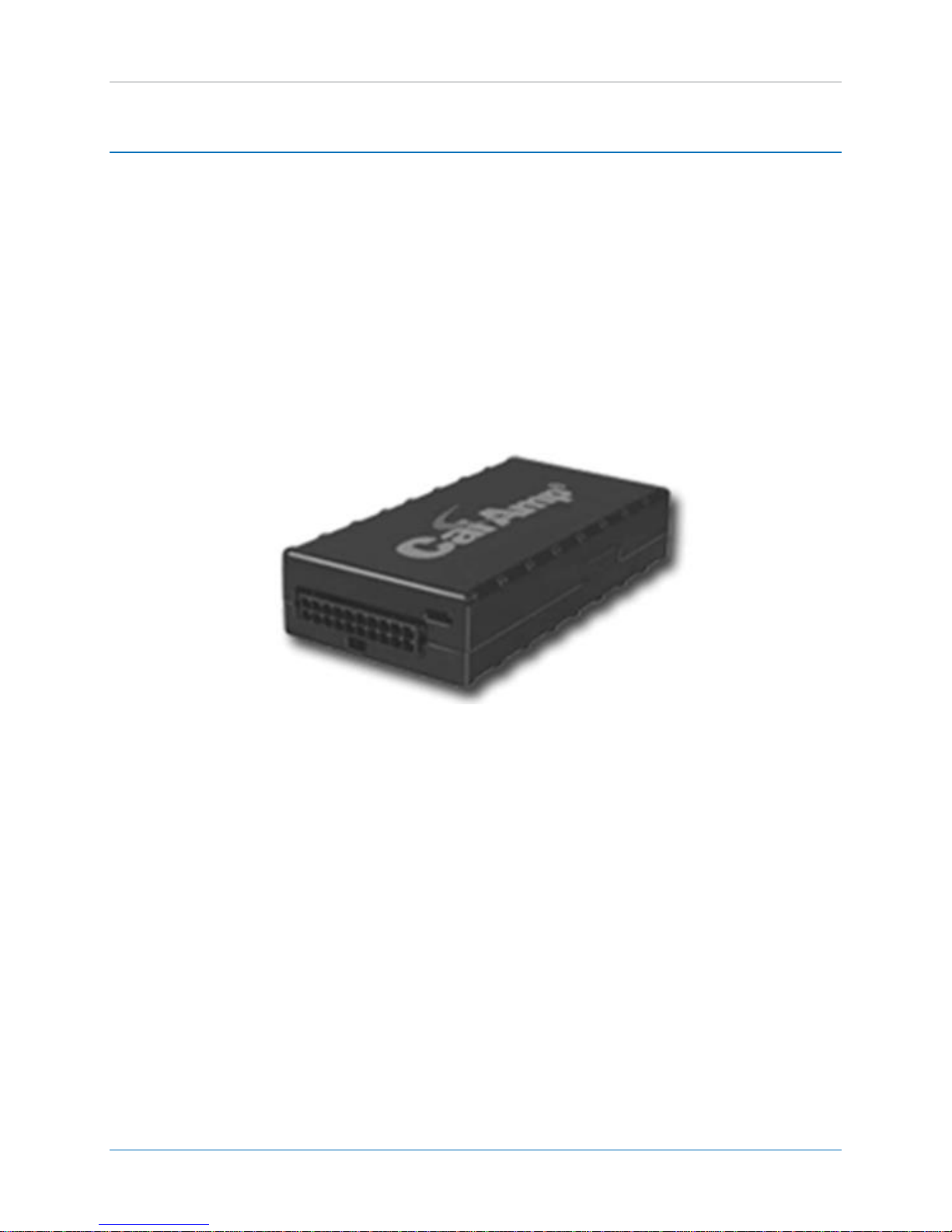
3 LMU-26XX OVERVIEW
The CalAmp LMU-26xx is an integrated Cellular/GPS communications device for use in-vehicle tracking.
It provides communications for vehicle position and operating information as part of an overall vehicle
tracking solution. It is installed within the vehicle in order to provide this information, and is wired into
and powered by the vehicle’s power supply.
The device features integrated cellular and GPS antennas in order to provide the vehicle with a compact
and full-function platform for capturing vehicle position and operational information and transmitting it
for use by dispatchers and other back-office personnel.
Figure 1: CalAmp LMU-26xx Device
MBUD-0199v3.3 Page 3
Page 10
CalAmp | LMU-26xx Install Guide
Wire Harness
P/N
Description
No JPOD or VPOD
JPOD or VPOD
Buzzer
Switch/LED
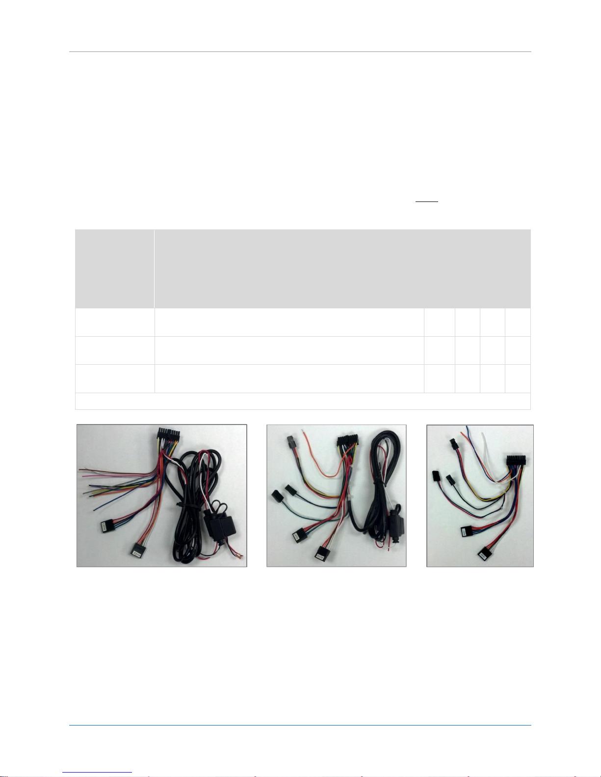
5C908
Power Harness (No JPOD or VPOD, No Connectors For
Accessories)
X 5C260
Power Harness (No JPOD or VPOD, with/without Buzzer and/or
Switch LED)
X
X* X X
5C261
Power Harness (JPOD or VPOD, with/without Buzzer and/or
Switch LED)
X* X X
* For Installations using jPOD or vPOD, the 5C261 optional cable is recommended for an easier install.
No jPOD/vPOD Accessories
Figure 4: P/N 5C261
jPOD or vPOD
3.1 AVAILABLE WIRING HARNESS
The LMU-26XX ships with the 5C908 wiring harness. This harness requires hard wiring of the power,
ground and ignition wire.
The 5C260 is an optional cable with multiple connectors for standard I/O devices, such as buzzer, light
and driver ID sensor. This enables hard wiring of the power, ground and ignition wire except when using
a vPOD or jPOD. Both vPOD and jPOD provide power to the device without the need for hard wiring.
See installation instructions for proper wiring.
The 5C261 is an optional cable with same connectors as the 5C260; however, it is a short harness and
provides power, ground and ignition from the vehicle’s Jbus or OBD port. This must be used with either
the vPOD or jPOD to work properly.
Figure 3: P/N 5C908
No jPOD/vPOD Accessories
Figure 2: P/N 5C260
Page 4 MBUD-0199v3.3
Page 11

CalAmp | LMU-26xx Install Guide
Accessories
Description
4C764
CABLE ASSY, SWITCH/LED
4C765
CABLE ASSY, BUZZER
133337-5
DB9 Serial Cable (typically used on Aux1 serial port)
133688
Garmin Serial Cable (Aux2 serial port)
133917-VPOD
ACCESSORY, VPOD (Aux2 serial port)
134152-JPOD
ACCESSORY, JPOD (Aux2 serial port)
5C909-2
jPOD Y Cable (connects D9 pin DIN connector on vehicle to the jPOD 9 pin port)
8973002002
6-pin j1708 Y Cable (substitute for the 6C909-2 cable in older vehicles)
8973002001
9 PIN JBUS J1936 TO 6 PIN J1708 ADAPTER CABLE (Converts a 6 pin J1708
connector vehicle to 9 pin ready for use with 5C909-2 cable.
3.2 ACCESSORIES
MBUD-0199v3.3 Page 5
Page 12

CalAmp | LMU-26xx Install Guide
Size
4.0" long x 2.0" wide x 0.85" high
10.2 cm long x 5.1 cm wide x 2.2 cm high
Weight
2.61 ounces / 75g (external antenna)
3.0 ounces / 85g (internal antenna)
Operating Temperature
-30o C to 75o C
Storage Temperature
-40o C to 85o C
Humidity
0% to 95% relative humidity, non-condensing
Shock and Vibration
SAE Test: SAE J1455 Compliant
Mil Standard 202G and 810F Compliant
Ground vehicle environment with associated shock and vibration
Electromagnetic Compatibility
(EMC/EMI)
SAE Test: SAE J1113 Parts 2, 12, 21 and 41 Compliant
FCC Part 15B Compliant
Industry Canada Compliant
EMC compliant for a ground vehicle environment
Operating Voltage Range
6 – 32VDC
Power Consumption
Active Standby :70mA at 12VDC
Sleep on Network (SMS): 10mA
Sleep on Network (GPRS): 20mA
Deep Sleep: 3mA
GPS 50 channel (with SBAS, DGPS) GPS Receiver
2m CEP (with SA off)
-160 dBm tracking sensitivity
Communications (Comm)
Quad Band Class 12 GPRS Modem
850 MHz (Class 4) – 2W
900 MHz (Class 4) – 2W
1800 MHz (Class 1) – 1W
1900 MHz (Class 1) -1 W
GPRS Packet Data (UDP)
SMS
RoHS Compliant
3.3 ENVIRONMENTAL SPECIFICATIONS
The LMU-26xx is designed to operate in environments typically encountered by fleet vehicles, including
wide temperature extremes, voltage transients and potential interference from other vehicle
equipment.
To ensure proper operation in such an environment, the LMU-26xx was subjected to standard tests
defined by the Society of Automotive Engineers (SAE). The specific tests included temperature, shock,
vibration and EMI/EMC. These tests were performed by independent labs and documented in a detailed
test report. In accordance with Appendix A of SAE J1113 Part 1, the Unit is considered a “Functional
Status Class B, Performance Region II” system that requires Threat Level 3 Testing.
The following shows the environmental conditions the LMU-26xx is designed to operate in and the
relevant SAE tests that were performed. No formal altitude tests were conducted.
Page 6 MBUD-0199v3.3
Page 13

CalAmp | LMU-26xx Install Guide
4 PRE-INSTALLATION CONSIDERATIONS
The installation of the LMU-26xx and its antennas can have a major impact on device performance. It is
recommended that installers be familiar with the installation of GPS and cellular devices and are
comfortable in a vehicle environment.
4.1 PLAN THE INSTALLATION
Verify Power, Ground and Ignition. Be sure to check each source (power, ground and ignition) to ensure
that the proper signaling exists. This is typically accomplished with a multi-meter.
Before drilling any holes or running any wires, decide where each hardware component will be installed
(LMU-26xx, antennas, peripherals, etc.). Verify that all cables running to the LMU-26xx will not be bent
or constricted. Verify that the LMU-26xx install location is free from direct exposure to the elements
(e.g., sun, heat, rain, moisture etc.).
Be advised that an installation that violates the environmental specifications of the LMU-26xx will void
the warranty.
The best way to ensure a trouble-free installation is to consider your options and make appropriate
decisions before you start. Review the vehicle and determine the best install approach for the LMU-26xx
for the following purposes:
Accurate data gathering and simulation of how customers actually use your solution.
Ongoing monitoring and maintenance of LMU-26xx equipment
Accidental or intentional alteration of the equipment or cable connections.
4.2 SIZE AND PLACEMENT OF LMU-26XX
When planning device installation in a vehicle, take in account the dimensions of the LMU-26xx before
actual installation. Typical installations place the LMU-26xx under the vehicle dashboard, or in the A
Pillar. Verify that you can access to the device, as under some circumstances it may be necessary to add
additional wiring or connections to the LMU-26xx.
Refer to Section 3.3: Environmental Specifications for the exact measurements and specifications of the
LMU-26xx.
Verify the LMU-26xx will fit before drilling any holes or running cable.
Ensure that all cables running to the LMU-26xx will not be bent or constricted. Damage to the cables
may impede the LMU-26xx’s performance.
Verify that the installation point will not violate any of the LMU-26xx’s environmental specification.
Improper installation of the LMU-26xx may void the warranty.
MBUD-0199v3.3 Page 7
Page 14

CalAmp | LMU-26xx Install Guide
4.3 PROTECTION FROM HEAT
We recommend that you do not place the LMU-26xx in an unusually warm location such as directly near
heater vents, hot engine components or in direct sunlight.
Refer to Section3.3: Environmental Specifications for the maximum temperature tolerated by the
LMU-26xx.
4.4 VISIBILITY OF DIAGNOSTIC LEDS
Status LED lights on the front of the LMU-26xx provide valuable information about the operation of the
device. When feasible, attempt to install the LMU-26xx in such a way that the lights are visible with
reasonable ease.
You may find it useful to be able to view the LEDs periodically to make sure that the LMU-26xx is
operating properly. If you encounter a problem or poor performance with the LMU-26xx, you may need
to read the LEDs to troubleshoot the issue. If you cannot resolve the issue, you will need to provide the
LED information to the CalAmp Customer Support Team.
Refer to Section 5.7.2: Status LEDs for information on how to interpret the lights.
4.5 CABLE LENGTH
The harness cables, which are provided for connecting to the LMU-26xx to the vehicle or other auxiliary
device, should be used at the length provided. Do not cut cables. Instead, coil any excess cable length,
making sure not to crimp or flatten the cables.
Figure 5: Coil Excess Cable
Page 8 MBUD-0199v3.3
Page 15

CalAmp | LMU-26xx Install Guide
Figure 6: Tamper Resistant Materials
4.6 MOISTURE AND WEATHER PROTECTION
The LMU-26xx is not a weatherproof device and must be kept dry. The mounting location should be
inside the passenger compartment of the vehicle safe from physical damage and where it is not exposed
to moisture or water. In a typical inside-vehicle installation, this is not a common concern; however,
avoid installing the device below the vehicle’s cup holders, or where rain might easily splash into the
compartment when a door is opened.
If the LMU-26xx is installed in a vehicle with a cab exposed to the weather, additional protection is
required to avoid damage to the device, which could void the warranty. There are numerous
alternatives for protecting the device. One of the best options is to use an Otterbox 2000. You can
purchase from Amazon.com or directly from Otterbox:
http://www.otterbox.com/OtterBox-2000-Clear/OTR3-2000S-01,default,pd.html?dwvar_OTR3-2000S01_color=01&start=3&cgid=otterbox-2000-cases.
Note: For environmentally challenging conditions, consider utilizing the CalAmp TTU-2820.
4.7 PREVENTING ACCIDENTAL OR UNAUTHORIZED MODIFICATION
If you anticipate that fleet drivers or others might tamper with the devices once installed, take steps to
ensure that it is not easy to disconnect the wiring or remove the device from its power source. A tamper
resistant installation couples a zip-tie secured around the device with a tamper seal applied to protect
against potential interference and to deter intentional tampering. When the tamper seal is removed, the
seal self-destructs to indicate removal and leaves behind a dot-pattern residue on the device.
MBUD-0199v3.3 Page 9
Page 16

CalAmp | LMU-26xx Install Guide
5 LMU-26XX INSTALLATION
Installing the LMU-26xx is not difficult, but you must consider the variables involved, such as the vehicle
type and location of existing equipment. Installation time can vary depending upon the installer’s
experience and the vehicle design. The average time for installation is approximately 45 minutes. A
single individual can perform most installation operations. CalAmp offers an installation training
program or can supply a list of recommended installation vendors in your area.
Prior to beginning the installation, verify that you have the parts and tools necessary to complete the
installation. Additionally, read entire installation procedure before beginning. Some of the procedures
require a choice between several installation options.
To install the LMU-26xx:
1. Select location for mounting the device and install it.
For ease of installation, the LMU-26xx has internal GPS and Cellular antennas. Assess cable routes
while considering placement.
2. Install the power, ignition, and ground connections.
3. Install optional buzzer and/or LED button.
4. Install optional I/O connections.
5. Install optional serial cables.
6. Secure all cables to rigid mounts with cable restraints.
7. Verify operation of the LMU-26xx.
Page 10 MBUD-0199v3.3
Page 17

CalAmp | LMU-26xx Install Guide
5.1 SELECT THE LOCATION FOR THE LMU-26XX AND INSTALL IT
Determine the desired mounting location. The most common locations are under the dash or on the
front windshield. We recommend under the dash.
For an exposed location, refer to Section 5.1.2: Installation in an Exposed Area.
When determining mounting location, the primary consideration is GPS satellite visibility by the device.
The required installation orientation of the LMU-26xx is label side up. The label should face the sky or
toward windshield.
Note: When performing installation tasks requiring the operation of power, follow recommended safety
procedures, including use of safety eye-wear. In addition, avoid drilling through wires, mounted fixtures
or equipment.
MBUD-0199v3.3 Page 11
Page 18

CalAmp | LMU-26xx Install Guide
5.1.1 UNDER DASH INSTALLATION
If the LMU-260 is mounted under the dashboard of the vehicle (Figure 6), ensure the device is mounted
with the “label side” facing up. Do not install the device where it will be obstructed by metal
components. Common install locations are in the void above the glove box (if no airbag present) or
above the vents.
You may need to remove part of the dash facing for access. Typically, the dash facing is attached with
just clips. Do not use excessive force wedging the device into a location under the dash. Use the
provided ‘re-closable fastener tape’ to attach the device to the underside of the dash as described in the
steps below.
Page 12 MBUD-0199v3.3
Figure 7: LMU-26xx Under Dash Mount
Page 19

CalAmp | LMU-26xx Install Guide
1. Under dash mounting may or may not require the use of the re-closable fastener tape. If the
tape is required, follow instructions below:
Clean and prepare the mounting surface and the device before attaching the provided
re-closable fastener tape.
One at a time, remove the backing from two pieces of the re-closable fastener tape.
Firmly press on the sticky-side of the re-closable fastener tape onto the device on both
sides of the device, front or back of device depending on installation requirements
(Figure 7).
Figure 8: Re-closable Fastener Tape on LMU-26xx
Press the other pieces of re-closable fastener tape, bumpy sides together, onto the
device. Do not remove backing (Figure 8).
Figure 9: Re-closable Fastener Tape - Prior to Mounting
2. Depending on install location, you may need to attach the wiring harnessed to the device prior
to installation. After the wiring harness is inserted into the device, gently pull on the connector
to ensure the harness is locked in place.
3. Remove the backing from the re-closable fastener tape.
4. Firmly press the device with the re-closable fastener tape onto the mounting surface in the
previously selected and cleaned location, wait several seconds before releasing pressure.
MBUD-0199v3.3 Page 13
Page 20

CalAmp | LMU-26xx Install Guide
5. Route the power cable to the source of 12 Volts continuous and 12 Volts ignition switched.
Refer to Section 5.2: Install Power Connections for detailed instructions on installing the
power cable.
6. Carefully remove any panels required for access as needed. Ensure there are no sharp edges
that may abrade the wire. Use a suitable means to protect the cable from the sharp edge to
eliminate possible wear or reroute the wire if possible.
7. If applicable, connect Buzzer and/or Switch with LED Cables.
Refer to Section 5.3: Optional Buzzer Assembly Cable instructions and/or Section 5.4:
Optional Switch with LED Cable instructions.
8. If applicable, route the I/O Cable to the source of the I/O signals.
Refer to Section 5.5: Connect Optional Inputs for detailed instructions on installing the I/O
Cable.
9. If applicable, connect the optional serial cables (e.g., NMEA or Garmin).
Refer to Section 5.6: Install Optional Serial Cables for detailed instructions on install the
serial cables.
10. Follow the steps outlined in Section 5.5: Verify LMU-26xx Operations to verify successful
installation.
Page 14 MBUD-0199v3.3
Page 21

CalAmp | LMU-26xx Install Guide
5.1.2 INSTALLATION IN EXPOSED AREA
If the LMU-26xx is installed in a vehicle with an open cab exposed to the weather, a NEMA rated
enclosure suitable for the application must be used to seal out moisture. A recommended alternative is
a TTU-2820 sealed device available from CalAmp.
5.2 INSTALL POWER CONNECTIONS
The LMU-26xx requires a continuous 12 Volts and an ignition switched 12 Volt signal to operate
correctly.
For Harness 5C908 and 5C260, the LMU-26xx power leads with in line fuses are supplied as part of the
wiring harness.
For harness 5C261, the power and ground are an integral part of the harness, but must be installed with
the vPOD or jPOD.
Figure 10: LMU-26xx Standard Wiring Harness (P/N: 5C908)
MBUD-0199v3.3 Page 15
Page 22

CalAmp | LMU-26xx Install Guide
Ignition (White)
+12V (Red)
Ground (Black)
If hard wiring the device, the LMU-26xx power cable has 3 wires: 12 Volts continuous, 12 Volts ignition
switched, and ground.
All power connections must be insulated with electrical tape.
Use care to prevent accidentally shorting any connections. Power Connections should meet
aftermarket electronics industry installation practices.
Power connections, both Constant and Ignition, must be fused using the supplied in line 3A
fuses and holders.
All power connections must be made using manufacturer approved methods for adding
accessories to vehicles.
Figure 11: Power Leads
Page 16 MBUD-0199v3.3
Page 23

CalAmp | LMU-26xx Install Guide
The connection method must be applied to all installations:
1. Install a ring connector on the Ground wire (Black) as shown below.
Figure 12: Ring Connector on Ground Wire
2. Select a common grounding point and connect the negative, grounding-wire lead (black lead) to
its ground, the negative battery lead can be used.
The common ground is through the vehicle’s chassis and connected using a Ring Terminal, Star
Washer and a ½-inch self-tapping screw or using a provided vehicle ground under the dash.
Figure 13: Ground Connection
3. Identify the main harness for the vehicle’s key. Use a DVOM (Multimeter) or test light to verify
the constant +12VDC and Ignition sense wires.
Ignition sensor wire refers to a Key controlled power source that has +12VDC in both the Run
and Start positions. Under no circumstance will the "Accessory Position" produce +12VDC on the
Ignition sensor wire.
MBUD-0199v3.3 Page 17
Page 24

CalAmp | LMU-26xx Install Guide
Figure 14: Main Vehicle Wire Harness
4. Remove insulation from the correct factory ignition wires using T-Strippers. Use care to remove
only the insulation. Do not damage any of the strands. Using a pick or multi-meter probe,
separate the strands.
5. Wrap the Fuse Holder Lead.
Strip about 1½” to 2“of insulation from the Fuse Holder lead. Feed the exposed fuse holder
lead through the hole in the factory wire. Pinch the factory wire back together and wrap the
fuse lead around source wire at least 3 times.
Page 18 MBUD-0199v3.3
Figure 15: Ignition Wires
Page 25

CalAmp | LMU-26xx Install Guide
Figure 16: Wrapped Fuse Lead
6. Insulate and secure the power connections:
Using electrical tape insulate the power connection.
To ensure a tamper resistant connection, apply zip-ties over the tape at the connection
point and apply Torque Seal to the zip-ties.
Figure 17: Applied Torque Seal
MBUD-0199v3.3 Page 19
Page 26

CalAmp | LMU-26xx Install Guide
5.2.1 SECURE ALL CABLES
Verify that all cables are secured with proper connections to components. Coil and secure loose or
excess cable and ensure that it is out of the way of normal vehicle operations. Additionally, verify that
cables are not stretched and do not rub on vehicle components, which could cause unexpected wear.
Figure 18: Secured Cables
Page 20 MBUD-0199v3.3
Page 27

CalAmp | LMU-26xx Install Guide
Buzzer
(4C765)
3-Pin
5.3 OPTIONAL BUZZER ASSEMBLY CABLE
The LMU-26xx can be used to provide a connection to an in-cab buzzer to provide driver behavior
feedback for specific conditions, such as hard braking, hard acceleration and exceeding a defined speed
threshold. You must connect the Buzzer Assembly Cable (P/N 4C765) to the LMU-26xx Power Accessory
Cable (P/N 5C260 or 5C261) and mount the buzzer to a metal or plastic surface of the vehicle. This cable
can be used in combination with the Switch with LED Button Cable (P/N 4C764).
Note: To install the Buzzer Assembly Cable with the LMU-26xx, you must order the Power Accessory
Cable P/N 5C260 or 5C261 – See Section 3.1 “Available Wiring Harness”.
To Connect the Buzzer Assembly Cable:
1. Plug in the 3-pin connector on the Buzzer Assembly Cable to the 3-pin connector on the LMU26xx
Power Accessory cable: (P/N:5C260 or 5C261 – See Section 3.1 “Available Wiring Harness”).
Figure 19: Connect Buzzer Assembly to the LMU-26xx Power Accessory Cable 5C260 or 5C261
2. Mount the buzzer using zip-ties to the secured wiring harness or surface of the vehicle.
You reduce the buzzer noise level by applying heavy tape over the buzzer opening or reduce even
further by wrapping the buzzer in high density foam or plastic.
Harness 5C260 Standard Harness 5C261 with vPOD Harness 5C261 with jPOD
Figure 20: LMU-26xx Buzzer Assembly Connected
MBUD-0199v3.3 Page 21
Page 28

CalAmp | LMU-26xx Install Guide
Switch/LED
(4C764)
4-Pin
5.4 OPTIONAL SWITCH WITH LED CABLE WITH BUZZER
The LMU-26xx can be used to provide a connection to an LED light to provide driver behavior feedback
for specific conditions, such as hard braking, hard acceleration and exceeding a defined speed threshold.
You must connect the Switch with LED Cable (P/N 4C764) to the LMU-26xx Power Accessory Cable (P/N
5C260 or 5C261) and mount the LED light on the dashboard. The Switch with LED Button Cable can be
used in combination with the Buzzer Assembly Cable (P/N 4C765).
Note: To install the Switch/LED Cable with the LMU-26xx, you must order the Power Accessory Cable
(P/N 5C260 or 5C261 – See Section 3.1 “Available Wiring Harness”), which is sold separately.
To Install the LED Button Switch:
1. Determine best placement for LED button on dashboard, and then drill a ½” hole in the dashboard.
2. Remove the nut and washer from the cable, and then feed the wire through the hole until the LED
button is seated in place.
3. Feed the washer and nut up the cable and secure to the back of the LED button in place.
Figure 21: Connect Switch with LED cable to LMU-26xx Power Accessory Cable
4. Plug the 4-pin square connector on the Switch with LED Cable in the 4-pin square connector on the
LMU-26xx Power Accessory Cable (5C260 or 5C261).
5. As an option to drilling a hole in the dashboard, you can purchase a mounting bracket to secure the
LED button in place, such as P/N 55205K2 available from www.McMaster.com.
Harness 5C260 Standard Harness 5C261 with VPOD Harness 5C261 with JPOD
Figure 22: LMU-26xx Switch/LED Assembly Connected
Page 22 MBUD-0199v3.3
Page 29

CalAmp | LMU-26xx Install Guide
Standard Wiring Harness (P/N 5C908) Inputs:
Buzzer/LED Wiring Harness Inputs
(P/N 5C260 and 5C261)
Input 1 – Pin 3 (Blue)
Input 1 – Pin 3 (Blue)
Input 2 – Pin 12 (Orange)
Input 2 – Pin 12 (Orange)
Input 3 – Pin 6 (Violet)
Input 4 – Pin 7 (Grey)
5.5 CONNECT OPTIONAL INPUTS
The LMU-26xx wiring harness comes populated with 4-digital input leads. Use these leads to monitor
status changes for a particular auxiliary device. For example, a boom switch or Power Take Off (PTO).
You can extend these leads using a splice butt and the appropriate length 22AWG wire commonly
available at an automotive parts store or Home Depot.
Figure 23: LMU-26xx Connectors
MBUD-0199v3.3 Page 23
Page 30

CalAmp | LMU-26xx Install Guide
Serial AUX2 for
Garmin (PND),
jPOD or vPOD
Serial AUX1 for
NMEA
5.6 INSTALL OPTIONAL SERIAL CABLES
The LMU-26xx Power Accessory Cables have two serial ports: AUX1 and AUX2. Each wiring harness
comes with both ports pinned out to individual 5-pin Molex pigtail connectors.
.
Figure 24: LMU-26xx Standard Wiring Harness and Connectors
IMPORTANT: The wire colors used on the vPOD and jPOD are confusing in this application. The colors
match those of the AUX1 port on the harness, however the devices actually go to AUX2 port.
Page 24 MBUD-0199v3.3
Page 31

CalAmp | LMU-26xx Install Guide
Serial Connection to
Laptop
USB connection to
Laptop
5.6.1 SERIAL/HOST/AUX 1
The Serial AUX1 port provides a standard serial NMEA stream to an in-vehicle computing device, such as
a laptop. This port is identified by the blue and green wires pinned to one of the Molex connectors. In
order for the LMU-26xx to provide NMEA, you must install the CalAmp DB9 Cable (P/N 133337-5). This
cable comes with the correct Molex connector mate.
To Install the DB9 Cable via AUX1 Serial Port:
1. Connect the DB9 Cable to the LMU-26xx AUX1 serial port, and then connect the DB9 serial
connector to an available serial port on the laptop (Figure 25).
Choose the appropriate COM port on the laptop device. If there is no available serial port, use a
serial to USB adapter (Figure 26). These are readily available for purchase either online or in retail
electronic product stores.
2. Secure the DB9 connection by wrapping it with electrical tape. If the LMU-26xx is powered up,
NMEA will begin working without further configuration.
MBUD-0199v3.3 Page 25
Figure 25: LMU-26xx DB9 Serial Connection
Figure 26: LMU-26xx DB9 Serial Connection
Page 32

CalAmp | LMU-26xx Install Guide
Connection to
Garmin PND
5.6.2 SERIAL/AUX 2 – GARMIN SERIAL CABLE
The Serial/AUX2 port can be used to provide a connection to a CalAmp certified Garmin Personal
Navigation Device (PND). You must install the Garmin Serial Cable (P/N 133688) to establish the
connection between the LMU-26xx and the Garmin PND. This cable comes with the correct Molex
connector mate.
To Install the Garmin Cable via AUX2 Serial Port:
1. Connect the Garmin Serial Cable’s 5-pin serial to the LMU-26xx AUX2 serial port.
You can identify the LMU-26xx AUX2 serial port by the white/orange and white/yellow wires pinned
to one of the Molex connectors.
Figure 27: LMU-26xx and Garmin PND Cable Connection
2. Connect the Garmin Serial Cable to the certified Garmin PND.
3. If the LMU-26xx is powered on, communications between the LMU-26xx and the Garmin PND will
begin working without further configuration.
Page 26 MBUD-0199v3.3
Page 33

CalAmp | LMU-26xx Install Guide
5.6.3 SERIAL/AUX2 – jPOD ADAPTER AND jPOD CABLE
The Serial/AUX2 port provides a connection to the vehicle’s diagnostic port to read and report heavy-
duty engine condition and performance data, such as engine temperature and fault codes. You must
install the jPOD Adapter (P/N 134152) and jPOD Cable (5C909-2) to access the vehicle bus data. The
cable typically is made up of a 9-Pin Deutsch connector to a male DE-15 connector.
Figure 28: jPOD Adapter (PN: 134152) Figure 29: jPOD Cable (PN: 5C909-2)
Figure 30: 6-pin j1708 Cable. (PN: 8973002002) Figure 31: 9 PIN JBUS J1936 TO 6 PIN J1708
ADAPTER CABLE (PN:8973002001)
MBUD-0199v3.3 Page 27
Page 34

CalAmp | LMU-26xx Install Guide
To Install the jPOD Adapter and jPOD Cable via AUX2 Serial Port:
1. Contact Customer Support, select the Installation option (#1), and then request the Over-the-Air
(OTA) LMU-26xx device update before installing the jPOD Adapter and jPOD Cable.
a. It’s recommended to use Wiring Harness 5C261 for JPOD installations – see section 3.1.
When the device is installed with the JPOD, the device receives power through the JPOD
connection so the 6ft of power cord as part of harness 5C260 is not needed. 5C261 has
the unnecessary power cable removed.
Figure 32: AUX2 Connection
2. Connect the jPOD Adapter’s 5-pin serial to the LMU-26xx AUX2 connector of wiring harness 5C260
or 5C261, see section 3.1 “Available Wiring Harness” (Figure 32).
You can identify the LMU-26xx AUX2 serial port by the white/orange and white/yellow wires pinned
to one of the Molex connectors. Note the AUX1 port will have wire colors matching the jPOD, but
this is coincidental and should be ignored.
Page 28 MBUD-0199v3.3
Page 35

CalAmp | LMU-26xx Install Guide
Connect Red &
White Wire
Together of 5C260
Aux 2
Aux 2
Figure 33: Connect jPOD Cable and jPOD Adapter Using Serial Connector
3. Detach the vehicle’s existing Jbus port by removing the retaining screws (save screws for next
step). If the vehicle has a 6 pin DIN connector, either use the 8973002002 Y cable instead of the
5C909-2 9 pin Jbus cable, OR use the 6 pin to 9 pin adapter cable 8973002001.
4. Using the retaining screws, attach the jPOD Adapter in place of the vehicle’s Jbus port.
5. Plug the Jbus male connector of the jPOD Cable into the jPOD Adapter seated in the vehicle’s OBD-II
port.
6. Connect the jPOD Cable to the serial connector of the jPOD Adapter.
7. Ensure that all cables are secured with proper connections to the components. Coil and secure loose
or excess cable, and ensure it is out of the way of normal vehicle operations. Verify that cables are
not stretched and do not rub on vehicle components, which could cause unexpected wear.
8. If using the Buzzer and JPOD with the 5C260 harness you must connect the Red and White wires
together.
LMU-26xx with 5C261 Cable and jPOD Assembly LMU-26xx with 5C260 Cable and jPOD Assembly
MBUD-0199v3.3 Page 29
Figure 34: LMU-26xx and jPOD Assembly
Page 36

CalAmp | LMU-26xx Install Guide
5.6.4 SERIAL/AUX 2 – vPOD ADAPTER
The vPOD Adapter (133917-VPOD) enables the LMU-26xx device to connect to the vehicle bus data. This
cable reports on-board diagnostic computer data (Diagnostic Trouble Codes – DTCs), fuel efficiency
reporting, true speed, true ignition-on and true odometer values. The vPOD supplies power to the LMU26xx when connected to the vehicle’s OBD-II port so wiring harness 5C261 is the preferred harness for a
cleaner install. vPOD white wire is the “Ignition” wire and is used to provide true ignition by connecting
it to the white wire of harness 5C261, 5C260 or 5C908.
Figure 35: vPOD Adapter (133917-VPOD)
Page 30 MBUD-0199v3.3
Page 37

CalAmp | LMU-26xx Install Guide
5.6.4.1 Install vPOD VIA AUX2 SERIAL PORT
1. Contact Customer Support, select the Installation option (#1), and then request the Over-the-Air
(OTA) LMU-26xx device update before installing the vPOD Adapter.
Figure 36: AUX2 Connection
2. Connect the vPOD Adapter’s 5-pin serial connector to the LMU-26xx AUX2 connector of wiring
harness 5C908, 5C260 or 5C261, see section 3.1 “Available Wiring Harness” (Figure 36).
3. You can identify the LMU-26xx AUX2 serial port by the white/orange and white/yellow wires pinned
to one of the Molex connectors. All 3 Wiring Harness options have the AUX2 connector. Note the
AUX1 port will have wire colors matching the jPOD, but this is coincidental and should be ignored.
4. Ignition sense Connection
a. Connect the LMU-26xx White Ignition Wire of 5C260 or 5C261 to the vPOD Adapter’s
(133917-VPOD) White Ignition Wire using a Butt Splicer (Figure 38 or 39):
i. Strip the Ignition Wire of the vPOD Adapter, place in one end of the Butt Splice
and then crimp the end.
ii. Strip the Ignition Wire of the LMU-26xx device wire harness 5C260 or 5C261,
place in the other end of the Butt Splice and then crimp the end.
b. Insulate and secure the power connections:
i. Using electrical tape insulate the power connection.
ii. To ensure a tamper resistant connection, apply wire ties over the tape at the
connection point and torque seal applied to the wire ties.
MBUD-0199v3.3 Page 31
Page 38

CalAmp | LMU-26xx Install Guide
Aux 2
Aux 2
Connect White to
White Wire
Connect White to
White Wire
iii. Use care to prevent accidentally shorting any connections. Power Connections
should meet aftermarket electronics industry installation practices
Figure 37: vPOD With Harness 5C261 Figure 38: vPOD With Harness 5C260 or 5C908
Figure 39: vPOD Adapter and Vehicle OBD-II Port
1. Plug the vPOD Adapter directly into the vehicle’s OBD-II port (Figure 40).
The vehicle’s OBD-II port is located within three feet of the steering column. Consult the vehicle
owner’s manual if you have trouble finding the port.
2. Ensure that all cables are secured with proper connections to components. Coil and secure loose or
excess cable, and ensure it is out of the way of normal vehicle operations. Verify that cables are not
stretched and do not rub on vehicle components, which could cause unexpected wear.
Page 32 MBUD-0199v3.3
Page 39

CalAmp | LMU-26xx Install Guide
Figure 41 – Example
illuminated rocker
switch
Figure 40 - DPST
switch diagram
Figure 42 - Setup in Device Admin
5.6.5 PRIVACY SWITCH
A privacy switch can be used to prevent the unit from reporting any location information. To do this,
select a DPST switch for mounting on the vehicle dash, preferably with an illumination lamp indicating it
is on. The more typical switch will light up in the “on” condition and indicate a closed circuit, so unless
you select a Normally Closed (NC) switch, the switch will be lit when in the reporting condition. Turning
the switch and light off will cause it to stop reporting.
One pole should be wired between the ignition wire of the vehicle/vpod and the white wire input of the
device harness. This will normally be wired such that the privacy switch disconnects these two wires
when in the “OFF” position, thus preventing the device from receiving an ignition on event from the
vehicle. An “ON” condition, when the switch is lit, will indicate the device is getting the ignition on
message and is reporting normally.
Additionally, we recommend the use of one digital input to send a message that will appear in
FleetOutlook when privacy mode is on. To do this, splice a wire into the red power wire and connect it
to the second pole of the privacy switch. The other end of that switch pole should be wired to an input
on the device. The switch will open the circuit when the privacy switch is in the “OFF” position. Set an
alert to appear in the breadcrumb detail by creating a Device Condition Change alert in FO. Note that
you need to define the input on the device so that Privacy mode will be active when power is removed
from the input.
MBUD-0199v3.3 Page 33
Page 40

CalAmp | LMU-26xx Install Guide
5.6.6 SECURE ALL CABLES
Verify that all cables are secured with proper connections to components. Coil and secure loose or
excess cable and ensure that it is out of the way of normal vehicle operations. Additionally, verify that
cables are not stretched and do not rub on vehicle components, which could cause unexpected wear.
Page 34 MBUD-0199v3.3
Page 41

CalAmp | LMU-26xx Install Guide
Condition
LED 1
Modem Off
Off
Comm On - Searching
Slow Blinking
Network Available
Fast Blinking
Registered but no Inbound Acknowledgement
Alternates from Solid to Fast Blink every 1s
Registered and Received Inbound Acknowledgement
Solid
Condition
LED 2
GPS Off
Off
GPS On
Slow Blinking
GPS Time Sync
Fast Blinking
GPS Fix
Solid
5.7 VERIFY LMU-26XX OPERATIONS
Installers should verify that the GPS and communications functions of the LMU-26xx are working
properly before departing the installation site. Installation is complete and successful when you have
tested the three sections listed below against the device:
5.2.3 COMM VERIFICATION
5.2.4 GPS VERIFICATION
5.2.5 INBOUND VERIFICATION
5.7.2 STATUS LEDS
The LMU-26xx is equipped with two Status LEDs: one for COMM (wireless network status) and one for
GPS. The LEDs use the following blink patterns to indicate service:
LED #1 (Comm LED - Orange) Definitions
LED #2 (GPS LED - Green) Definitions
MBUD-0199v3.3 Page 35
Page 42

CalAmp | LMU-26xx Install Guide
Status LEDs
Figure 43: Location of Status LEDs
5.7.3 COMM VERIFICATION
Installers should first verify that the device has acquired a cellular signal and has registered to the
wireless network before completing installation. If this LED is solid, then the device has registered to the
network and established a data session. Acquiring the wireless network and establishing communication
can take several minutes.
5.7.4 GPS VERIFICATION
Next, verify that the GPS receiver is seeing enough satellites to obtain a valid GPS position. If the green
LED is solid, then the device has found GPS service.
5.7.5 INBOUND VERIFICATION
Lastly, verify is that the device is sending data to the correct server. This is a two-step process and
requires a user to be logged in FleetOutlook. First, force the device to send in an Ignition On event by
turning the ignition key to the forward position. Second, open the breadcrumb detail for the
corresponding vehicle in FleetOutlook. If the device is reporting properly, you should see an Ignition On
event on the Tracking | Breadcrumb Detail tab.
Figure 44: FleetOutlook Reporting Verification
Page 36 MBUD-0199v3.3
Page 43

CalAmp | LMU-26xx Install Guide
Symptom
Suggestions
No COMM or GPS LED’s
Recheck power connections. Be sure the red wire is
connected to constant +12V.
Be sure the inline fuse holders contain fuses.
COMM LED continues to blink
beyond an acceptable amount of
time.
Note the device ESN and IMEI numbers on the device label.
Call 1-866-456-7522 to verify the unit has been activated on
the cellular network.
GPS LED is mostly off, but blinks on.
Verify the device has good visibility of the sky. If metal
objects shadow the device, the device may have difficulty
acquiring a valid position fix or work intermittently.
Verify the device is installed with the “label-side up” facing
towards the sky.
5.8 GUIDELINES FOR TROUBLESHOOTING COMMON PROBLEMS
The most common problems with the LMU-26xx installations are power connections and installation
location. The following table outlines potential problems with the LMU-26xx installation and suggestions
to resolve the issues.
Note: If you cannot resolve the problem, request a Return Material Authorization (RMA) by calling
1.866.456.7522.
MBUD-0199v3.3 Page 37
Page 44

CalAmp | LMU-26xx Install Guide
6 DE-INSTALLATION INSTRUCTIONS
Follow the instructions below for field de-installation of the LMU-26xx.
1. Identify the location of the installed device.
2. If re-closable fastener tape holds the LMU-26xx in position, remove the LMU-26xx from the vehicle
by separating the re-closable fastener tape.
3. If necessary, cut any zip-ties and discard.
To install a new device, you will need new zip-ties.
4. Disconnect the primary 20-pin wiring harness from the device.
5. Ensure the wiring harness is in an available position for new device installation.
Page 38 MBUD-0199v3.3
Page 45

CalAmp | LMU-26xx Install Guide
7 WARRANTY
CalAmp Corp. warrants that upon shipment to Customer from supplier’s facility and for the Warranty
Period, hereinafter defined, the Equipment shall be free from defective materials and faulty
workmanship and capable of accessing the Service ("Good Working Order"). The warranty provided
herein shall not apply to (i) hardware normally consumed in operation such as fuses, cables, or
mounting brackets, (ii) defects which, due to no fault of CalAmp Corp, are the result of improper use or
maintenance of the Equipment, (iii) improper operation of the Equipment used with other equipment,
(iv) Equipment which, due to no fault of CalAmp, has been subjected to any kind of detrimental
exposure or has been involved in any accident, fire, explosion, Act of God, or any other cause not
attributable to CalAmp, (v) any Equipment which has been altered or repaired by any party other than
CalAmp without CalAmp’s prior consent, (vi) any Equipment sealed against the weather whereby the
seal has been broken without CalAmp’s prior consent, or (vii) any Equipment hardware or software,
including any revisions provided by CalAmp, which has been improperly stored, installed or
implemented. Customer shall de-install and return (unless otherwise directed by CalAmp) the failed
Equipment to CalAmp. CalAmp shall return the Equipment, or a new or reconditioned unit, at CalAmp’s
option, free of charge to Customer via best way ground, unless otherwise specified by Customer (with
additional costs thereof to Customer’s account), during the one year from shipment ("Warranty
Period"). CalAmp’s warranty obligation is limited to restoring the Equipment to Good Working Order.
The repaired or replacement Equipment is warranted for the remainder of the original Warranty Period.
MBUD-0199v3.3 Page 39
Page 46

CalAmp | LMU-26xx Install Guide
Wire
Signal
Name
Description
Color
Input or
Output
Usage
1
GND
Ground
Black (22 AWG)
Ground
AUX1
2
OUT-0
Output 0 –Started Disable
Relay Driver
Green (22 AWG)
Output
Not Used
3
IN-1
Input 1 – Digital Input
Blue
Input
Optional
4
TXD
Host TxD
Blue
Input
AUX1
5
ADC-1
Analog to Digital Input 1
Pink
Input
Not Used
6
IN-3
Input 3 – Digital Input
Violet
Input
Optional
7
IN-4
Input 4 – Digital Input
Grey
Input
Optional
8
IN-0
Input 0
White
Ignition Input
Required
9
VDD
VDD Reference Output (2025mA Max)
Orange (22 AWG)
Output
AUX1/AUX2
10
OUT-
1/BOOT
Output 1 – Digital Output
(Open Collector)/BOOT Input
Brown (22 AWG)
Input/Output
Not Used
11
OUT-2
Output – 2 Digital Output
(Open Collector)
Yellow (22 AWG)
Output
Not Used
12
IN-2
Input 2 – Digital Input
Orange (22 AWG)
Input
Optional
13
RxD
Host RxD
Green (22 AWG)
Output
AUX1
14
VCC
Primary Power Input
Red (20 AWG)
Power
Required
15
GND
Primary Ground
Black (20 AWG)
Ground
Required
16
1BB-GND
1 Bit Bus Ground
Black (22 AWG)
Ground
Not Used
17
1BB-D
1-Bit Bus Data
White/Blue
Input/Output
Not Used
18
AUX-TxD
Aux Port – Transmit Data
White/Orange
Input
AUX2
APPENDIX A – LMU-26XX ACCESSORY CABLES AND PIGTAIL
WIRING INSTRUCTIONS
PRIMARY CONNECTOR
The LMU-26xx uses a Male (pin) Molex Micro-Fit 3.0TM Dual Row, 20 circuit header to receive power,
ground and supply input and output signals. The pin out is as follows:
Page 40 MBUD-0199v3.3
Page 47

CalAmp | LMU-26xx Install Guide
Wire
Signal
Name
Description
Color
Input or
Output
Usage
19
AUX- GND
Aux Port - Ground
Black
Ground
AUX2
20
AUX-RxD
Aux Port – Receive Data
White/Yellow
Output
AUX2
Figure 45: LMU-26xx Connectors
MBUD-0199v3.3 Page 41
Page 48

CalAmp | LMU-26xx Install Guide
LMU-26XX – FULL I/0 WIRING HARNESS – P/N 5C908
This harness provides the complete set of I/O connectors including fused Power and Ignition lines.
Figure 46: Full I/O Wiring Harness
Page 42 MBUD-0199v3.3
Page 49

CalAmp | LMU-26xx Install Guide
LMU-26XX - SERIAL ADAPTER
Two additional parts are required to add a host serial adapter to the LMU-26xx:
Part Number 133360: Serial Pigtail Adapter. This is connected to 5C908 to provide a connection for
the Serial Adapter itself.
Part Number 133337-5: Serial Adapter.
Figure 47: LMU-26xx Serial Pigtail Adapter
Figure 48: LMU-26xx DB9 Serial Cable
MBUD-0199v3.3 Page 43
Page 50

CalAmp | LMU-26xx Install Guide
7.1 BUZZER AND CABLE ASSEMBLY – P/N 4C765
This cable is used to connect an in-cab buzzer to the LMU-26xx. The ground wire must be connected to
the desired output line on the LMU-26xx. The power wire of the buzzer must be installed to the main
power line for the LMU-26xx. When the LMU-26xx sets the output to ground the buzzer will sound.
Figure 49: Buzzer and Cable Assembly
7.2 GARMIN TO 5-PIN SERIAL CABLE – P/N 133688
This cable is used to connect a certified Garmin PND to the LMU-26xx.The Garmin 5-pin connector plugs
into the serial AUX2 cable on the LMU-26xx. The Garmin connector must be plugged into the back of the
certified Garmin PND.
Figure 50: Garmin to 5-Pin Serial Cable
Page 44 MBUD-0199v3.3
Page 51

CalAmp | LMU-26xx Install Guide
7.3 jPOD ADAPTER – P/N 134152-JPOD
The jPod Adapter connects to the jPOD Cable, enabling the LMU-26xx to report vehicle diagnostic data.
The jPOD Adapter must be installed with the jPOD Cable (P/N 5C909).
Figure 51: jPOD Adapter
7.4 vPOD 5-PIN SERIAL OBD-II ADAPTER – P/N 133917
The vPOD Connector enables the LMU-26xx to read the OBD-II information from the vehicle, and can be
used to provide the LMU-26xx with power, ground and ignition, in a quick installation.
MBUD-0199v3.3 Page 45
Figure 52: vPOD 5-Pin Serial OBD-II Adapter
Page 52

CalAmp | LMU-26xx Install Guide
Contacting Customer Support
Phone:
866.456.7522 – Select #1 for Installation Support
Support Email:
solutionsupport@calamp.com
8 CUSTOMER SUPPORT CONTACT INFORMATION
CalAmp’s Customer Support team stands beside you to ensure any concerns you have with any element
of your solution – application, hardware or operations – are addressed quickly and completely.
U.S.-based 24x7x365 via toll-free number or email.
Fully trained representatives with multiple tiers of escalation.
E-mail acknowledgment and status visibility of your issue 100% of the time.
Page 46 MBUD-0199v3.3
 Loading...