

CalAmp SMC-GPRS- Series, LandCell SMC-GPRS Series, LandCell SMC-GPRS-GEN User Manual
SSMMCC--GGPPRRSS--XXXXXX
L a n dCel l S M C E m b e d d e d W i r e l e s s M o d e m
G S M G P R S U n i v e r s a l S o c k e t
User Manual
001-0004-829
Rev01; November 2011

REVISION HISTORY
Rev00
Released
10/2009
Rev01
Updates related to Rev02
hardware changes.
11/2011

TABLE OF CONTENTS
SECTION 1 - PREFACE ........................................................................................... 5
Copyright Notice ................................................................................................... 5
Modem Use .......................................................................................................... 5
Interference Issues ............................................................................................... 5
Mobile Application Safety ....................................................................................... 6
Related Documents ............................................................................................... 6
SECTION 2 - ABBREVIATIONS ................................................................................ 7
SECTION 3 - PRODUCT OVERVIEW .......................................................................... 8
Module Identification ............................................................................................. 8
General Description .............................................................................................. 8
Features and Benefits ........................................................................................... 8
Catalog Part Number Breakdown ............................................................................ 8
SMC Module Description ........................................................................................ 9
Top side reference ............................................................................................. 9
Bottom side reference ...................................................................................... 10
Pin Descriptions............................................................................................... 11
SECTION 4 - DEVELOPMENT/TEST BOARD INTERFACE ............................................. 12
Development/Test board ..................................................................................... 12
Accessories ..................................................................................................... 13
SECTION 5 - GETTING STARTED USING THE SMC TEST BOARD ................................ 14
Connecting Up the SMC Test Board ....................................................................... 14
HyperTerminal Settings ....................................................................................... 14
Verify SMC Modem Connectivity ........................................................................... 15
Define the Packet Data Protocol (PDP) Context ....................................................... 16
Connect using the Dial-Up-Network Connection ...................................................... 17
SECTION 6 - SIM CARD SPECIFIC INFORMATION .................................................... 20
What to do if PIN or password authentication fails? ................................................. 21
SECTION 7 - CALL SETUP INFORMATION ............................................................... 23
Circuit Switched Data (CSD) ................................................................................ 23
CSD Incoming Calls ......................................................................................... 24
CSD Outgoing Calls .......................................................................................... 24
General Packet Radio Service (GPRS) .................................................................... 25
GPRS Attach/Detach ........................................................................................ 25
Define the GPRS Context .................................................................................. 26
GPRS PDP Context activation/ deactivation ......................................................... 26
GPRS Data Mode ............................................................................................. 26
Short Message Service (SMS) .............................................................................. 27
Initializing SMS ............................................................................................... 27
Writing SMS .................................................................................................... 28
Reading SMS .................................................................................................. 28
Deleting SMS .................................................................................................. 28
Sending SMS .................................................................................................. 28
Receiving SMS ................................................................................................ 28
SMS Status Report .......................................................................................... 28
Internet Services ................................................................................................ 29
Step-by-step instructions on how to configure and use TCP/IP communications: ..... 29
Maximum number of profiles defined / used: ...................................................... 29
SECTION 8 - SMC MODEM MODULE PROFILES ........................................................ 31
SECTION 9 - COMMON AT COMMAND REFERENCE GUIDE ........................................ 32

TABLE OF CONTENTS
SECTION 10 - AT COMMAND REFERENCE .............................................................. 34
AT Command Types ............................................................................................ 34
Command Line Syntax ........................................................................................ 34
Result Codes ...................................................................................................... 35
Configuration Commands .................................................................................... 35
Status Control Commands ................................................................................... 37
Serial Interface Control Commands ....................................................................... 38
Security Commands ............................................................................................ 39
Identification Commands ..................................................................................... 40
Call Related Commands ....................................................................................... 40
Network Service Commands ................................................................................ 42
Internal Internet Service Commands ..................................................................... 45
GPRS Commands ................................................................................................ 46
Short Message Service (SMS) Commands .............................................................. 49
SIM Related Commands ...................................................................................... 50
Hardware Related Commands .............................................................................. 51
Factory Default AT Command values ..................................................................... 52
SECTION 11 - SPECIFICATIONS ........................................................................... 54
General Specifications ......................................................................................... 54
Data Transmission Specifications .......................................................................... 55
Mechanical Specifications..................................................................................... 56
SECTION 12 - SERVICE AND SUPPORT ................................................................. 57
Product Warranty, RMA and Contact Information .................................................... 57
RMA Request ..................................................................................................... 57
Product Documentation ....................................................................................... 57
Technical Support ............................................................................................... 57
AAPPPPEENNDDIIXX AA –– PPOOWWEERR SSUUPPPPLLYY DDEESSIIGGNN IINNFFOORRMMAATTIIOON
Power Supply Issues ........................................................................................... 58
SMC-GPRS Power Supply Requirements ................................................................ 59
AAPPPPEENNDDIIXX BB –– CCRREEAATTIINNGG AA DDIIAALL--UUPP NNEETTWWOORRKKIINNGG CCOONNNNEECCTTIIOON
Windows XP ....................................................................................................... 61
Add Standard Windows Modem ......................................................................... 61
Configuring the Modem .................................................................................... 65
Create a Dial-Up Networking (DUN) Connection................................................... 66
AAPPPPEENNDDIIXX CC –– WWAARRRRAANNTTYY SSTTAATTEEMMEENNT
T .................................................................... 73
N ............................................... 58
N ............................... 61

-
SSEECCTTIIOONN 11 -
Copyright Notice
©2011 CalAmp. All Rights Reserved.
This manual covers the operation of the CalAmp SMC-GPRS Embedded Wireless Modem.
Specifications described are typical only and are subject to normal manufacturing and
service tolerances.
CalAmp reserves the right to modify the equipment, its specification or this manual without
prior notice, in the interest of improving performance, reliability or servicing. At the time of
publication all data is correct for the operation of the equipment at the voltage and/or
temperature referred to. Performance data indicates typical values related to the particular
product.
No part of this documentation or information supplied may be divulged to any third party
without the express written consent of CalAmp.
Products offered may contain software which is proprietary to CalAmp. The offer or supply
of these products and services does not include or infer any transfer of ownership.
Modem Use
The SMC-GPRS modem is designed and intended for use in fixed and mobile applications.
―Fixed‖ assumes the device is physically secured at one location and not easily moved to
another location. Please keep the cellular antenna of the SMC-GPRS at a safe distance from
your head and body while the modem is in use (see below).
Important
Maintain a distance of at least 20 cm (8 inches) between the transmitter‘s antenna and any
person while in use. This modem is designed for use in applications that observe the 20 cm
separation distance.
Interference Issues
Avoid possible radio frequency (RF) interference by following these guidelines:
The use of cellular telephones or devices in aircraft is illegal. Use in aircraft may
PPRREEFFAACCEE
endanger operation and disrupt the cellular network. Failure to observe this
restriction may result in suspension or denial of cellular services to the offender,
legal action or both.
Do not operate in the vicinity of gasoline or diesel-fuel pumps unless use has been
approved and authorized.
Do not operate in locations where medical equipment that the device could interfere
with may be in use.
Do not operate in fuel depots, chemical plants, or blasting areas unless use has been
approved and authorized.
Use care if operating in the vicinity of protected personal medical devices, i.e.,
hearing aids and pacemakers.
Operation in the presence of other electronic equipment may cause interference if
equipment is incorrectly protected. Follow recommendations for installation from
equipment manufacturers.
Page 5 of 73
001-0004-829 Rev01

Mobile Application Safety
Do not change parameters or perform other maintenance of the SMC-GPRS while
driving.
Road safety is crucial. Observe National Regulations for cellular telephones and
devices in vehicles.
Avoid potential interference with vehicle electronics by correctly installing the
SMC-GPRS. CalAmp recommends installation by a professional.
Related Documents
[1] Cinterion Wireless Application Developer‘s Guide WM_AN24_DevGuide_v07
[2] Cinterion Wireless AT Command Set, TC63i TC63i_ATC_V01.100
[3] Cinterion Power Supply for Wireless Applications WM_AN26_PwrSupply_v04
Page 6 of 73
001-0004-829 Rev01

Abbreviation
Description
APN
Access Point Name
CDMA
Code Division Multiple Access
CSD
Circuit Switched Data
CTS
Clear to Send
DCD
Data Carrier Detect
DCE
Data Communication Equipment
DTE
Data Terminal Equipment
DUN
Dial-Up Network
EDGE
Enhanced Data rates for Global Evolution
GPRS
General Packet Radio Service
GPS
Global Positioning System
GSM
Global System for Mobile communication
IMEI
International Mobile Electronic Identity
LED
Light Emitting Diode
ME
Mobile Equipment
MS
Mobile Station
OTA
Over the Air
PDP
Packet Data Protocol
PPP
Point to Point Protocol
PRL
Preferred Roaming List
RSSI
Receive Signal Strength Indication
RX
Receive
TA
Terminal Adapter
TE
Terminal Equipment
TX
Transmit
SSEECCTTIIOONN 22 -
-
AABBBBRREEVVIIAATTIIOONNSS
Page 7 of 73
001-0004-829 Rev01

SSEECCTTIIOONN 33 -
PPRROODDUUCCTT OOVVEERRVVIIEEWW
-
Module Identification
Label Information
The label contains the CalAmp part number, serial number, FCC ID, and the IMEI number.
IMEI: The International Mobile Equipment Identifier of the cellular module in decimal format.
General Description
The LandCell SMC-GPRS embedded wireless modem from CalAmp is a versatile, cost-effective
wireless communications device designed for the industry-standard universal socket. Quadband GSM/GPRS offers compatibility with cellular networks around the world.
The SMC-GPRS embedded modem is ideal for OEM customers looking to add cellular wireless
communications to their products. Applications include: monitoring, metering, diagnostics,
security, data collection, and other applications requiring wireless connectivity.
Features and Benefits
Industry-standard Universal Socket open interface
GSM/GPRS Quad-Band 850/900/1800/1900 MHz
Supports GPRS Class 12
TCP/IP stack access via AT commands
Circuit Switch Data
Short Message Service (SMS)
Packet Data
MMCX Antenna Connector
Optimized for OEM applications
Catalog Part Number Breakdown
SMC-GPRS-XXX (XXX = Carrier Identifier)
GEN = Generic
Page 8 of 73
001-0004-829 Rev01
4
3 5 2
1
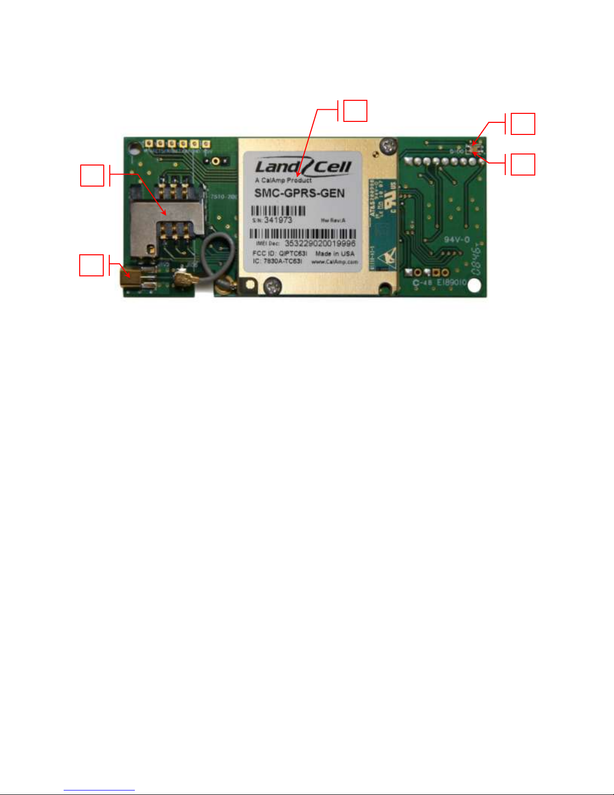
SMC Module Description
Top side reference
Fig. 2.1 SMC-GPRS Top Side
SMC-GPRS top side components:
1. Power: Green LED indicating cell module power on.
2. DCD: Red LED indicating Data Carrier Detect from cellular network.
3. RF (antenna): MMCX socket, primary antenna connection.
4. SIM: SIM Card Slot (SIM card purchased separately).
5. GSM Cell Module
Page 9 of 73
001-0004-829 Rev01
2
1
3
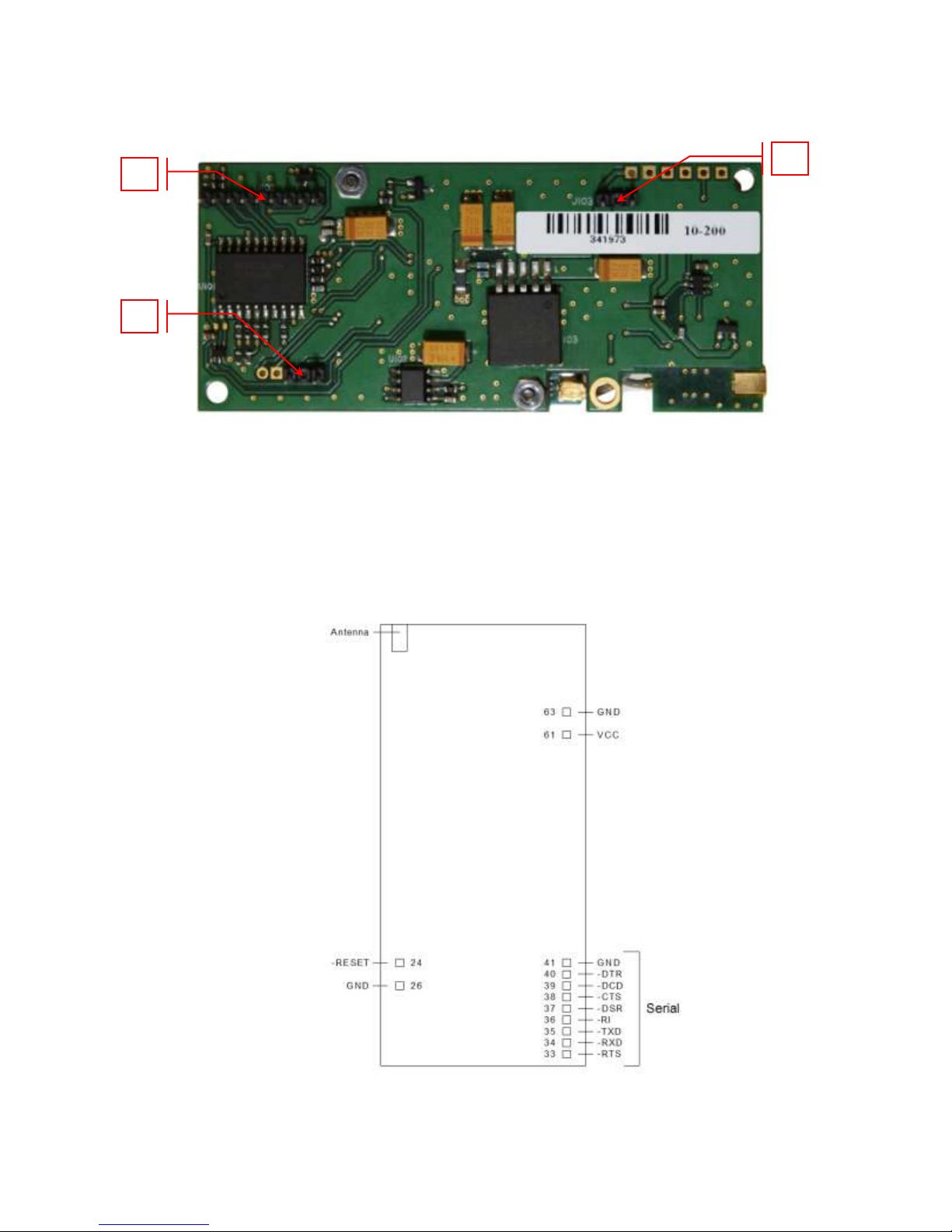
Bottom side reference
SMC-GPRS bottom side socket pins:
1. VCC/GND pins
2. –Reset/GND pins
3. SERIAL pins
Fig. 2.2 SMC-GPRS Bottom Side
Figure 2.3 SMC Pins, Top View
001-0004-829 Rev01
Page 10 of 73

Pin #
Pin
Name
I/O
Type
Description
24
-RESET
Input
This signal is used to force a reset procedure by providing a low
level for at least 10 ms. Data stored in volatile memory will be lost.
This line must be driven by an open drain or open collector. If
unused, keep line open.
26, 41, 63
GND
Ground
33
-RTS
Input
Request to Send. Signal used for hardware flow control
34
-RXD
Output
Received Data. Line used to send received data and modem
responses to the DTE (Data Terminal Equipment)
35
-TXD
Input
Transmitted Data. Line used to send data and transmit commands
from the DTE.
36
-RI
Output
Ring Indicator. Output low (ON) indicates the presence of a ring
signal.
37
-DSR
Output
Data Set Ready. Line used to indicate modem status to the DTE.
38
-CTS
Output
Clear to Send. Line controlled by the modem to indicate whether or
not the modem is ready to transmit data.
39
-DCD
Output
Data Carrier Detect. Line asserted by the DTE to indicate connection
status.
40
-DTR
Input
Data Terminal Ready. Line asserted by the DTE to indicate that it is
ready to transmit or receive data.
61
VCC
Power
+5 VDC ±0.25 VDC
Pin Descriptions
Digital Input lines: Input High, Min 3.675 V
Input Low, Max 1.4 V
Digital Output Lines: Output High, Min 4.0 V
Output Low, Max 0.4 V
Digital Line Current Drive: 2.0 mA
-RESET Input line: Input Low, Max 0.4 V, internal 22K ohm pull-up to 3.9VDC.
NOTE: VCC is the maximum voltage rating on Serial UART input pins.
Page 11 of 73
001-0004-829 Rev01
1 5 4 6 7 8 2 3 9
-
SSEECCTTIIOONN 44 -
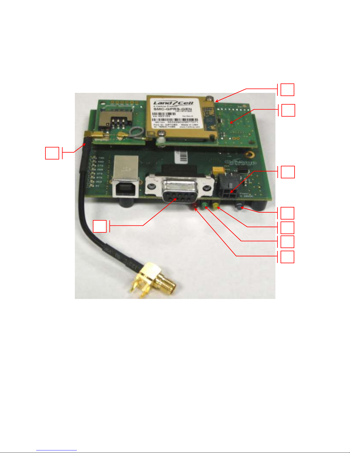
Development/Test board
The Development/Test board is required to interface the SCM-GPRS modem to a standard RS232
serial connection. The SMC test board also supplies the SMC-GPRS modem with the required +5VDC
supply voltage from an externally supplied 10 to 28 VDC power source, +12VDC typical.
DDEEVVEELLOOPPMMEENNTT//TTEESSTT BBOOAARRDD IINNTTEERRFFAACCEE
SMC-GPRS test board components:
1. SMC-GPRS modem
2. MMCX to SMA RF cable: Provides connection to external antenna.
3. RS-232 Port: Standard D-Sub, 9 pin, female connector.
4. Power Connector: Molex 4-pos 3MM receptacle (lower left: GND, lower right: +VDC).
5. Blue LED: Power Indicator
6. Yellow LED: DCD Indicator
7. Green LED: RXD Indicator
8. Red LED: TXD Indicator
9. RESET Switch: Bottom side of DK test board (under far right mounting screw)
Note: USB connector reserved for future use.
Figure 4.1 SMC modem with DK test board
001-0004-829 Rev01
Page 12 of 73
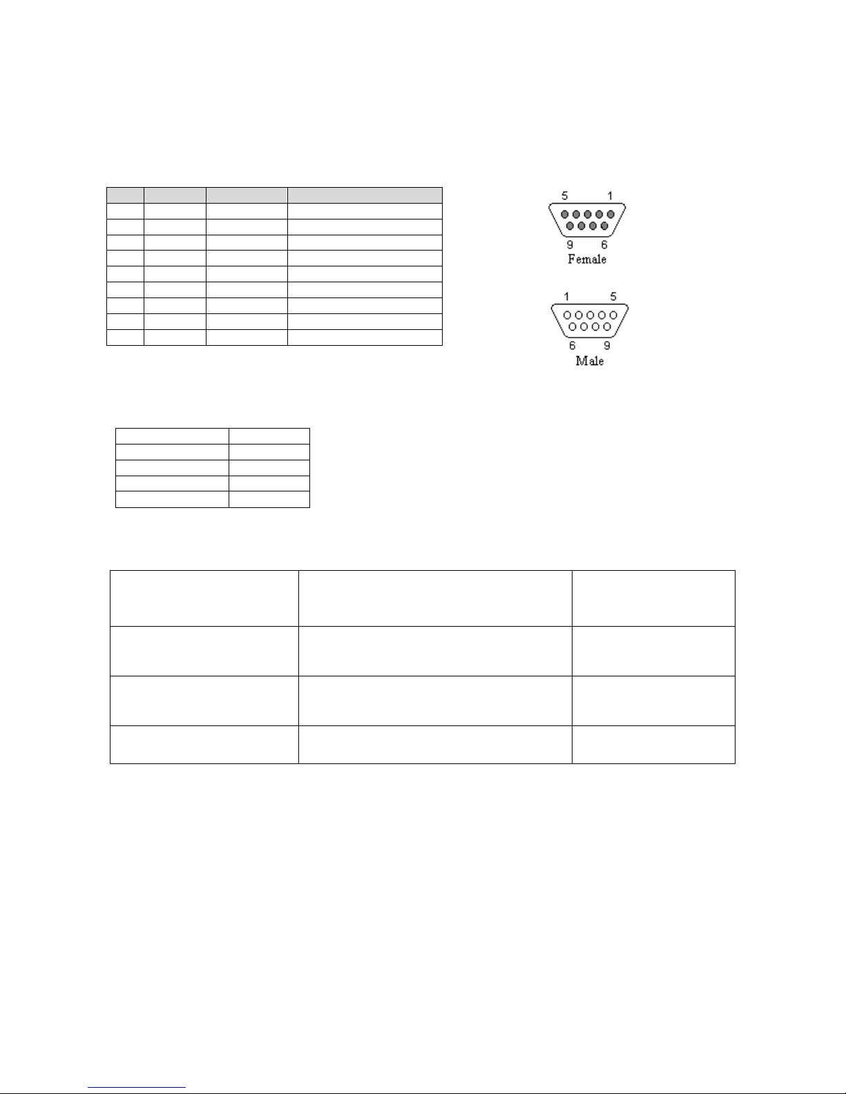
Pin
Name
Direction
Description
1
CD
«—
Carrier Detect
2
RX
«—
Receive Data
3
TX
—»
Transmit Data
4
DTR
—»
Data Terminal Ready
5
GND
System Ground
6
DSR
«—
Data Set Ready
7
RTS
—»
Request to Send
8
CTS
«—
Clear to Send
9
RI
«—
Ring Indicator
Bits Per Second
115,200
Data Bits
8
Parity
None
Stop Bits
1
Flow Control
Hardware
Antenna
3‖ Mag Mount Antenna
L2-ANT0003
Antenna Adapter Cable
MMCX to SMA cable
497-7500-003 or
697-7500-003
Power Supply
110 VAC input
DC Power Cable
150-7001-001
150-7500-002
Interface Cable
Serial Cable
L2-CAB0002
RS-232 Serial Port Integration Parameters
Table 4.2 provides the serial cable design information for the SMC-GPRS using the DK test
board.
Table 4.2 Standard RS-232 DE-9 Pin out
Note: Direction is DTE relative DCE.
Table 4.3 Default RS-232 Communication Parameters
Accessories
Primary Antenna
The primary antenna connection on the SMC-GPRS is a MMCX connector. Mounting options and
cable lengths are user‘s choice and application specific.
Page 13 of 73
001-0004-829 Rev01
-
SSEECCTTIIOONN 55 -
This section describes the use of the SMC test board to set up the SMC modem for internet access
using HyperTerminal and a dial-up network connection (DUN). Please refer to Appendix B for
details on setting up a modem driver for a DUN connection.
GGEETTTTIINNGG SSTTAARRTTEEDD UUSSIINNGG TTHHEE SSMMCC TTEESSTT BBOOAARRDD
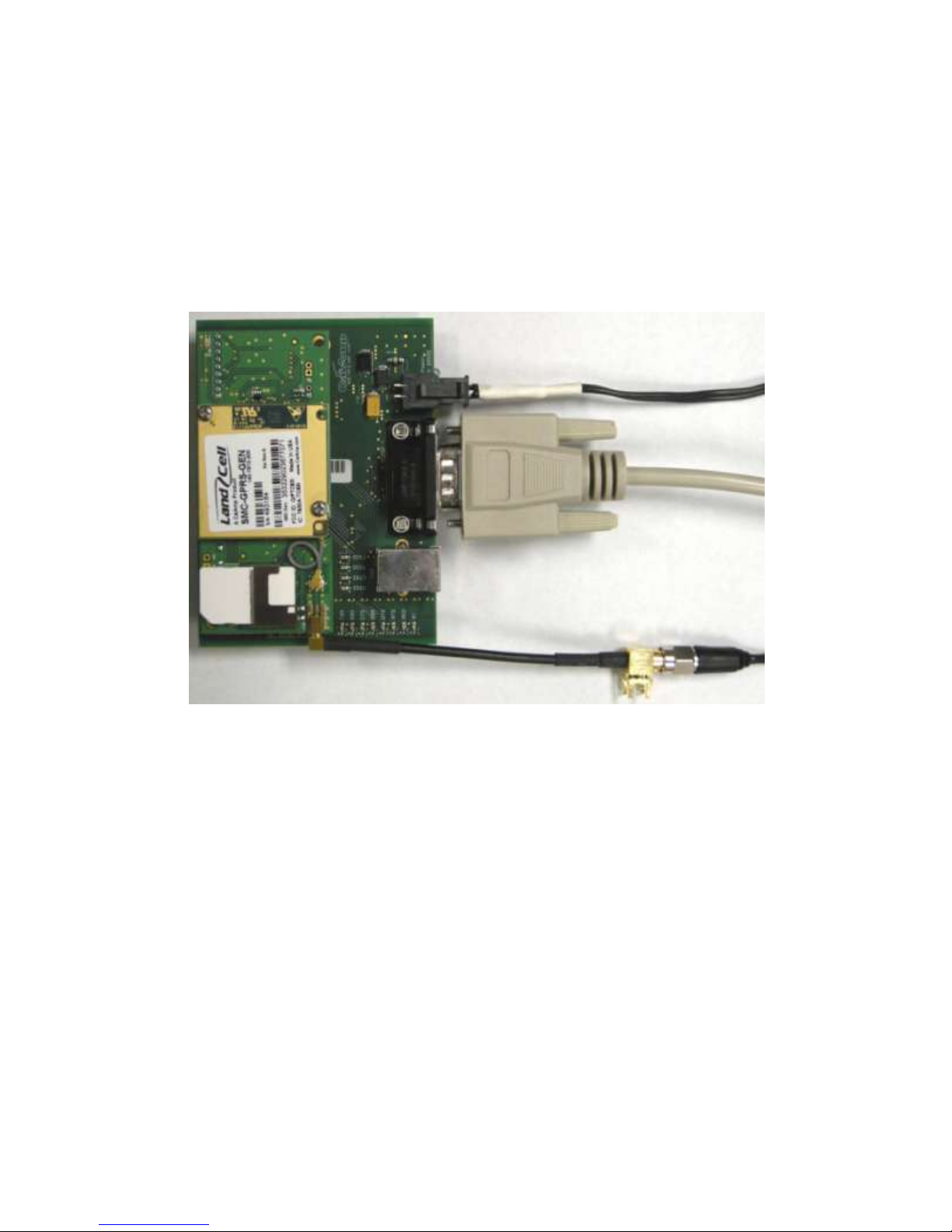
Connecting Up the SMC Test Board
Connect the Power cable, RS232 cable, Antenna cable to the SMC test board as shown in Figure 5.1.
Insert an active SIM card into the SMC modem.
Figure 5.1 SMC test board connections
HyperTerminal Settings
Open a HyperTerminal session and configure the properties for the COM port used to connect the
SMC test board.
Set HyperTerminal properties for:
Bits per second: 115200
Data bits: 8
Parity: None
Stop bits: 1
Flow control: Hardware
Page 14 of 73
001-0004-829 Rev01
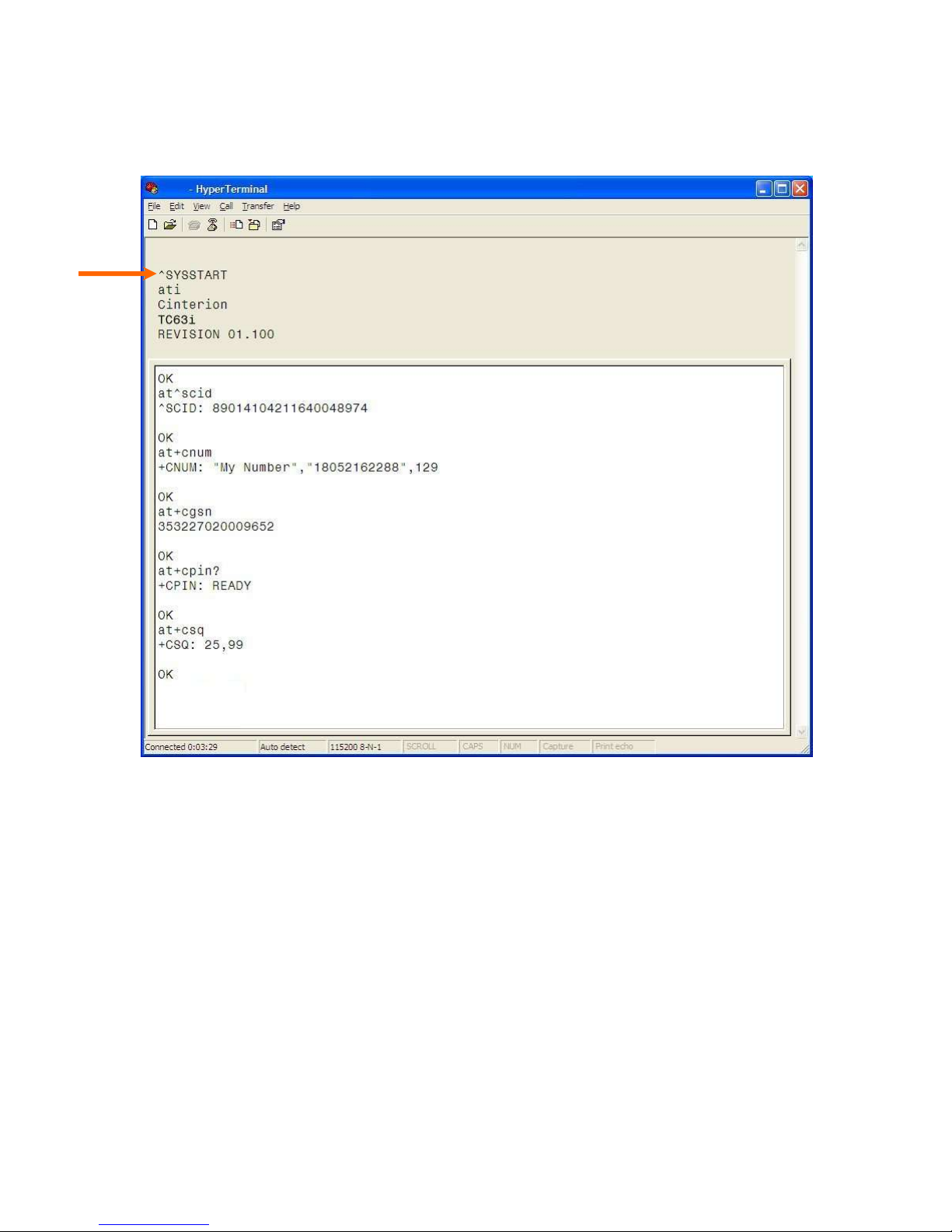
Verify SMC Modem Connectivity
Power on the SMC test board (+12VDC typical) and observe the HyperTerminal window for
^SYSSTART, indicating the SMC modem successfully powered on.
Figure 5.2 HyperTerminal screen responses
The ATI command prints the cell module product information. If you get an Error or no
communication, verify the modem is connected to the proper COM port and powered on. Refer to
Figure 5.2 for all the AT commands listed below.
Confirm your SIM card is properly installed with the AT^SCID command. A reply of ^SCID:<20
digit CID number> indicates the modem recognizes the SIM card and displays it‘s ID number.
Confirm the phone number currently in the modem with the AT+CNUM command. It should be 11
digits i.e. 18052162288. For some carriers the phone number may not display but will respond with
―OK‖. If the SIM card is not in the unit or not activated properly, the modem will reply with ―ERROR‖.
Verify the modems International Mobile Equipment Identity (IMEI) number with the AT+CGSN
command. The IMEI is used to identify GSM mobile equipment to the GSM network.
Page 15 of 73
001-0004-829 Rev01
Confirm that the SIM‘s PIN has been authenticated by the network using the AT+CPIN? command.
The reply should read ―+CPIN: READY‖. See Section 6 for SIM related information if ―READY‖ does
not display.
Verify good signal strength with the AT+CSQ command. A typical reply is +CSQ 25, 99. The first
number is signal strength and ranges from 0 to 31 (the higher the number, the stronger the signal).
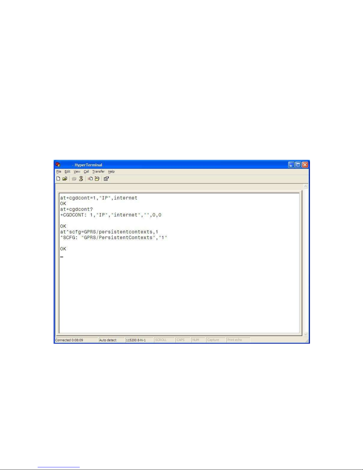
Define the Packet Data Protocol (PDP) Context
Next, the Access Point Name (APN) must be defined using the PDP Context command
AT+CGDCONT=1,“IP”,<apn> command. The <apn> is the access point name for a specific
cellular provider (for example AT+CGDCONT=1,‖IP‖,internet). The At+CGDCONT? command can be
issued to verify the PDP Context information.
The PDP context information can be set to non-volatile by issuing the
AT^SCFG=GPRS/Persistentcontexts=1 command. GPRS PDP context will not be reset by an
AT&F command. Refer to Figure 5.3.
Exit HyperTerminal before attempting to connect using a Dial-Up-Networking connection.
Figure 5.3 Set PDP Contexts, APN
001-0004-829 Rev01
Page 16 of 73
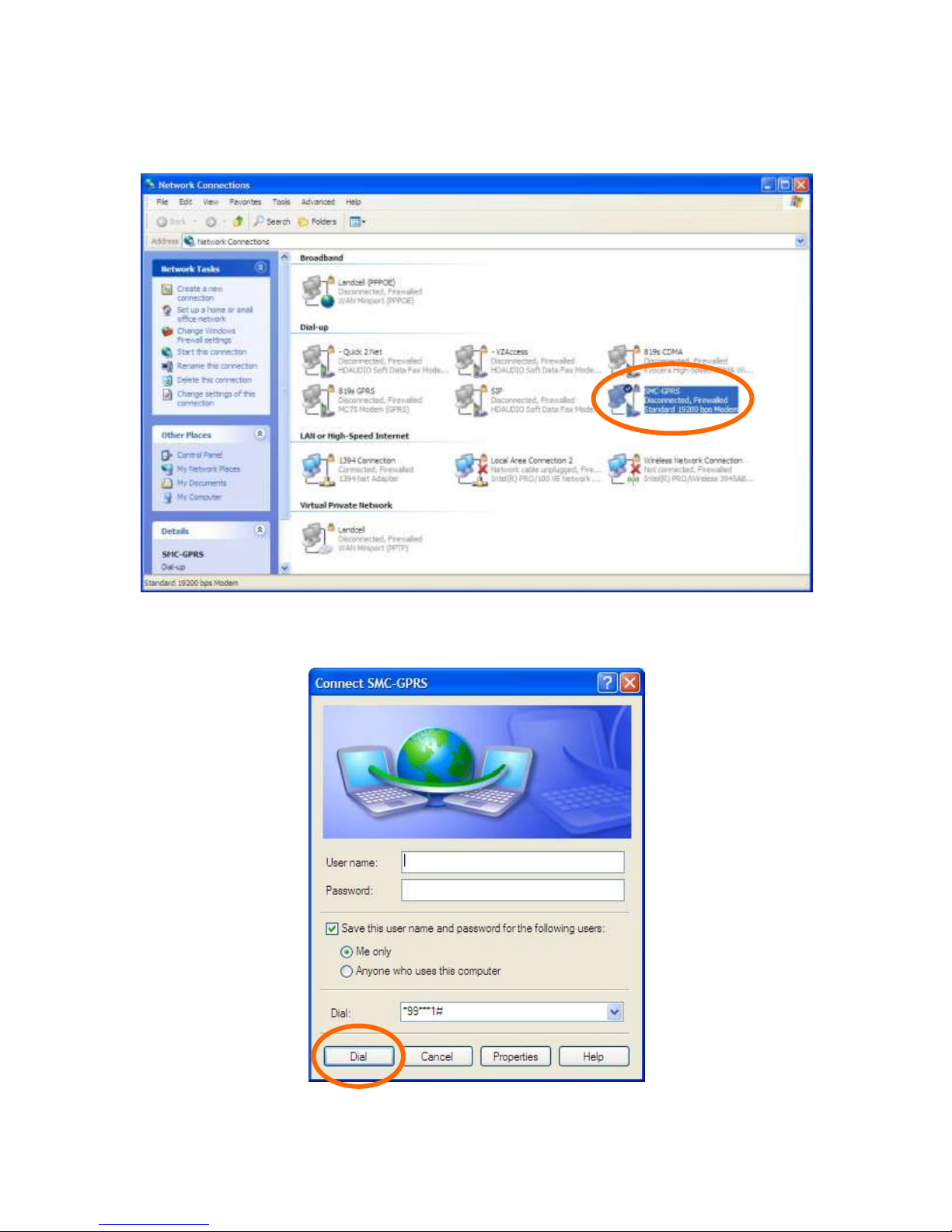
Connect using the Dial-Up-Network Connection
Go to the Network Connections screen and double click on the newly created Dial-Up connection (i.e.
SMC-GPRS).
When the connect window appears, set the username and password as defined for your carrier
(usually blank). Enter the phone number as *99***1# and click the Dial button.
001-0004-829 Rev01
Page 17 of 73
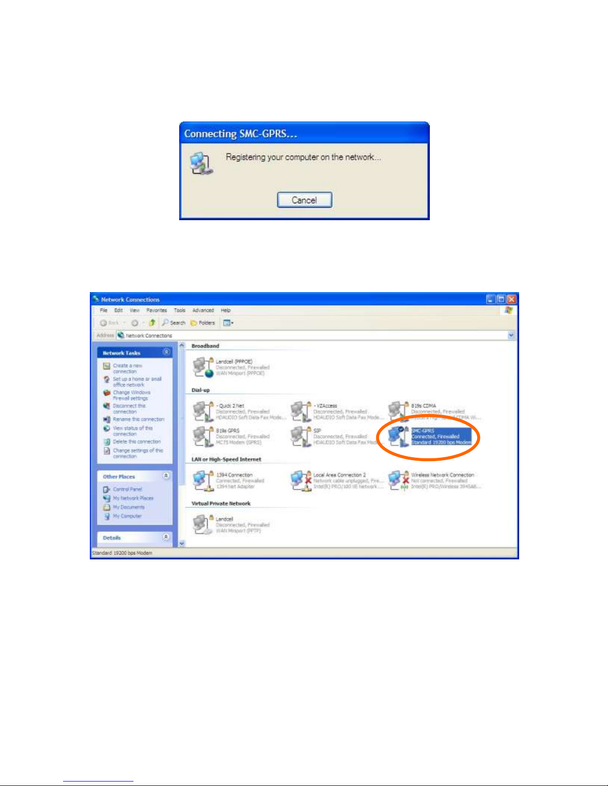
The modem will attempt to connect to the provider network. If the configured baud rate for the COM
port, the modem, and the DUN do not match, the DUN will not be able to talk to the modem
properly and you will get a hardware error message. Otherwise the DUN will contact the cellular
network and authenticate the user on the network.
Once connected you should be able to browse the internet thorough the DUN session. To confirm
this, disable any other network connections you may have running.
001-0004-829 Rev01
Page 18 of 73
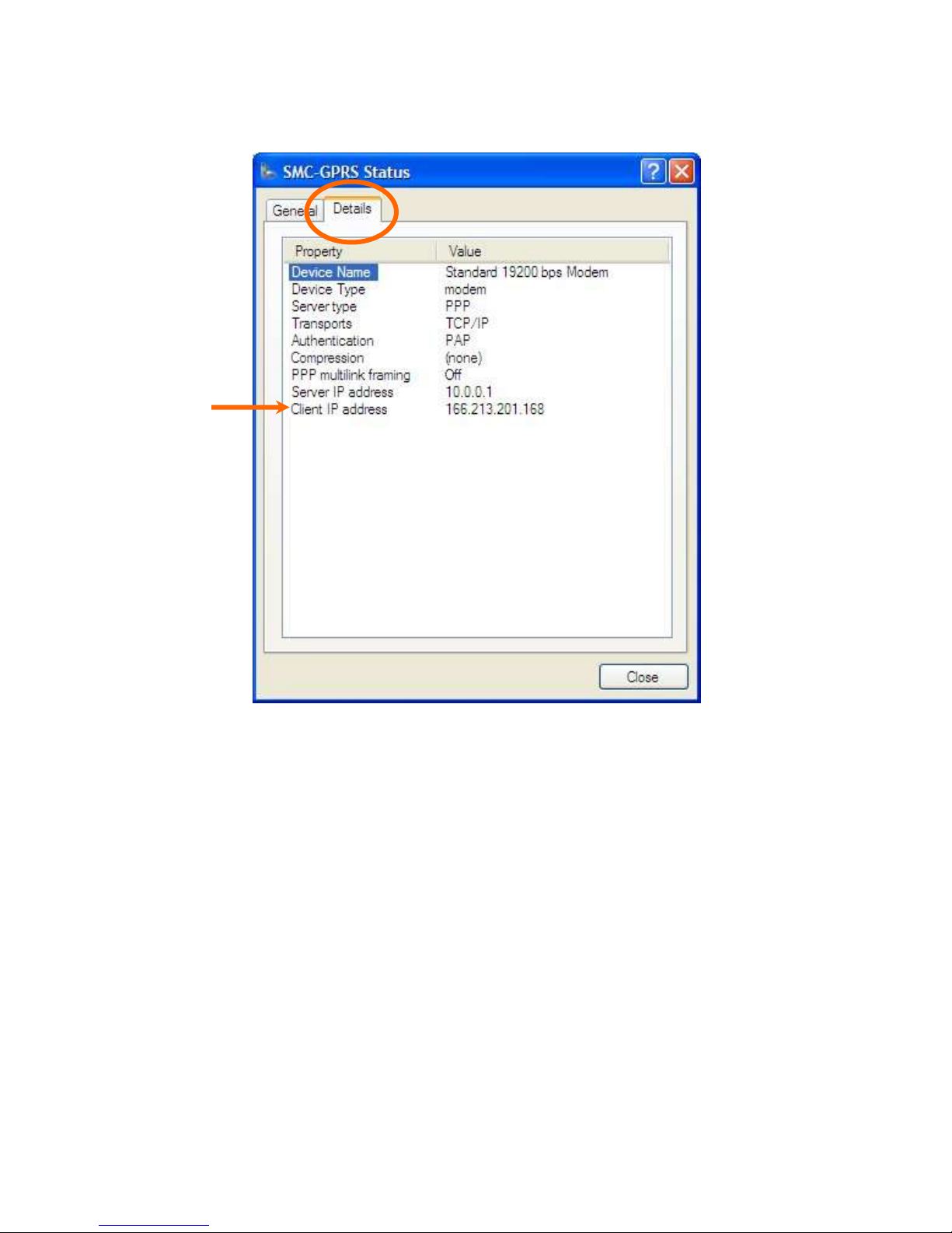
Right click on the connected Dial-Up connection icon in the task bar and select the Details tab. The
status of the connection will be displayed, including the IP address assigned by the carrier network.
Page 19 of 73
001-0004-829 Rev01

-
SSEECCTTIIOONN 66 -
The SIM card can be used to store a Personal Idetification Number (PIN) to authenticate users on
the network.
The AT+CPIN write command can be used to enter one of the passwords listed below. The read
command can be used to check whether or not the ME is waiting for a password, or which type of
password is required.
This may be for example the SIM PIN1 to register to the GSM network, or the SIM PUK1 to replace a
disabled SIM PIN1 with a new one, or the PH-SIM PIN if the client has taken precautions for
preventing damage in the event of loss or theft etc. If requested by the ME AT+CPIN may also be
used for the SIM PIN2 or SIM PUK2. If no PIN1 request is pending (for example if PIN1
authentication has been done and the same PIN1 is entered again) SMC modem responds "+CME
ERROR: operation not allowed"; no further action is required.
Each time a password is entered with AT+CPIN the module starts reading data from the SIM. The
duration of reading varies with the SIM card. This may cause a delay of several seconds before all
commands which need access to SIM data are effective.
AT+CPIN=<pin>[, <new pin>]
<pin>: Password (string type), usually SIM PIN1. If the requested password was a Pin Unlock Code
(PUK), such as SIM PUK1 or PH-FSIM PUK or another password, then <pin> must be followed by
<new pin>.
<new pin>: If the requested code was a PUK: specify a new password or restore the former disabled
password. See section ―What to do if PIN or password authentication fails?‖ for more information
about when you may need to enter the PUK.
Successful PIN authentication only confirms that the entered PIN was recognized and correct. The
output of the result code OK does not necessarily imply that the mobile is registered to the desired
network. Typical example: PIN was entered and accepted with OK, but the ME fails to register to the
network. This may be due to missing network coverage, denied network access with currently used
SIM card, no valid roaming agreement between home network and currently available operators etc.
The SMC modem offers various options to verify the present status of network registration: For
example, the AT+COPS command indicates the currently used network. With AT+CREG you can also
check the current status and activate an unsolicited result code which appears whenever the status
of the network registration changes (e.g. when the ME is powered up, or when the network cell
changes).
The <pin> and <new pin> can also be entered in quotation marks (e.g. "1234").
To check the number of remaining attempts to enter the passwords use the AT^SPIC command.
See AT+CPWD and AT^SPWD for information on passwords.
See AT+CLCK and AT^SLCK for information on lock types.
SSIIMM CCAARRDD SSPPEECCIIFFIICC IINNFFOORRMMAATTIIOONN
Page 20 of 73
001-0004-829 Rev01

Number of failed attempts
Time to wait before next input is allowed
1st failed attempt
No time to wait
2nd failed attempt
4 seconds
3rd failed attempt
3 * 256 seconds
4th failed attempt
4 * 256 seconds
5th failed attempt
5 * 256 seconds
6th failed attempt and so forth
6 * 256 seconds and so forth
What to do if PIN or password authentication fails?
PIN1 / PUK1:
After three failures to enter PIN 1, the SIM card is blocked (except for emergency calls). +CME
ERROR: 12 will prompt the client to unblock the SIM card by entering the associated PUK (= PIN
Unblocking Key / Personal Unblocking Key). After ten failed attempts to enter the PUK, the SIM card
will be invalidated and no longer operable (the device will respond with: +CME ERROR: 770, which
stands for: SIM invalid - network reject). In such a case, the card needs to be replaced. PIN1
consists of 4 to 8 digits, PUK1 is an 8-digit code only. To unblock a disabled PIN1 you have two
options:
• You can enter AT+CPIN=PUK1,new PIN1.
• You can use the ATD command followed by the GSM code **05*PUK*newPIN*newPIN#;.
PIN2 / PUK2:
PIN2 prevents unauthorized access to the features listed in AT+CPIN2. The handling of PIN2 varies
with the provider. PIN2 may either be a specific code supplied along with an associated PUK2, or a
default code such as 0000. In either case, the client is advised to replace it with an individual code.
Incorrect input of PUK2 will permanently block the additional features subject to PIN2
authentification, but usually has no effect on PIN1. PIN2 consists of 4 digits, PUK2 is an 8-digit code
only. To unblock a disabled PIN2 you have two options:
• You can enter AT+CPIN2=PUK2,new PIN2.
• You can use the ATD command followed by the GSM code **052*PUK2*newPIN2*newPIN2#;.
Phone lock:
If the mobile was locked to a specific SIM card (= "PS" lock or phone lock), the PUK that came with
the SIM card cannot be used to remove the lock. After three failed attempts to enter the correct
password, ME returns +CPIN: PH-SIM PUK (= response to read command AT+CPIN?), i.e. it is now
waiting for the Master Phone Code. This is an 8-digit device code associated to the IMEI number of
the mobile which can only by obtained from the manufacturer or provider. When needed, contact
Cinterion Wireless Modules GmbH and request the Master Phone Code of the specific module. There
are two ways to enter the Master Phone code:
• You can enter AT+CPIN=Master Phone Code
• You can use the ATD command followed by the GSM code *#0003*Master Phone Code#;.
Usually, the Master Phone Code will be supplied by mail or e-mail. If the received number is
enclosed in the *# codes typically used for the ATD option, it is important to crop the preceding
*#0003* characters and the appended #. Example: You may be given the string
*#0003*12345678#. When prompted for the PH-SIM PUK simply enter 12345678. If incorrectly
input, the Master Phone Code is governed by a specific timing algorithm: (n-1)*256 seconds (see
table below). The timing should be considered by system integrators when designing an individual
MMI.
Page 21 of 73
001-0004-829 Rev01

SIM locks:
These are factory set locks, such as "PF", "PN", "PU", "PP", "PC". An 8-digit unlocking code is
required to operate the mobile with a different SIM card, or to lift the lock. The code can only be
obtained from the provider. Failure to enter the password is subject to the same timing algorithm as
the Master Phone Code (see Table above).
Call barring:
Supported modes are "AO", "OI", "OX", "AI", "IR", "AB", "AG", "AC". If the call barring password is
entered incorrectly three times, the client will need to contact the service provider to obtain a new
one.
Page 22 of 73
001-0004-829 Rev01
 Loading...